Advertisement
Quick Links
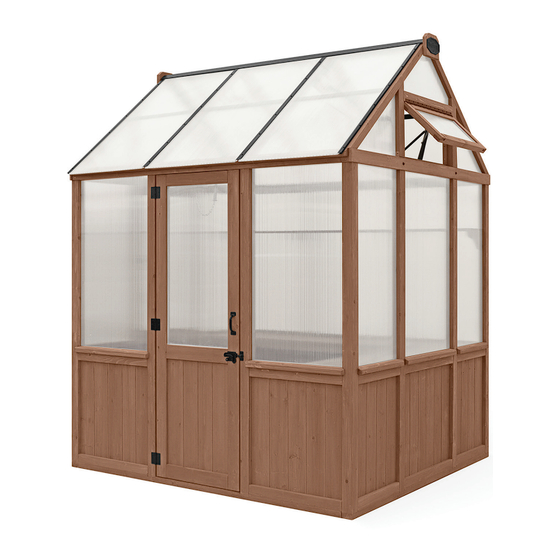
2.06 m (6.7 ft) x 2.32 m (7.6 ft)
Installation and Operating Instructions – YM12863
IMPORTANT, RETAIN FOR FUTURE REFERENCE: READ CAREFULLY
Yardistry – North America
Toll Free Customer Support:
1.888.509.4382
Mon - Fri, 8:30 am - 5:00 pm EST
(excl. holidays)
English and French Spoken
For extended hours see our website:
www.yardistrystructures.com
info@yardistrystructures.com
Patents Pending
Y40000-2863
GREENHOUSE
THIS ITEM IS INTENDED FOR OUTDOOR DOMESTIC USE ONLY.
NOT FOR COMMERCIAL USE.
11-11-2024
2.44 m
2.06 m
8 ft
(6.7 ft)
ITM. / ART. 1807163
HEIGHT:
2.9 m / 9.51 ft
2.32 m
2.96 m
(7.6 ft)
9.7 ft
TOP VIEW
Advertisement

Related Manuals for Yardistry YM12863

Summary of Contents for Yardistry YM12863
- Page 1 2.06 m (6.7 ft) x 2.32 m (7.6 ft) GREENHOUSE Installation and Operating Instructions – YM12863 ITM. / ART. 1807163 HEIGHT: 2.9 m / 9.51 ft IMPORTANT, RETAIN FOR FUTURE REFERENCE: READ CAREFULLY THIS ITEM IS INTENDED FOR OUTDOOR DOMESTIC USE ONLY.
- Page 2 Wood is NOT flame retardant and will burn. Grills, fire pits and chimineas are a fire hazard if placed too close to a Yardistry structure. Consult user’s manual of the grill, fire pit or chiminea for safe distances from combustible materials.
- Page 3 Limited Warranty Yardistry warrants that this product is free from defect in materials and workmanship for a period of one (1) year from the original date of purchase. In addition, for any product with lumber, all lumber is warranted for five (5) years against rot and decay. Polycarbonate panels are warranted for five (5) years against defect in materials and workmanship.
- Page 4 Instructions for Proper Maintenance Your Yardistry structure is designed and constructed of quality materials. As with all outdoor products it will weather and wear. To maximize the enjoyment, safety and life of your structure it is important that you, the owner, properly maintain it.
- Page 5 Assembly Tips Following are some helpful tips to make the assembly process smooth and efficient. PRE-ASSEMBLY: • Work on a raised, solid and flat surface such as a table or saw horse. • Keep all connections flush where shown in the instructions. •...
- Page 6 Sealant Application Tips, Warning and First Aid Information SEALANT: • All surfaces to be clean, dry, dust and grease free before application with temperatures above 5 ° C (41 ° F), no warmer than 35 ° C (95 ° F). •...
- Page 7 Structure Location Preparation Note: It is critically important you start with square, solid and level base to attach your Greenhouse. The hardware to mount the structure permanently will need to be purchased separately at your local hardware store. Before preparing your surface for the structure please double check for possibility of any underground utilities such as gas, telephone, cable or sprinkler lines.
- Page 8 Part Identification ( Dimensions are approximate and are shown to assist in the identification of parts for assembly. Actual dimensions may be smaller or larger. 1pc. (1129) Top Door Block FSC 690 mm (27-3/16") Y50229-1129 2pc. (1130) Door Block FSC 1935.2 mm (76-3/16") Y50229-1130 2pc.
- Page 9 Part Identification ( Dimensions are approximate and are shown to assist in the identification of parts for assembly. Actual dimensions may be smaller or larger. 1pc. (2239) Front Shelf FSC 1814.7 mm (71-7/16") Y50229-2239 2pc. (2240) Fascia FSC 2230 mm (87-13/16") Y50229-2240 1pc.
- Page 10 Part Identification ( Dimensions are approximate and are shown to assist in the identification of parts for assembly. Actual dimensions may be smaller or larger. 2pc. (2254) Window Top Trim FSC 688.9 mm (27-1/8") 1pc. (2293) Shelf Block FSC 829.6 mm (32-1/2") Y50229-2254 Y50229-2293 1pc.
- Page 11 Part Identification ( Dimensions are approximate and are shown to assist in the identification of parts for assembly. Actual dimensions may be smaller or larger. 2pc. (2268) Wall Panel FSC 762 mm (30") 1pc. (1175) Door Panel FSC 1943.1 mm (76-1/2") Y70229-1175 Y70229-2268 1pc.
- Page 12 Part Identification ( Dimensions are approximate and are shown to assist in the identification of parts for assembly. Actual dimensions may be smaller or larger. 33pc. Wood Screw #7 x 3/4" Y06018-003 95pc. Wood Screw #8 x 1-1/4" Y06091-511 49pc. Wood Screw #8 x 2" Y06091-520 32pc.
- Page 13 1pc. (4pk) PC Wall Panel Y70800-1058 1pc. Gazebo ID Plaque Y70800-104 1pc. PC Wall Center Short Y61800-774 1pc. Yardistry Name Plaque Y00418-749 1pc. (2pk) Roof PC Panel B 1pc. (4pk) Roof PC Panel A Y70800-1061 Y70800-1060 2pc. Silicone Clear (300 ml Tube) Y90100-002 1pc.
- Page 14 Part Identification ( Dimensions are approximate and are shown to assist in the identification of parts for assembly. Actual dimensions may be smaller or larger. 2pc. Door Handle Y00418-864 1pc. Aluminum Vent 2pc. Cathedral Gusset Y01018-1057 Y00418-1048 1pc. (4pk) Jamb Mount Y70818-1051 1pc.
- Page 15 Part Identification ( Dimensions are approximate and are shown to assist in the identification of parts for assembly. Actual dimensions may be smaller or larger. 1pc. (4pk) Short Wall PC U-Channel Y70800-1064 1pc. (4pk) Roof PC U-Channel Y70800-1062 1pc. (2pk) Wall PC U-Channel 1pc.
- Page 16 • Please retain this information for future reference. You will need this information if you contact the Consumer Relations Department. PRODUCT NUMBER: YM12863 CARTON I.D. STAMP: __ __ __ __ __ 14459 ___ (Box 1) CARTON I.D. STAMP: __ __ __ __ __ 14459 ___ (Box 2)
- Page 17 STOP STOP STOP STOP IMPORTANT! POLYCARBONATE INFORMATION • Each polycarbonate panel has a UV coating on only ONE (1) side of the panel. STOP PAGE/IMPORTANT – Polycarbonate • To install properly so the UV coating is on the outside of the panel, the notch in the panel needs to be oriented to the bottom right-hand side of the assembly when on •...
- Page 18 • To install properly so the UV coating is on the outside of the panel, orientated to the bottom right-hand corner of the assembly STOP STOP STOP STOP IMPORTANT! TAPE INFORMATION • Photo of PC Sheet and a make note of the small notch on bottom ri •...
- Page 19 IMPORTANT: Door may be installed on Side Wall OR End Wall. Door and Access Window will switch locations. Door cannot be installed on Gable Vent end. Choose door location before beginning your assembly. For the purposes of this instruction the door will be installed on the Side Wall.
- Page 20 Step 2: End Wall with Gable Vent Assembly Part 1 Note cutout orientation Corner Posts F2.1 Note cutout orientation (2237) orner Posts Holes towards top F2.3 Outside View (2237) F2.2 (2244) Grooves face inwards Notch (2237) Grooves face to the back Flush (2244) Flush...
- Page 21 Step 2: End Wall with Gable Vent Assembly Part 2 F2.4 Outside View (2249) Center Posts F2.5 Center Posts Note cutout orientation (2249) (2237) (2237) (2249) (2244) (1147) F2.6 (Screws installed in next step) Flush (1147) (2244) Wood Parts Hardware 2 x (2249) Center Post #10 x 4”...
- Page 22 Step 2: End Wall with Gable Vent Assembly Part 3 F2.7 Outside View F2.8 d Panels 2 (2237) (2249) End Panels 2 (1552) FB Panel (1147) (1147) F2.9 (1147) (2244) Hardware #8 x 3” Wood Screw #10 x 4” Wood Screw support@yardistrystructures.com...
- Page 23 Step 2: End Wall with Gable Vent Assembly Part 4 F2.10 Outside View F2.11 (2249) (2268) (2268) (2244) F2.12 (2244) F2.13 (2268) Tight Center Wall Panel (2268) Corner Bracket (yellow) Center Wall Panel Wood Parts Components Hardware 1 x (2268) Wall Panel 2 x Corner Bracket #8 x 3”...
- Page 24 Step 2: End Wall with Gable Vent Assembly Part 5 Guide Spacer to sit in grooves of Sills and Posts for proper alignment, then to be removed. F2.14 Outside View F2.15 (1188) Guide Spacer Sills Sills Sills (2233) F2.11 (2235) (2233) (2233) (2235)
- Page 25 Step 2: End Wall with Gable Vent Assembly Part 6 F2.18 (2243) Outside View (2243) F2.19 End wall top ra End wall top rail End wall top rail (2243) F2.20 F2.21 Tight (2243) Flush (2237) (2249) Hardware Wood Parts 1/4” Flat Washer #8 x 2”...
- Page 26 Step 2: End Wall with Gable Vent Assembly Part 7 Remove film from both sides of PC Gable Panel Left, PC Gable Panel Right and PC Wall Center Short Top Tape F2.22 Note: UV Outside View F2.23 Coating to the outside of the Outside View frame...
- Page 27 Step 2: End Wall with Gable Vent Assembly Part 8 Pre-drill all pilot holes before installing Pan Screws. F2.25 F2.27 (2246) (2246) (2236) (2236) Inside View Outside View Corner Bracket Corner Jamb Bracket Mount Note: Attach Jamb Mounts to 2249’s before attaching to 2236 and 2246 F2.28...
- Page 28 Step 2: End Wall with Gable Vent Assembly Part 9 F2.30 Align groove (2263) F2.29 Outside View (2263) Guide Guide Spacer Spacer Vent Top Wood Parts Hardware Vent Top 1 x (2263) Gable End Vent - Top #10 x 4” Wood Screw support@yardistrystructures.com...
- Page 29 Step 2: End Wall with Gable Vent Assembly Part 10 Remove film from both sides of Gable Center. Top Tape Refer to pages 17 and 18 and apply top and bottom tape to Gable Center. F2.32 Gable Poly F2.31 Gable Center Outside View Bottom Tape Note: Notches...
- Page 30 Step 2: End Wall with Gable Vent Assembly Part 11 F2.34 Outside View (2248) (2247) Rafters Flush (2247) F2.35 (2248) Flush and Tight Flush Wood Parts Hardware 1 x (2248) Rafter Left #10 x 4” Wood Screw 1 x (2247) Rafter Right #10 x 3”...
- Page 31 Step 2: End Wall with Gable Vent Assembly Part 12 F2.36 Outside View (2265) F2.37 Outside View F2.38 Flush (2265) Inside View (2247) (2248) Peak Spacer Wood Parts Hardware #8 x 2” Wood Screw 1 x (2265) Peak Spacer support@yardistrystructures.com...
- Page 32 Step 3: End Wall Assembly Part 1 Note cutout orientation Corner Posts F3.1 Note cutout orientation (2237) orner Posts Holes towards top F3.3 Outside View (2237) F3.2 (2244) Grooves face inwards Notch (2237) Grooves face to the back Flush (2244) Flush Wood Parts Hardware...
- Page 33 Step 3: End Wall Assembly Part 2 F3.4 Outside View Center Posts (2249) F3.5 Center Posts Note cutout orientation (2249) (2237) (2237) (2249) (2244) (1147) F3.6 Note: Screws installed in next step Flush (1147) Tight (2244) Wood Parts Hardware 2 x (2249) Center Post #10 x 4”...
- Page 34 Step 3: End Wall Assembly Part 3 F3.7 Outside View F3.8 d Panels 2 (2237) (2249) End Panels 2 (1552) FB Panel (1147) (1147) F3.9 (1147) (2244) Hardware #8 x 3” Wood Screw #10 x 4” Wood Screw support@yardistrystructures.com...
- Page 35 Step 3: End Wall Assembly Part 4 Note: If Door Panel is being installed on the End Wall disregard this step. F3.10 Outside View F3.11 (2249) (2268) (2268) (2244) F3.12 (2244) F3.13 (2268) Tight (2268) Center Wall Panel Corner Bracket (yellow) Center Wall Panel Wood Parts...
- Page 36 Step 3: End Wall Assembly Part 5 Guide Spacer to sit in grooves of Sills and Posts for proper alignment, then to be removed. F3.14 (2237) Outside View F3.15 (2249) F3.6 (1188) Guide Spacer (2233) (2253) (2233) (1147) (2268) (2244) F3.16 F3.17 Guide Spacer...
- Page 37 Step 3: End Wall Assembly Part 6 F3.18 (2243) Outside View F3.19 (2243) End wall top rail F3.21 (2243) F3.20 Flush (2243) Flush (2237) (2249) Hardware Wood Parts 1/4” Flat Washer #8 x 2” Wood Screw 1 x (2243) End Wall - Top Rail 1/4 x 3”...
- Page 38 Step 3: End Wall Assembly Part 7 Remove film from both sides of PC Gable Panel Left and PC Gable Panel Right. Top Tape F3.22 F3.23 Outside View Note: UV PC Gable Panel Coating to the PC Gable Panel Right outside of the Left frame...
- Page 39 Step 3: End Wall Assembly Part 8 F3.25 F3.27 Inside View Outside View (2261) (2262) (2262) (2261) Corner Bracket Corner Bracket Jamb (2243) Mount Note: Attach Jamb Mounts to 2249’s before attaching to F3.28 F3.26 2261 and 2262 Outside View Inside View (2261) (2262)
- Page 40 Step 3: End Wall Assembly Part 9 F3.29 F3.30 Inside View Outside View (2254) (2243) F3.16 F3.32 F3.31 Outside View (2254) Inside View (2243) (2243) Flush (2254) Wood Parts Hardware 1 x (2254) Window Top Trim #8 x 2-1/2” Wood Screw support@yardistrystructures.com...
- Page 41 Step 3: End Wall Assembly Part 10 Remove film from both sides of Gable Center Tall. Refer to pages 17 and 18 and apply top and bottom tape to Gable Center Tall. F3.34 Note: UV Outside View Coating to the outside of the Gable Center Top Tape...
- Page 42 Step 3: End Wall Assembly Part 11 F3.36 Outside View (2248) (2247) Flush (2247) F3.37 (2248) Flush and Tight Flush Wood Parts Hardware 1 x (2248) Rafter Left #10 x 4” Wood Screw 1 x (2247) Rafter Right #10 x 3” Wood Screw support@yardistrystructures.com...
- Page 43 Step 3: End Wall Assembly Part 12 F3.38 F3.39 Outside View Outside View (2265) F3.22 F3.40 Inside View Flush (2247) (2248) (1539) Left Roof Rafter Wood Parts Hardware #8 x 2” Wood Screw 1 x (2265) Peak Spacer support@yardistrystructures.com...
- Page 44 Step 4: Side Wall with Vent Assembly Part 1 Note cutout facing up F4.1 (2249) F4.2 Outside View Holes (2249) towards top (2250) F4.3 (2249) Flush (2250) Holes towards top (2250) Wood Parts Hardware 2 x (2249) Center Post #10 x 4” Wood Screw 1 x (2250) Side Wall - Base support@yardistrystructures.com...
- Page 45 Step 4: Side Wall with Vent Assembly Part 2 F4.4 Outside View (2249) F3.28 Inside View F4.5 (1552) (2250) (1552) F4.6 F4.7 (1552) (1136) Inside Vent Trim Wood Parts Hardware #8 x 3” Wood Screw 2 x (1552) FB Panel #10 x 4”...
- Page 46 Step 4: Side Wall with Vent Assembly Part 3 F4.8 Outside View (2249) F4.9 Corner (2275) Bracket (2275) F4.11 F4.10 (2275) (2275) Corner Bracket (yellow) Components Wood Parts Hardware 1 x (2275) Vent Wall Panel 2 x Corner Bracket #8 x 3” Wood Screw #10 x 1-1/4”...
- Page 47 Step 4: Side Wall with Vent Assembly Part 4 Guide Spacer to sit in grooves of Sills and Posts for proper alignment, then to be removed. F4.12 F4.13 Outside View Wall (1188) Panel Guide Spacer Sill 2.54 cm F4.14 [1 in] F4.15 (2234) (2235)
- Page 48 Step 5: Side Wall with Door Assembly Part 1 F5.1 Holes towards top F5.2 Outside View (2242) (2241) F4.8 (2250) (1152) Side Wall Panel (2250) Note: Cutout faces (2241) F5.3 (2242) (2250) Wood Parts Hardware 1 x (2241) Door Post Left #10 x 4”...
- Page 49 Step 5: Side Wall with Door Assembly Part 2 F5.4 Outside View (2241) (2242) F5.5 (1552) (1552) (1552) (2250) (1552) (2241) F5.6 F5.7 (1552) (2250) Wood Parts Hardware #8 x 3” Wood Screw 2 x (1552) FB Panel #10 x 4” Wood Screw support@yardistrystructures.com...
- Page 50 Step 5: Side Wall with Door Assembly Part 3 Note: If Door is being installed on the End Wall, refer to page 35 - Step 3 Part 4 to install (2268) here. Guide Spacer to sit in grooves of Sills and Posts for proper alignment, then to be removed. F5.8 Outside View F5.9...
- Page 51 Step 6: Frame Assembly Part 1 Remove film from both sides of PC Wall Panel. F6.2 F6.1 Outside View Note: UV Coating to the PC Wall Panel outside of the frame PC Wall Panel Note: Notches always at the bottom right of each panel from the outside Refer to pages 17 and 18 and apply...
- Page 52 Step 6: Frame Assembly Part 2 F6.6 Note: UV Remove film from both sides of PC Wall Panels. Coating to the Outside View outside of the Top Tape F6.5 frame PC Wall Panel PC Wall Panel Refer to pages 17 and 18 and apply top and bottom tape to PC Wall Panel.
- Page 53 Step 6: Frame Assembly Part 3 Remove film from both sides of PC Wall Panel. F6.11 PC Wall Panel Top Tape End Wall F6.10 Assembly Side Wall Assembly PC Wall Panel Refer to pages 17 and Notch 18 and apply top and bottom tape to PC Wall Panel.
- Page 54 Step 6: Frame Assembly Part 4 F6.16 F6.15 Inside View 40 Degree Roof to Post Bracket (2251) F6.17 Outside View 40 Degree Roof to Post Bracket F6.19 F6.18 (2251) (2251) (2251) Hardware Components Wood Parts 1/4” Flat Washer #8 x 2” Wood Screw 4 x 40 Degree Roof to Post Bracket 2 x (2251) Side Wall - Top 1/4 x 3”...
- Page 55 Step 6: Square Assembly Part 5 Check that assembly is square and that diagonal distance from inside Post to inside Post measures 2.79 m (9 ft 2-1/8 in). Side Wall F6.20 2.79 m 9'-2 8 " End Wall with End Wall [9 ft 2-1/8 in] 2.798m Vent...
- Page 56 Step 6: Secure Assembly to Base Part 6 Using the purchased hardware as mentioned on page 7, pre-drill then secure the Front Wall, Back Wall and Side Walls to the base in the locations shown F6.21 Side Wall End Wall with End Wall Vent Side Wall with...
- Page 57 Step 6: Frame Assembly Part 7 F6.22 #10 X 1-1/4” Pan Screws Connects Corner Bracket to bottom 4 corners. F6.23 Corner F6.24 Bracket Corner (2250) Bracket (2244) per bracket per bracket (yellow) (yellow) Components Hardware 12 x Corner Bracket 24 x #10 x 1-1/4”...
- Page 58 Step 6: Frame Assembly Part 8 F6.26 Remove film from both sides of PC Wall Center. PC Wall Center Notch Top Tape F9.1 F6.25 PC Wall Center Refer to pages 17 and 18 and apply top and bottom tape to PC Wall Center.
- Page 59 Step 6: Frame Assembly Part 9 Short Wall PC U-Channel PC Wall Center F6.28 Long Wall PC U-Channel PC Wall Panel PC Wall Panel F6.30 Short Wall PC Inside View U Channel/ Long Wall PC U EPDM Nylon Channel F6.29 Washer PC Wall Panel / PC Wall Center...
- Page 60 Step 6: Frame Assembly Part 10 F6.31 Outside View Flush F6.32 (2240) F6.33 Wood Parts Hardware 10 x #8 x 2” Wood Screw 2 x (2240) Fascia support@yardistrystructures.com...
- Page 61 Step 7: Roof Frame Assembly Build two Roof Frame Assemblies F7.1 (2245) (2252) F7.2 Flush (2245) (2252) x 4 per frame Wood Parts Hardware #8 x 3” Wood Screw 4 x (2245) Rafter 2 x (2252) Ridge support@yardistrystructures.com...
- Page 62 Step 8: Attach Roof Frame Assemblies Part 1 F8.1 Roof Frame Assembly (2265) F8.3 F8.2 (2245) (2251) Tight Flush (2240) (2252) Flush Hardware #10 x 4” Wood Screw support@yardistrystructures.com...
- Page 63 Step 8: Attach Roof Frame Assemblies Part 2 F8.4 F8.6 F8.5 (2245) Flush and tight Tight (2265) (2251) Flush (2252) (2240) Hardware #10 x 4” Wood Screw #8 x 2” Wood Screw support@yardistrystructures.com...
- Page 64 Step 8: Attach Roof Frame Assemblies Part 3 F8.7 F8.8 x 20 (black) Hardware 20 x #10 x 1-1/4” Black Pan Screw support@yardistrystructures.com...
- Page 65 Step 9: Roof Peak Assembly F9.2 x 14 PC Ridge Tight PC Ridge F9.1 F9.4 Apply sealant where PC Ridge Caps meet and on each end Note: All surfaces to be clean, dry, dust and grease free before application with temperatures above 5 °...
- Page 66 Step 10: Roof Assembly Part 1 H Channel Centered on Rafter F10.1 F10.2 PC Ridge Tight H Channel F10.3 H Channel x 12 (black) Components Hardware 4 x H Channel 24 x #10 x 1-1/4” Pan Screw (black) support@yardistrystructures.com...
- Page 67 Step 10: Roof Assembly Part 2 Remove film from both sides of Roof PC Panel B. F10.4 Refer to pages 17 and 18 and H Channel apply top and bottom tape to PC Roof Panel B. Roof PC Panel B Top Tape F10.5 Flush...
- Page 68 Step 10: Roof Assembly Part 3 Remove film from both sides of Roof PC Panel A. F10.8 Roof PC F10.7 Panel A E Channel Top Tape E Channel Note: Notches always at the bottom right of each panel from the outside Bottom Tape Slide Roof PC Panel A into H...
- Page 69 Step 10: Roof Assembly Part 4 F10.11 (black) E Channel F10.12 PC Ridge Cap Flush Roof PC Panel A Note: Roof PC Panel A slides into PC Ridge Cap Hardware 24 x #10 x 1-1/4” Pan Screw (black) support@yardistrystructures.com...
- Page 70 Step 10: Roof Assembly Part 5 Repeat Step 10 for other side of roof. F10.13 Roof PC U Channel/ Long F10.14 Roof PC U Channel Roof PC Long Roof PC Roof PC U-Channel U-Channel U-Channel PC Wall Panel / PC Wall Center F10.15 EPDM Nylon Note: Apply bead...
- Page 71 Step 11: Attach Gussets F11.1 Cathedral Gusset F11.2 Roof Panels removed for clarity x 12 (black) Hardware Components 2 x Cathedral Gusset 12 x #10 x 1-1/4” Pan Screw (black) support@yardistrystructures.com...
- Page 72 Step 12: Install Supports F12.1 PC Support PC Support Brace A Brace B F12.2 Parts removed for clarity PC Support PC Support PC Support Brace A Brace B Brace B Note: This edge is tight to Roof PC Panel A and Roof PC Panel B x 24 F12.3...
- Page 73 Step 13: Gable Vent Assembly Part 1 F13.2 This notch up F13.3 Flush F13.1 (2254) F13.4 F13.5 Parts removed for clarity Wood Parts Hardware 1 x (2254) Window Top Trim #8 x 2-1/2” Wood Screw support@yardistrystructures.com...
- Page 74 Step 13: Gable Vent Assembly Part 2 F13.6 Outside View (2264) (2236) F13.7 (2246) (2264) F13.8 Inside View Flush (2264) (2236) Wood Parts Hardware 2 x (2264) Vent Trim Side #8 x 1-1/4” Wood Screw support@yardistrystructures.com...
- Page 75 Step 13: Gable Vent Assembly Part 3 F13.9 Outside View Continuous Hinge (short) x 12 F13.10 Side View x 12 Continuous Hinge (2282) (2282) Notch on inside bottom Wood Parts Hardware Components 1 x Continous Hinge (short) 12 x #8 x 1/2” Pan Screw 1 x (2282) Gable End Vent support@yardistrystructures.com...
- Page 76 Step 14: Attach Gable Vent F14.1 Outside View x 12 Center Gable End Vent in opening F14.2 (2264) Hardware 12 x #8 x 1/2” Pan Screw support@yardistrystructures.com...
- Page 77 STOP STOP STOP STOP IMPORTANT! DOUBLE SPRING TEMPERATURE CONTROL INFORMATION • The Double Spring Temperature Control is designed to automatically open and close with changes in temperature. It must not be opened or closed manually. Doing so will result in damage to the component. •...
- Page 78 Double Spring Temperature Control Part Breakdown Spring Assembly Top View Frame Window Arm T-Tube Window Cylinder Nut Bracket Spring Assembly Frame Arm Side View Window Arm Window Bracket Cylinder Piston Rod Cyliner Thread Bracket Cylinder Pin Assembly Pin Components 1 x Double Spring Temperature Control support@yardistrystructures.com...
- Page 79 Step 15: Attach Temperature Control Part 1 F15.1 F15.2 Bracket F15.3 Bracket S12 (yellow) 2.54 cm Centered [1 in] Hardware #10 x 1-1/4” Pan Screw (yellow) support@yardistrystructures.com...
- Page 80 Step 15: Attach Temperature Control Part 2 F15.4 Spring A: Remove Spring from each side of Double Double Spring Temperature Control Spring Temperature Control. (F15.4) B: Insert Assembly Pin into holes on Frame Arm. (F15.5) C: On a flat surface open Double Spring Spring Temperature Control as shown in F15.6.
- Page 81 Step 15: Attach Temperature Control Part 3 F: From the bottom of T-Tube and Piston Rod insert Cylinder Pin as shown in F15.9 and F15.10. G: Remove Assembly Pin from Frame Arm. Keep pin for future use. (F15.11) F15.10 T-Tube F15.9 Assembly Frame Arm...
- Page 82 Step 15: Attach Temperature Control Part 4 H: Re-attach Springs to T-Tube posts making sure they are seated in the grooves of the posts. (F15.12 and F15.13) I: Re-attach other end of Springs to Cylinder Nut posts making sure they are seated in the grooves of the posts. (F15.14 and F15.15) F15.13 Cylinder...
- Page 83 Step 15: Attach Temperature Control Part 5 Note: Outside temperature should be cool for this step. F15.16 F15.17 (yellow) Leave a space F15.18 Frame Press together Arm post bottom of Frame Arm Bracket holes Hardware #10 x 1-1/4” Pan Screw (yellow) support@yardistrystructures.com...
- Page 84 Step 15: Attach Temperature Control Part 6 NOTE: Do not install the mesh tight. The Mesh remains baggy to allow the temperature controller to move freely. F15.19 Inside View 2.54 cm [1 in] Mosquito Mesh Panel 3.81 cm 3.81 cm [1.5 in] [1.5 in] Flush...
- Page 85 Step 16: Access Window Frame Part 1 F16.2 Inside View F16.1 Outside View Flush (1129) F16.4 F16.3 (1129) End Wall Assembly (1547) Vent Roof Rafter Wood Parts Hardware 1 x (1129) Top Door Block #8 x 1-1/4” Wood Screw support@yardistrystructures.com...
- Page 86 Step 16: Access Window Frame Part 2 F16.5 Outside View F16.6 Inside View Flush (2238) F16.7 F16.8 F14.3 End Wall Assembly F14.2 Wood Parts Hardware 2 x (2238) Window Trim #8 x 1-1/4” Wood Screw support@yardistrystructures.com...
- Page 87 Step 17: Install Access Window Part 1 F17.2 Side View F17.1 Hinge centered on Continuous Hinge (long) Access Window x 18 (2271) Continuous Notch on inside Hinge (long) bottom Wood Parts Hardware Components 1 x Continuous Hinge (long) 1 x (2271) Access Window 18 x #8 x 1/2”...
- Page 88 Step 17: Install Access Window Part 2 F17.3 Center Access Window in opening F17.4 F14.3 x 18 Hardware 18 x #8 x 1/2” Pan Screw support@yardistrystructures.com...
- Page 89 Step 17: Install Access Window Part 3 F17.6 Inside View F17.5 (2256) Inside View (2256) Flush 50.8 cm [20 in] Door Handle 22.9 cm [9 in] F17.7 (2271) Wood Parts Hardware Components 1 x Door Handle 1 x (2256) Window Block #8 x 2”...
- Page 90 Step 17: Install Access Window Part 4 F17.8 Inside View F17.9 2256 Barrel Bolt Centered on 2256 F14.2 Hardware Components 1 x Barrel Bolt with Ear #8 x 1/2” Pan Screw support@yardistrystructures.com...
- Page 91 Step 18: Upper Shelf Assembly Part 1 Note: Upper and Lower Shelves can be installed on either side. Suggested height for Gussets - 81.3 cm [32 in] F18.2 above sills (1138) F18.1 Flush Roof removed for clarity Centered F18.3 F18.4 Overhead View (1138) Wood Parts...
- Page 92 Step 18: Upper Shelf Assembly Part 2 F18.5 Overhead View Roof removed for clarity F18.6 Center on 2257 and F18.7 attach to 1138 Inside View x 12 (2257) (1138) F14.2 Wood Parts Hardware 2 x (2257) Upper Shelf 12 x #8 x 1-1/4”...
- Page 93 Step 19: Lower Shelf Assembly Part 1 F19.1 F19.2 (2259) Inside View Inside View Roof removed for F19.4 clarity F19.3 Outside View Outside View F14.3 Wood Parts Hardware 2 x (2259) Side Shelf Gusset #8 x 2-1/2” Wood Screw support@yardistrystructures.com...
- Page 94 POST of the Back Wall. Step 19: Lower Shelf Assembly Part 2 Notice this F19.5 screw installed F19.6 Inside View on an angle Outside View Roof removed for Flush clarity Tight (1137) (1134) Extra hole is on the side F19.7 where the Side Wall Shelf Inside View will be installed...
- Page 95 Step 19: Lower Shelf Assembly Part 3 Make 2 Shelf Joist Assemblies, one assembly will be installed later F19.10 (1135) Corner Bracket F19.11 (yellow) (1134) F19.12 F19.13 1.59 cm [5/8 in] Roof removed for clarity Wood Parts Components Hardware 2 x Corner Bracket 2 x (1134) Shelf Gusset #8 x 2-1/2”...
- Page 96 Step 19: Lower Shelf Assembly Part 4 F19.15 F19.14 3.81 cm [1.5 in] 1.59 cm [5/8 in] (2290) F19.17 F19.16 (2290) Roof removed for clarity Wood Parts Hardware 1 x (2290) Joist #8 x 2” Wood Screw support@yardistrystructures.com...
- Page 97 Step 19: Lower Shelf Assembly Part 5 F19.18 F19.12 End Wall Screws are centered on (2231) and over (1135) and (1137) - (Hidden) x 24 F19.19 (2231) x 4 Evenly spaced Wood Parts Hardware 4 x (2231) Shelf Top 24 x #8 x 1-1/4”...
- Page 98 Step 19: Lower Shelf Assembly Part 6 F19.21 F19.20 Inside View 3.81 cm (2260) [1.5 in] F19.22 F19.23 (2260) 1.59 cm [5/8 in] (2290) (2290) F19.24 Aligned to notch Wood Parts Hardware #8 x 2” Wood Screw 1 x (2290) Joist 1 x (2260) Shelf Side #8 x 2-1/2”...
- Page 99 Step 19: Lower Shelf Assembly Part 7 F19.25 Inside View (2291) F19.26 (2290) (2230) (2291) F19.27 1.59 cm [5/8 in] F19.28 (2230) (2292) Wood Parts Hardware 2 x (2290) Joist #8 x 3” Wood Screw 2 x (2291) Side Joist #8 x 2-1/2”...
- Page 100 Step 19: Lower Shelf Assembly Part 8 (2230) F19.29 (2292) (2232) x 4 Evenly spaced F19.30 F19.31 (2232) Screws are centered on (2232) and over (2290) and (2291) - (Hidden) x 32 Wood Parts Hardware 4 x (2232) Top Shelf 32 x #8 x 1-1/4”...
- Page 101 Step 19: Lower Shelf Assembly Part 9 F19.32 Parts removed for clarity Shelf rests on (2290’s ) and is tight to back wall F19.33 (2290) (Hidden) support@yardistrystructures.com...
- Page 102 Step 19: Lower Shelf Assembly Part 10 F19.27 Tight F19.34 Tight (2249) (2293) Tight (2249) F19.35 Parts removed for clarity (1135) (2293) Wood Parts Hardware 1 x (2293) Shelf Block #8 x 1-1/4” Wood Screw support@yardistrystructures.com...
- Page 103 Step 19: Lower Shelf Assembly Part 11 F19.27 F19.36 Inside View When not in use shelf can be folded up and back against the wall and will slide down out of the way F19.37 Parts removed for clarity (1135) support@yardistrystructures.com...
- Page 104 Step 20: Install Vent F20.1 F20.2 Aluminum Vent Outside View x 10 Centered in opening F14.2 Components Hardware 1 x Aluminum Vent 10 x #8 x 1/2” Pan Screw support@yardistrystructures.com...
- Page 105 Step 21: Door Trim F21.1 Cut-out in (2255) flush F21.2 (2255) to door opening Inside View (1130) (1130) (1130) (2255) F21.4 Outside View F21.3 Wood Parts Hardware 2 x (1130) Door Block #8 x 1-1/4” Wood Screw 1 x (2255) Door Trim Top #8 x 2”...
- Page 106 Step 22: Install Door Part 1 Note: Door can be installed to open in either direction. F22.1 7.62 cm Outside View [3 in] F22.2 3 in Square Hinge Centered (1175) 7.62 cm [3 in] x 3 per Hinge F22.4 (1175) F22.3 Components Wood Parts...
- Page 107 Step 22: Install Door Part 2 F22.5 Use Guide Spacer to space Door in opening F22.6 x 3 per Hinge (1188) Guide Spacer F22.8 F22.7 Outside View Hardware #7 x 3/4” Wood Screw support@yardistrystructures.com...
- Page 108 Step 22: Install Door Part 3 F22.9 F22.10 (1175) F22.11 (2242) Door Handle (1175) Sliding Barrel Bolt (black) Close Door to determine placement of Ear Components Hardware 1 x Sliding Barrel Bolt #7 x 3/4” Wood Screw 1 x Door Handle #10 x 1-1/4”...
- Page 109 Step 22: Install Door Part 4 F22.12 F22.13 Magnet Long Catch Plate F22.14 F14.2 Components Hardware 2 x Magnet #8 x 1/2” Pan Screw 2 x Long Catch Plate #7 x 3/4” Wood Screw support@yardistrystructures.com...
- Page 110 Step 23: Attach Closer Block F23.1 Panel removed for F23.2 clarity Inside View Flush (2258) (1130) Flush F14.3 Wood Parts Hardware 1 x (2258) Closer Block #8 x 2” Wood Screw support@yardistrystructures.com...
- Page 111 Step 24: Attach Door Closer Part 1 F24.1 Inside View 2.54 cm (black) [1 in] Bottom Tube Bracket Panel removed for (2258) clarity Flush F24.2 F14.2 Components Hardware 1 x Door Closer with Chain #10 x 1-1/4” Pan Screw (black) support@yardistrystructures.com...
- Page 112 Step 24: Attach Door Closer Part 2 F24.3 Tube 130 ° Angle Bracket Bottom Tube Bracket Tube F24.4 Top Tube Short Pin Bracket Long Pin 12 mm Ring 12 mm Ring Components 2 x 12 mm Ring 1 x Short Pin 1 x Top Tube Bracket 1 x Long Pin 1 x 130 °...
- Page 113 Step 24: Attach Door Closer Part 3 F24.5 F24.6 (black) Hardware #10 x 1-1/4” Pan Screw (black) support@yardistrystructures.com...
- Page 114 Step 24: Attach Door Closer Part 4 F24.7 (2255) 20.3 cm [8 in] (2258) (loosely installed) Chain F24.8 Chain Bracket (yellow) (1175) Components Hardware 1 x Chain with Chain Bracket #10 x 1-1/4” Pan Screw (yellow) support@yardistrystructures.com...
- Page 115 Step 25: Apply Sealant Front and End Wall F25.1 On the outside of the assembly apply silicone sealant on three sides of each Window Panel. Sealant should be applied in small beads and smoothed out. NOTE: Sealant is not required for Roof Panels. Sealant Back Wall and End Wall with Gable Vent...
- Page 116 Yardistry Name Plaque Yardistry Name Plaque can be attached to (2265) on either End Wall. End Wall Components Hardware 1 x Gazebo ID Plaque #8 x 1” Pan Screw 1 x Yardistry Name Plaque #7 x 3/4” Wood Screw support@yardistrystructures.com...
- Page 117 support@yardistrystructures.com...
- Page 118 NOTES support@yardistrystructures.com...
- Page 119 NOTES support@yardistrystructures.com...
- Page 120 English and French Spoken / Anglais et français parlés / Inglés y francés hablado Yardistry would like to say “Thank you” for your time and feedback. Yardistry aimerait vous remercier d’avoir pris le temps de répondre au sondage. Yardistry quiere “Agradecerle” por su tiempo y su opinión.
Need help?
Do you have a question about the YM12863 and is the answer not in the manual?
Questions and answers
What parts are needed to install the access window for the yard Street greenhouse
To install the access window for the Yardistry YM12863 greenhouse, the following parts are needed:
Wood Parts:
- 1 x Access Window (2271)
- 1 x Window Block (2256)
Components:
- 1 x Continuous Hinge (long)
- 1 x Door Handle
- 1 x Barrel Bolt
Hardware:
- 18 x S5 (#8 x 1/2” Pan Screw)
- 2 x S11 (#8 x 2” Wood Screw)
- 4 x S39 (#7 x 3/4” Wood Screw)
- 6 x S5 (#8 x 1/2” Pan Screw) for Barrel Bolt installation
This answer is automatically generated