
Summary of Contents for OpenEmbed SOM7981
- Page 1 SOM7981 USER MANUAL ———————————————————————————————————————- SOM7981 USER MANUAL V1.0 MT7981BA and MT7976C Based System-on-Module www.OpenEmbed.com...
- Page 2 SOM7981 USER MANUAL Revision History Version Description Date Draft Initial Release 08/04/2024 www.OpenEmbed.com...
- Page 3 SOM7981 USER MANUAL Contents www.OpenEmbed.com...
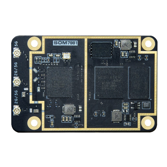
- Page 4 SOM7981 USER MANUAL 1. Introduction SOM7981 is an advanced System on Module (SoM) equipped with a MediaTek® MT7981BA processor and a powerful Wi-Fi 6 dual-band radio. This compact SOM blends a high-performance CPU with an extended-range radio module, making it perfect for Wi-Fi and IoT applications.
- Page 5 SOM7981 USER MANUAL 2. Hardware The module is built around MT7981BA and MT7976C. 2.4G+5G 2.4G+5G WiFi Antenna1 WiFi Antenna2 WiFi Antenna3 2412-2462MHz/ 2412-2462MHz/ 5180-5825MHz 5180-5825MHz 5180-5825MHz Y3 40MHz www.OpenEmbed.com...
- Page 6 SOM7981 USER MANUAL 3. Interface The following sections list the interfaces available on the SoM7981 and details the module pins used to interact with and control each interface. See the MT7981BA Data Sheet and Reference Manual for complete functional descriptions, programming guidelines and register listings for each of these blocks.
- Page 7 SOM7981 USER MANUAL 3.1 PINOUT of LEFT CONNECTOR(top view) PIN NO. Func.0 Func.1 Func.2 Func.3 Func.4 1.8V_OUT 1.8V_OUT 1.8V_OUT 1.8V_OUT 1.8V_OUT 1.8V_OUT SYS_RST# PCIE_RST# GPIO3 PCIE_RST# PCIE_CLKN PCIE_CLKP SSUSB_RXN SSUSB_RXP SSUSB_TXN SSUSB_TXP USB20_DM USB20_DP USB_VBUS GPIO14 USB_VBUS PWM1 WF5G_LED GPIO35...
- Page 8 SOM7981 USER MANUAL JTAG_JTRST# GPIO8 JTAG_JTRST# GBE_LED0 WO_JTDO GPIO9 WO_JTDO PCM_TX WO_JTDI GPIO10 WO_JTDI PCM_RX WO_JTMS GPIO11 WO_JTMS PCM_CLK WO_JTCK GPIO12 WO_JTCK PCM_FS WO_JTRST# GPIO13 WO_JTRST# PWM0 GBE_LED1 PCM_MCK 12V_IN SPI2_CS GPIO29 SPI2_CS UART1_RTS 12V_IN SPI2_MISO GPIO28 SPI2_MISO UART1_CTS 12V_IN...
- Page 9 3.3V_OUT Table2: Right connector 3.3 Power supply Signals When developing a carrier board for SOM7981,the power supply signals should be considered first. All GND signals should be connected to system ground directly. 12V_IN , main power supply of the module.
- Page 10 SOM7981 USER MANUAL 3.4 System Signals 3.4.1 SYS_RST# It is a directional, open drain signal, pulled up to the 3.3V_OUT. The signal is used as global module reset. When driven low by the carrier board, it reset the whole module.When module power sequence is complete,it can be used as carrier board supply enable, used to ensure proper power on/off sequencing between module and carrier board power supplies,an 4.7kΩ...
- Page 11 SOM7981 USER MANUAL 3.4.3 EthernetS The MT7981BA integrates an Ethernet PHY internally with 10/100/1000 BASE-T IEEE 802.3 compliant . Name Direction Description NET1_TRXP0 Bidirectional MDI MDI Data0 NET1_TRXN0 NET1_TRXP1 Bidirectional MDI MDI Data1 NET1_TRXN1 NET1_TRXP2 Bidirectional MDI MDI Data2 NET1_TRXN2...
- Page 12 SOM7981 USER MANUAL 4.Electrical specifications 4.1 Recommended Operation Conditions Symbol Comments Typical Uint 12V_IN Main power supply 3.3V_OUT Main 3.3V power out put 1.8V_OUT Main 1.8V power out put I/O pins Other GPIO with specified -0.3 Note: 1. All GPIO pins should be powered after VDD_3V3_OUT 2.
- Page 13 End product labeling: The final end product must be labeled in a visible area with the following: "Contains Transmitter Module FCC ID: 2BKE9-SOM7981". Information that must be placed in the end user manual: The OEM integrator has to be aware not to provide information to the end user regarding how to install or remove this RF module in the user's manual of the end product which integrates this module.
- Page 14 2.8 Label and complianceinformation Host product manufacturers need to provide a physical or e-label stating "Contains FCC ID:2BKE9-SOM7981"with their finished product. 2.9 Information on test modes and additional testingrequirements Data transfer module demo board can control the EUT work in RF test mode at specified test channel.
- Page 15 SOM7981 USER MANUAL FCC STATEMENT : This device complies with part 15 of the FCC Rules. Operation is subject to the following two conditions: (1) this device may not cause harmful interference, and (2) this device must accept any interference receivedincluding interference that may cause undesired operation.Any changes or modifications not...
Need help?
Do you have a question about the SOM7981 and is the answer not in the manual?
Questions and answers