Advertisement
Quick Links
© ELECTROLUX HOME PRODUCTS
ITALY S.p.A.
Spares Operations Italy
Corso Lino Zanussi, 30
I - 33080 PORCIA /PN (ITALY)
Fax +39 0434 394096
Edition: 2006-04
SOI/TD - PR
Publication no.
599 37 82-86
EN
1/37
SERVICE MANUAL
DISHWASHERS
Dishwasher with
EDW 1500 electronic
control system
(Functionalities)
DIVA 60 cm
Prod. N. 911 516 xxx
F.S. - Free-standing
Prod. N. 911 526 xxx
B.I. - Partially integrated
Production:
PLV - Zarow (Poland)
599 37 82-86
Advertisement

Related Manuals for Electrolux DIVA 911 516 Series


Summary of Contents for Electrolux DIVA 911 516 Series
- Page 1 SERVICE MANUAL DISHWASHERS Dishwasher with EDW 1500 electronic control system © ELECTROLUX HOME PRODUCTS Publication no. (Functionalities) ITALY S.p.A. Spares Operations Italy DIVA 60 cm Corso Lino Zanussi, 30 Prod. N. 911 516 xxx I - 33080 PORCIA /PN (ITALY) 599 37 82-86 F.S.
- Page 2 SOI/TD - PR 2/37 599 37 82-86...
- Page 3 CONTENTS Purpose of this manual ........................... 5 PRECAUTIONS ............................5 GENERAL CHARACTERISTICS......................5 CONTROL PANEL..........................6 Control panel............................6 4.1.1 ON/OFF button (S0)............................7 4.1.2 Programme/Option buttons (S1-S6)......................7 4.1.3 Indicator LEDs (LD7÷LD12) ........................7 4.1.4 Display ................................8 Options..............................8 4.2.1 “ 3 in 1 Tablet”.............................8 4.2.2 Extra rinse (rinse +).............................8 4.2.3...
- Page 4 Alarms ..............................24 10.1 Table of alarms..........................24 USER MODE ............................26 11.1 Regeneration levels ........................26 11.2 Rinse aid function.......................... 27 11.3 Activating/disactivating the buzzer....................27 Diagnostics mode / Options ........................28 12.1 Accessing diagnostics mode......................28 12.2 Reading the alarms and activating the individual components............ 28 12.3 Cancelling alarm codes from memory / Testing the LEDs............
- Page 5 1 Purpose of this manual The purpose of this Service Manual is to provide Service Engineers, who already have the basic knowledge necessary to repair household dishwashers, with technical information regarding dishwashers featuring the EDW1500electronic control system. These appliances are manufactured at Zarow (Poland). The EDW1500 control system consists of a main circuit board and a control/display board.
- Page 6 4 CONTROL PANEL 4.1 Control panel The configuration of the control panel depends on the following: Typology of the electronic board: horizontal buttons vertical buttons Number of programme selection buttons (from a minimum of 3 to a maximum of 6) Number of LEDs (max.13) Position of the ON/OFF button (right or left) Version with horizontal buttons...
- Page 7 4.1.1 ON/OFF button (S0) The ON/OFF button is featured on all models in the range, and is used to switch the appliance on and off. Switching off does not cancel the programme being executed. 4.1.2 Programme/Option buttons (S1-S6) The functions of the various buttons depend exclusively on the software configuration of each appliance, which can feature from 3 to 6 buttons.
- Page 8 4.1.4 Display The display, which consists of 2,5 digits, can indicate: The indicative time-to-end of the programme in minute. The countdown is carried out every minute and updated at the end of each programme phase (when the programme is updated it can decrease by more minutes at a time or stop for longer).
- Page 9 4.2.5 Delayed start Proceed as follows to select the delayed-start time: 1. Close the door and switch the appliance on by means of the S0 button. 2. Press the button repeatedly to select the delayed-start time which appears flashing on the display. The time increases every hour up to 19h [ ..19 0..
- Page 10 4.3.2 Modifying a programme 1. Until a cycle has actually started (digit with flashing light), the settings selected can be modified at any time by pressing the appropriate buttons. 2. To modify a programme that has already started, first cancel it (see corresponding parag) and then perform the new selections.
- Page 11 4.6 Sequence of operations 1. Close the door. Press S0 to switch the appliance on 2. Select the desired programme. The display shows the time-to-end or the programme no. flashing. The phase LEDs light up. 3. Within 3 seconds select the possible delayed start or the desired option (if featured) 4.
- Page 12 5 HIDRAULIC CIRCUIT 5.1 Version with short tank 1 - Fill hose 11 - Anti-overflow pressure switch 2 - Fill hose with Acquacontrol 12 - Sump assembly 3 - Fill solenoid 13 - Wash pump 4 - Regeneration solenoid 14 - Tube-enclosed heating element 5 - Air-Break 15 - Drain pump 6 - Steam condenser...
- Page 13 5.2 Version with long tank 1 - Fill hose 11 - Anti-overflow pressure switch 2 - Fill hose with Acquacontrol 12 - Sump assembly 3 - Fill solenoid 13 - Wash pump 4 - Regeneration solenoid 14 - Tube-enclosed heating element 5 - Air-Break 15 - Drain pump 6 - Steam condenser...
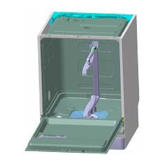
- Page 14 6 STRUCTURAL CHARACTERISTICS This range of dishwashers, compared to the previous version, has a simplified hydraulic circuit, a new plinth (structural and aesthetical part) and side panels as shown in the following pictures: Closed side panel Plastic part Aesthetical part SOI/TD - PR 14/37 599 37 82-86...
- Page 15 7 ELECTRICAL COMPONENTS AND THEIR FUNCTIONS 7.1 EDW1500 Electronic control system The EDW1500 control system consists of a main circuit board and a control/display board. Both boards are housed in a plastic container. Version with horizontal buttons Version with vertical buttons 7.1.1 Functions of the circuit board DISPLAY BOARD...
- Page 16 7.2 Specifications for actuators and sensors 7.2.1 Components TYPE OF ELECTRONIC TYPE OF COMPONENT POWER AVAILABLE CONTROL Wash pump Max 250W Triac Drain pump Max 100W Triac Heating element Max 2100W Relay Water fill solenoid Max 10W Triac Regeneration solenoid Max 10W Triac Detergent and Rinse-aid solenoid...
- Page 17 7.3 Power supply and programme selection The main board is powered by the closure of contacts 1-3 and 2-4 of the ON/OFF button (PU). The connectors used in this case are A2 (neutral) and B1 (line). The control/display board (user interface) is powered at 5V by the main board, making programme selection possible.
- Page 18 7.5.2 Dynamic fill The dynamic fill is obtained by switching on the washing pump whose rotation causes the pressure switch to switch to EMPTY. Subsequently, the fill solenoid valve is energized and water is introduced until the switch returns to FULL. The speed of rotation of the motor determines the quantity of water introduced, since the electronic control system switches on the washing pump at a variable speed which depends on the washing system that will be performed in the phases subsequent to the water fill:...
- Page 19 The washing pump is actioned by an asynchronous motor with a start-up capacitor (3µF - 450VL). The washing pump rotates in a counter-clockwise direction (seen from the impeller side) and is fitted with a tachometric generator. In order to optimize the washing programmes, two washing systems can be applied: “ctrl“...
- Page 20 7.11 Drain The drain pump (PS) is powered by triac TY3 (connector C1) and via the contacts of the ON/OFF switch (PU) and the door switch (IP). At the end of the drain phase, a control procedure is performed to check that the contact of the level pressure switch is open on EMPTY.
- Page 21 7.13 Resin washing Washing of the resins contained in the softening system is performed at the beginning of each washing cycle. In practise, the solution of salty water (regeneration water) remains deposited in the resin container from the end of the last completed cycle until the subsequent cycle. If the regeneration level is set to [10], washing of the resins is performed once at the beginning of the washing cycle and then again immediately after the regeneration process performed at the end of the washing phase.
- Page 22 ACTIVE-DRY TURBO-DRY 8.1.1 “Turbo-dry” drying Certain models feature a forced-air drying system. The steam is drawn in by the fan located inside the upper duct and routed towards the condenser in the fill tank, from which it returns to the tub through the steam venting ring. The fan motor (MV) is powered by triac TY6 (connector D3 on the circuit board) and by the contacts of the ON/OFF switch (PU) and the door switch (IP).
- Page 23 9 Automatic cycle 9.1 Turbidity sensor Certain models which feature the turbidity sensor may also feature a special “automatic” programme which optimizes the cycle according to the size of the load and the degree of soiling. This sensor is positioned externally to the sump, in direct contact with the water.
- Page 24 10 Alarms In the event that an abnormal situation should occur which might affect the correct operation of the appliance, the circuit board causes a safety system to intervene. In most cases, this interrupts the washing cycle. The last three alarm conditions are stored in memory. Using a special procedure available only to Service Engineers, it is possible to read all the alarms stored in memory.
- Page 25 Displayed Type of Display to the Description of the alarm condition Machine status Possible causes alarm user Heating element faulty; intervention of safety Heating Time-out The programme continues to the thermostats (open); wiring faulty; NTC sensor (poor (the check takes place every 3 minutes: end without heating (the washing thermal contact);...
- Page 26 11 USER MODE This procedure can be used to: • modify regeneration levels • activate or not rinse aid function • activate or not the buzzer 11.1 Regeneration levels 1. Cancel any cycles that may have been selected. 2. Press key S0 to switch the appliance on. 3.
- Page 27 11.2 Rinse aid function This function is active all the time. Only in case of “3in1” option setted up this function is not activated. If the drying results are not good, with “3in1” option setted up, is it possible to activate rinse aid function using the procedure described below.
- Page 28 12 Diagnostics mode / Options A single procedure can be used by Service Engineers to access the diagnostics system. After accessing diagnostics mode, the Engineer can: • read / cancel the alarms, • check for correct operation of the various components of the appliance, •...
- Page 29 12.3 Cancelling alarm codes from memory / Testing the LEDs It is good practise to cancel the alarm codes after reading the alarm code or after effecting repairs to check whether it is repeated during the diagnostics test. 1. Access diagnostics mode 2.
- Page 30 12.5 Options available to Service Engineers In particular circumstances, i.e. if the user reports unsatisfactory washing results, a special procedure, available only to Service Engineers, can be used to select two supplementary options designed to improve performance: • Extra cold rinse. •...
- Page 31 12.5.2 Disabling pulse washing Certain programmes use the pulse washing system (PW). Using the procedure described below, the Service Engineer can modify this system so that Ctrl (continuous) washing is used in all those programmes which normally use the PW system. This intensifies the washing action even in delicate programmes. Deactivation/activation mode 1.
- Page 32 13 ELECTRICAL FUNCTIONS 13.1 Electrical circuit diagram SOI/TD - PR 32/37 599 37 82-86...
- Page 33 13.2 Basic circuit diagram 13.2.1 Key to circuit diagram CO = Capacitor PA = Anti-overflow pressure TAC/T = Tachometric generator AR = Orange MR = General terminal block NE = Black DD = Detergent/ Rinse-aid switch TS = Safety thermostat BI = White MV = Fan motor RO = Pink...
- Page 34 14 Table of programmes The table below lists the phases of the programmes for this type of appliance. As these can be configured differently, refer to the relative documentation for the specific cycles available for each model. Programmes Pre-wash Wash Cold Rinse Hot rinse Type...
- Page 35 15 Checking the efficiency of the components In order to facilitate the control procedure for the components to be tested, a TEST PROCEDURE has been created which indicates the point to which the probes of the tester should be applied and the correct theoretical value for each component tested.
- Page 37 16 QUICK GUIDE TO THE SPECIAL FUNCTIONS The table below briefly describes how each of the special functions available to the user and to the Service Engineer can be used. Function Activation of the function Starting the function Brief description / Comments Keys Led(s) Keys...
Need help?
Do you have a question about the DIVA 911 516 Series and is the answer not in the manual?
Questions and answers