
Related Manuals for Hotstart OSA


Summary of Contents for Hotstart OSA
- Page 1 216351-000 rev1 INSTALLATION & OPERATION MANUAL O I L C I R C U L AT I N G H E AT I N G S Y S T E M F O R H A Z A R D O U S L O C AT I O N S MODEL...
- Page 2 & installation operation manual osa heating system...
-
Page 3: Identifying Your System
IDENTIFYING YOUR SYSTEM IOM216351-000 The HOTSTART heating system is designed to heat fluids for use in marine propulsion, diesel-powered generator sets, locomotives, gas compression or any large-engine applications. The system is pre-wired, pre-plumbed and assembled on steel plate. Each heating system has an identification plate which includes the part number and serial number. -
Page 4: Important Safety Information
IMPORTANT SAFETY HOTSTART recommends that a power switch or circuit breaker be located near the heating system INFORMATION for safety and ease of use. • Flameproof joints: Flameproof joints are not intended to be repaired in the field. Do not attempt... -
Page 5: Table Of Contents
Local/Off/Remote Switch | 3.2.3 Reset button/Motor Protection Switch (MPS) | 3.2.4 Pressure Gauge | HEATING SYSTEM START-UP | 3.3.1 First Run Procedure | MAINTENANCE AND TROUBLESHOOTING | SYSTEM FAULTS | 4.1.1 Oil Faults | & installation operation manual osa heating system... - Page 6 (this page intentionally left blank) & installation operation manual osa heating system...
-
Page 7: Overview
OVERVIEW WARNING System location classification: Before installing the OSA heating system, ensure all system components are suitable for the intended installation location by referring to the location classification labeling attached to the individual system components. HEATING SYSTEM COMPONENTS NOTE: Component illustrations are for reference only and are not to scale. See part drawings for dimensions and specifications. -
Page 8: Operation Overview
OPERATION OVERVIEW The OSA heating system is intended to maintain optimal oil temperature while the engine or compressor is shut down. The heating system may be activated locally or by optional remote control (see SECTION 2.5.2). The OSA heating system must be deactivated upon engine or compressor start-up. -
Page 9: Installation
If the pump is installed above the minimum oil level, a check valve must be installed. Isolation valves: Hotstart recommends installing full-flow ball valves to isolate the heating system in order to perform service on the system or engine without draining the oil. -
Page 10: Oil Plumbing Installation
OIL PLUMBING INSTALLATION 2.1.2 OIL RETURN 2.1.1 OIL SUPPLY When installing the OSA oil return line, refer to the following Hotstart guidelines: Installing a short, straight oil supply line with a minimum • of flow restriction is the most important step toward At a minimum, size the oil return line per the ensuring heating system longevity. -
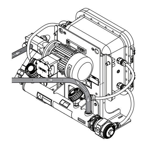
Page 11: Oil Plumbing Illustration (Compressor)
SECTION 2.1.2 OIL SUPPLY SECTION 2.1.1 COMPONENT DESCRIPTION USER SUPPLIED CHECK VALVE USER SUPPLIED FULL FLOW ISOLATION VALVE OIL PUMP OIL HEATING ELEMENT USER SUPPLIED FULL FLOW ISOLATION VALVE OPTIONAL USER SUPPLIED PRV & installation operation manual osa heating system... - Page 12 OIL SUPPLY ISOLATION VALVES SECTION 2.1.1 OIL RETURN SECTION 2.1.2 COMPONENT DESCRIPTION USER SUPPLIED CHECK VALVE USER SUPPLIED FULL FLOW ISOLATION VALVE OIL PUMP OIL HEATING ELEMENT USER SUPPLIED FULL FLOW ISOLATION VALVE & installation operation manual osa heating system...
-
Page 13: Mounting
Class Class Class Class Size 2/0 AWG 120 in · lbs Figure 4. Mount OSA unit in orientation shown. Do not mount at an 120 in · lbs angle or in any other orientation. 120 in · lbs ~133 ~259... -
Page 14: Customer Interface Connections
Main power terminal block Remote On/Off Figure 6. Main power supply and customer interface connections 24 V DC shutdown as shown in the OSA control box. Reference electrical schematic Main power ground drawing for proper wiring locations; the following illustrations are terminal block Fault signal typical customer interface locations. -
Page 15: Components And Operation
11 12 13 14 A2- 13 14 A2- Figure 7. OSA motor protection switch (left), showing stop/off (A) and reset/on (B) buttons. To reset the MPS, the heating system must MPS1 be switched off and either the reset button or the MPS reset/on button must be pressed. -
Page 16: Interface Components
TCR1 to unexpectedly, resulting in harmful or fatal electrical the desired temperature setting. Hotstart shock. recommends a control temperature on TCR1 of 104 °F (40 °C). The high-limit temperature setting on TCR2 should be set at 194 °F (90 °C). -
Page 17: Maintenance And Troubleshooting
Magnetic contactors are used as voltage switching switch must be switched to and then back remote controls for motors and heating elements in Hotstart to either to resume operation. local remote heating systems. The contactors use 120 volt or 240 A failure in the pump motor that causes the motor volt coils. -
Page 18: Temperature Control Relay
TCR1 TCR2 shock. Figure 8. Control (TCR1) and high-limit (TCR2) TCR showing If the OSA heating system does not maintain the desired 11 12 11 12 terminals T1, T2 and T3. preset control temperature or signals a high-limit 13 14 A2-... -
Page 19: Recommended Maintenance
If your pump motor has provisions for relubrication, refer to the pump motor manufacturer’s relubrication recommendations. Refer to the pump motor nameplate for lubrication type. & installation operation manual osa heating system... -
Page 20: Troubleshooting
Element contactor failed Check contacts and coil. Replace if necessary. Motor contactor failed Check contacts and coil. Replace if necessary. Control TCR failure: open Check and replace if necessary. See SECTION 4.2.9. & installation operation manual osa heating system...
Need help?
Do you have a question about the OSA and is the answer not in the manual?
Questions and answers