Advertisement
Quick Links
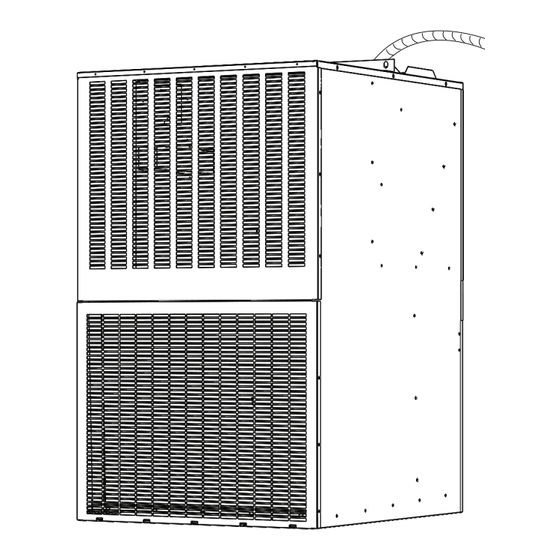
COMFORT
PACK
Installation Guide
Comfort Pack Gas
Universal
Non Condensing Furnace
80% AFUE
This unit should be installed in an
Outside Wall For
Thru-The-Wall
Installation Only!
Read Installation Manual
Prior To Starting The Installation.
Please fill in the following information and file it for
future reference.
MODEL NO.______________________________
SERIAL NO.______________________________
INSTALL DATE ___________________________
This manual must be left with the homeowner for future reference.
National Comfort Products
A Division of National Refrigeration and Air Conditioning Products, Inc.
539 Dunksferry Road • Bensalem, PA 19020-5908
(800) 523-7138
www.nationalcomfortproducts.com
Thru-the-Wall Comfort
Heating & Cooling
CP8
Universal
R454B
Go Thru-the-Wall
Advertisement

Related Manuals for NCP Thru-the-Wall Comfort CP850928UA


Summary of Contents for NCP Thru-the-Wall Comfort CP850928UA
- Page 1 Thru-the-Wall Comfort COMFORT PACK Heating & Cooling Installation Guide Comfort Pack Gas Universal Non Condensing Furnace 80% AFUE This unit should be installed in an Outside Wall For Thru-The-Wall Installation Only! Read Installation Manual Prior To Starting The Installation. Universal R454B Please fill in the following information and file it for future reference.
- Page 2 Installation Guide | Comfort Pack Universal with 80% Gas Heat Table of Contents Comfort Pack Nomenclature ............... page 3 Safety Warnings ..................page 4 Before You Start ..................page 7 Installation ....................page 8 Drainage ...................... page 8 Clearance ....................page 9 Unit Location Considerations ..............
- Page 3 Installation Guide | Comfort Pack Universal with 80% Gas Heat Comfort Pack Nomenclature Product Heat Type Refrigerant Clg. Capacity Htg. Capacity Series Generation Option Factory Use CP = Comfort Pack 8 = 80% Gas 5 = R454B 09 = 0.75 Ton 28 = 28 MBH U = Universal A = Standard...
- Page 4 Installation Guide | Comfort Pack Universal with 80% Gas Heat Safety Warnings! WARNING This appliance is not intended for use by those (including children) with reduced physical, sensory or mental capabilities, or lack of experience For your safety, do not store or use gasoline or other flammable and knowledge, unless they have been given supervision or instructions vapors and liquids in the vicinity of this or any other appliance.
- Page 5 Installation Guide | Comfort Pack Universal with 80% Gas Heat WARNING WARNING HIGH VOLTAGE! Disconnect ALL power before servicing. Do not use means to accelerate the defrosting process or to clean, Multiple power sources may be present. Failure to do so may other than those recommended by the manufacturer.
- Page 6 Installation Guide | Comfort Pack Universal with 80% Gas Heat WARNING WARNING Improper installation, adjustment, alteration, service, or maintenance These instructions are intended as an aid to qualified, licensed service can cause property damage, personal injury or loss of life. Refer to the personnel for proper installation, adjustment and operation of this unit.
- Page 7 Installation Guide | Comfort Pack Universal with 80% Gas Heat Before You Start CAUTION This unit is shipped with a cooling chassis installed in the cabinet. Prior to installing the unit in the wall opening, the shipping bolts located at the The installation of this appliance must conform to the requirements of bottom on both sides of the cabinet must be removed to allow for removal the National Fire Protection Association;...
- Page 8 Installation Guide | Comfort Pack Universal with 80% Gas Heat Installation TO INSTALL THE CHASSIS INTO THE CABINET: Turn off power to the unit. Temporarily secure the chassis power and control wiring and turn off power to the unit. Temporarily secure the chassis power WARNING and control wiring and connectors to the top of the indoor coil cover to prevent damage during chassis installation.
- Page 9 Installation Guide | Comfort Pack Universal with 80% Gas Heat clearance around the supports to route return ductwork to the unit or allow Secondary Drain Trap Install Instructions: for unrestricted airflow in an open return configuration. To reduce the possible transmission of sound and vibration, a resilient material such as 1.
- Page 10 The less resistive these grilles are to air flow, the better the units performance will be. Outdoor louvers provided by others must be approved by NCP to maintain unit performance and warranty. Care must be taken to locate the condenser Minimum 12"...
- Page 11 Installation Guide | Comfort Pack Universal with 80% Gas Heat Vent Termination Clearances for Direct Vented Installations in the USA For other gas venting information see page 19. Balcony - with perpendicular side wall Inside Corner Detail Combustible & Noncombustible X = 24”...
- Page 12 Installation Guide | Comfort Pack Universal with 80% Gas Heat Electrical Electrical - High Voltage All wiring must be installed in accordance with applicable codes. NOMINAL MINIMUM MAXIMUM The unit is factory wired for 230/1/60 power. For 208/1/60 power systems, VOLTAGE VOLTAGE VOLTAGE...
- Page 13 Installation Guide | Comfort Pack Universal with 80% Gas Heat High Voltage Power Supply WARNING Install a separate disconnect LIVE ELECTRICAL COMPONENTS! switch at the location of the Comfort Pack unit. During installation, testing, servicing and troubleshooting of this product, it may be necessary to work with live electrical components. Failure to follow all electrical safety precautions when exposed to live electrical components could result in death or serious injury.
- Page 14 Installation Guide | Comfort Pack Universal with 80% Gas Heat DSI Control Identification FAN OUTPUT- FAN OUTPUT- INDUCER FAN INPUT COOLING HEATING RELAY NEUTRALS SPARK IGNITOR OUTPUT MOLEX TO 24VAC, 60Hz., .5A MAX. ANSI Z21.20 AUTOMATIC HEAT COMPONENTS VOLTAGE COMMON All units are equipped with a temperature activated manually reset switch.
- Page 15 Installation Guide | Comfort Pack Universal with 80% Gas Heat Comfort Pack Dimension Drawing 31 1/2" 7 5/8" 3 13/16" 16" SUPPLY 1 1/4" 28" AIR OPENING 28" JUNCTION BOX 7 5/8" 31 17/32" JUNCTION BOX 7 21/32" 1 3/4" 16"...
- Page 16 Installation Guide | Comfort Pack Universal with 80% Gas Heat Gas Furnace Specifications Sequence of Operations (Gas Heat) Gas Heat – The cabinet includes a gas furnace with integral flue duct, direct 1. Call for Heat – The thermostat sends a call for heat therefore energizing spark ignition, safety controls, and operating controls.
- Page 17 Installation Guide | Comfort Pack Universal with 80% Gas Heat Abnormal Functions High Altitude Operation • Interrupted Thermostat Call for Heat – If the thermostat demand for heat If the heater is being installed at an elevation above 2000 ft. (610m), the is removed before the flame is recognized, the control will run the venter input rate will have to be derated.
- Page 18 Installation Guide | Comfort Pack Universal with 80% Gas Heat Derating by Valve Outlet Pressure Adjustment 4. With the heater operating determine that the inlet pressure to the heater for natural gas is between 5 and 13.5 inches w.c., and for propane between for High Altitude Operation Instructions 10 and 13.5 inches w.c.
- Page 19 Installation Guide | Comfort Pack Universal with 80% Gas Heat Gas piping external to the unit must include: a manual shutoff WARNING valve with 1/8" NPT plugged tapping (for test gauge connection), drip leg and ground union fitting. All components of a gas supply system must be leak tested prior to If the supply air from the unit is ducted to space(s) outside the placing equipment in service.
- Page 20 Installation Guide | Comfort Pack Universal with 80% Gas Heat Valve Outlet Gas Pressure Setting CAUTION Measuring valve outlet gas pressure cannot be done until the heater is in operation. Normally adjustments should not be necessary to the factory Route the wires so that they do not contact the flue gas collection box or preset regulator (also, see paragraph on high altitude operation).
- Page 21 Installation Guide | Comfort Pack Universal with 80% Gas Heat Combustion Air Proving Switch WARNING The combustion air proving switch is a pressure sensitive switch that monitors air pressure to ensure that proper combustion air flow is The operating valve is the prime safety shutoff. All gas supply lines available.
- Page 22 Installation Guide | Comfort Pack Universal with 80% Gas Heat Heater Start-Up 5. Wait five (5) minutes to clear for any gas. Then smell for gas, including near the floor. If you smell gas, STOP! and follow the steps in the WARNINGS above or on the Operating Label on the heater.
- Page 23 At all times, NCP maintenance and service guidelines shall be followed. If in Il en résulte une combustion incomplète qui produit du monoxyde de doubt, consult NCP’s technical department for assistance.
- Page 24 Installation Guide | Comfort Pack Universal with 80% Gas Heat The indoor blower motor and the outdoor fan motor have permanently 5. No person carrying out work in relation to a REFRIGERATING SYSTEM which lubricated bearings and do not require routine service. The refrigeration system involves exposing any pipe work shall use any sources of ignition in such a is sealed and factory charged with R454B so that routine maintenance is not manner that it may lead to the risk of fire or explosion.
- Page 25 Installation Guide | Comfort Pack Universal with 80% Gas Heat 4. Pump down refrigerant system • Clean all dirt, lint, and grease from the combustion air openings and venter motor. 5. Make sure that cylinder is situated on the scales before recovery takes place.
- Page 26 Installation Guide | Comfort Pack Universal with 80% Gas Heat Inspect the Heat Exchanger Inspect and Clean the Burner Remove the heat furnace baffle panel (see page 29). Remove any dirt or dust With the burner assembly removed, shine a flashlight on the burner ribbons. accumulation.
- Page 27 Installation Guide | Comfort Pack Universal with 80% Gas Heat Burner Orifice Venter Motor and Wheel Assembly Burner orifice only needs to be replaced when a change in gas is made. When Remove dirt and grease from the motor casing. Venter motor bearings are ordering a replacement orifice, give BTU/H content and specific gravity of permanently lubricated.
- Page 28 Installation Guide | Comfort Pack Universal with 80% Gas Heat Pressure Switch Troubleshooting If it is determined that the pressure switch needs replacing, use only the Check the DSI Integrated Control Module (Circuit Board) - The Integrated factory-authorized replacement part that is designed for this heater. For Circuit Board monitors the operation of the heater and includes an LED approximate location see Figure 5.
- Page 29 Installation Guide | Comfort Pack Universal with 80% Gas Heat Directions to Slide Out the Furnace (After removing front panels) 3. Remove (2) right side screws and remove the front 1. Remove the (4) screws indicated at the right furnace baffle. Gas Line Front Furnace...
- Page 30 Installation Guide | Comfort Pack Universal with 80% Gas Heat Power Cord Pull Forward 4. Unplug (2) molex plugs before slid- ing out the heat exchanger/furnace assembly. 5. Grasp the vertical heat exchanger “partition” firmly with your left hand. Lift Be careful not to tear the side and bottom insulation when pulling the 6.
- Page 31 Installation Guide | Comfort Pack Universal with 80% Gas Heat Performance Data Up to 12.5 SEER2 - 80% AFUE Shipping Nominal Cooling Sensible Charge Heater Input Heater Output Model SEER2 Weight Cooling Tons Btu/h Btu/h R-454B (Oz.) (Btu/h) (Btu/h) (lbs) CP850928UA 0.75 8,900...
- Page 32 Installation Guide | Comfort Pack Universal with 80% Gas Heat Check Your Temperature Rise *Example shown has a ducted return The temperature rise should be as follows 28MBTU = 52.5°F Nominal (45°F to 60°F) 38MBTU = 52.5°F Nominal (45°F to 60°F) 51MBTU = 55°F Nominal (45°F to 65°F) 64MBTU = 67°F Nominal (60°F to 80°F) In order to calculate CFM use the formula...
- Page 33 Installation Guide | Comfort Pack Universal with 80% Gas Heat Comfort Pack Gas CFM and Temperature Rise 28,000 BTU Input UNIT SIZE COLOR SPEED .1" w.c. .2" w.c. .3" w.c. .4" w.c. .5" w.c. 27.3 27.8 28.4 29.0 29.6 Yellow 31.9 32.4 32.9...
- Page 34 Installation Guide | Comfort Pack Universal with 80% Gas Heat Comfort Pack Gas CFM and Temperature Rise 51,000 BTU Input UNIT SIZE COLOR SPEED .1" w.c. .2" w.c. .3" w.c. .4" w.c. .5" w.c. 49.7 50.7 51.8 52.8 54.0 Yellow 58.1 59.0 60.0...
- Page 35 Installation Guide | Comfort Pack Universal with 80% Gas Heat Air Flow Data ESP (in. wc) / CFM Model Color Speed Tap Yellow CP8509**UA Blue Black Orange Yellow CP8512**UA Blue Black Orange Yellow CP8518**UA Blue Black Orange Yellow CP8524**UA Blue Black Orange...
- Page 36 Installation Guide | Comfort Pack Universal with 80% Gas Heat TEST HEAT COOL 24V FAN...
- Page 37 Installation Guide | Comfort Pack Universal with 80% Gas Heat DSI INTEGRATED CONTROL MODULE CONTROL GREEN LED STATUS STEADY ON Normal operation, no call for heat FAST FLASH Normal operation, call for heat 1 FLASH In lockout from failed ignition or flame loss 2 FLASH Pressure switch does not close for 240 seconds 3 FLASH...
- Page 38 Installation Guide for Comfort Pack (CPG 95TE) Units Installation Guide | Comfort Pack Universal with 80% Gas Heat TROUBLSHOOTING PROBLEM PROBABLE CAUSE REMEDY No power to unit Turn power, check supply fuses or circuit breaker Venter motor will not start No 24 volt power to integrated circuit board.
- Page 39 Installation Guide | Comfort Pack Universal with 80% Gas Heat Replacement Parts Guide To assure accuracy when ordering replacement parts, please provide the following information: EXAMPLE: Unit Model: Serial #: Part #: Replacement Parts Guide | Cabinet and Furnace Parts Cabinet Parts Furnace Parts Part Number...
- Page 40 Installation Guide | Comfort Pack Universal with 80% Gas Heat Replacement Parts Guide | Chassis Parts Part Number Part Description 0.75 Ton 1.0 Ton 1.5 Ton 2.0 Ton Chassis Model Base Pan 142-56-067 142-56-067 142-56-070 142-56-070 Indoor Coil 142-08-392 142-08-392 142-08-396 142-08-396 Outdoor Coil...
- Page 41 Installation Guide | Comfort Pack Universal with 80% Gas Heat IMPORTANT!!! BEFORE REMOVING A WARRANTY COMPRESSOR, PLEASE FILL OUT THE FOLLOWING AND CALL (800) 523-7138. REMOVAL OF COMPRESSOR WITHOUT FACTORY VERIFICATION CAN LEAD TO WARRANTY CREDIT BEING DENIED Incoming Voltage to Compressor at Contactor is:__________Volts Compressor Starting AMP Draw:__________ Ω...
- Page 42 Installation Guide | Comfort Pack Universal with 80% Gas Heat NATIONAL ® COMFORT PRODUCTS HEATING & A/C EQUIPMENT A Division of National Refrigeration & Air Conditioning Products, Inc. 539 Dunksferry Road | Bensalem, PA 19020 | 215-244-1400 | 1-800-523-7138 COMFORT PACK LIMITED WARRANTY 1.
- Page 43 All compressors must be securely bolted, banded, and stretch wrapped to a skid in the upright position. B. Parts. All other returned parts must be securely packaged and clearly marked with its corresponding RMA number provided from NCP.
- Page 44 National Comfort Products A Division of National Refrigeration and Air Conditioning Products, Inc. 539 Dunksferry Road | Bensalem, PA 19020-5908 (800) 523-7138 www.nationalcomfortproducts.com 14291157 IM CP8 Gas Heat 12/5/2024...
Need help?
Do you have a question about the Thru-the-Wall Comfort CP850928UA and is the answer not in the manual?
Questions and answers