
Summary of Contents for revvity Pre-NAT II SY61-01
- Page 1 Pre-NAT II Automated Workstation ( ) SY61-01 User Manual 2023-11-30 (Date of Issue) 2023-11-30 (Data of revision) SYQ01573-15-D(en)
- Page 2 Font Usage In the contents, the Notes, Warnings and Reminders are highlighted in “bold and italic” font. The function keys and menu points that need a single mouse click are highlighted in “bold” font. NOTES The instrument meets the requirements for emissions and immunity in accordance with the EN 61326-1 Electrical Equipment for Measurement, Control and Laboratory Use - EMC Requirements - Part 1: General Requirements &EN 61326-2-6 Electrical Equipment for Measurement, Control and Laboratory Use - EMC Requirements - Part...
- Page 3 No.115, North Tai Ping Road, Taicang Economic Development Zone, 215400 Jiangsu Province, PEOPLE’S REPUBLIC OF CHINA Tel: (86)(10) 8919-4387 Email: Quality.TaiCang@REVVITY.COM Symbol Explanation Caution: Indicates that caution is necessary when operating the device or control close to where the symbol is placed, or that the current situation needs operator awareness or operator action in order to avoid undesirable consequences.
- Page 4 Consult instructions for use or consult electronic instructions for use: Indicates the need for the user to consult the instructions for Importer: Indicates the entity importing the medical device into the locale Distributor: Indicates the entity importing the medical device into the locale Model number: Indicates the model number or type number of a product...
- Page 5 The instrument is equipped with a robotic arm, which is a moving part during operation. Do not reach inside the area involving the moving robotic arm using either bare hands or other objects! Manual operation of the robotic arm is also not permitted! All parts of the instrument should be considered as contamination sources.
- Page 6 CONTENTS CHAPTER I. INSTRUMENT DESCRIPTION ................4 MANUAL DESCRIPTION ....................4 PRODUCT NAME ....................... 4 PRODUCT MODEL ......................4 DESIGN ..........................4 DESCRIPTIONS OF FUNCTIONAL MODULES .............. 6 ..........................6 VERVIEW ......................7 RODUCT PPEARANCE ..................8 AYOUT OF THE ONTROL YSTEM .....................
- Page 7 Barcode scanning ......................18 6.6.3 INSTRUMENT INSTALLATION ..................18 ......................18 VERALL NSTALLATION ................... 19 NSTALLATION OF OMPONENTS CHAPTER II. INSTRUCTIONS ....................21 DIAGRAM OF INSTRUMENT USE ................. 22 SWITCH ON/OFF THE INSTRUMENT ................23 ..........................23 WITCH .......................... 23 WITCH PREPARATION .........................
- Page 8 ..........................40 11.6 SSISTANT ..................41 11.7 OTES ARNINGS AND EMINDERS ..........42 11.8 OMMON ALFUNCTION NALYSIS AND ROUBLESHOOTING MAINTENANCE ........................ 44 SHIPPING & STORAGE ....................44 OTHER ..........................45 & E ............... 45 14.1 ANUFACTURING XPIRATION ........................45 14.2 OMPONENTS ......................
- Page 9 Chapter I. Instrument Description Manual Description This manual describes how to operate the Automated Workstation. Each chapter gives a full description of the design/product features. Users are required to read the User Manual carefully to understand all functions and accurate operation of the device. Please use the instrument as described or the protection provided by the instrument may be disabled.
- Page 10 Sleeve pickup Figure 1. The process of nucleic acid extraction.
- Page 11 Descriptions of Functional Modules Overview The Automated Workstation consists of liquid handling module, barcode read module, heating module, reagent, and consumables placement module, a nucleic acid extraction module, a control system and software. An overview of the instrument is shown in Figure 2. Reagent and Liquid Handling Barcode Read...
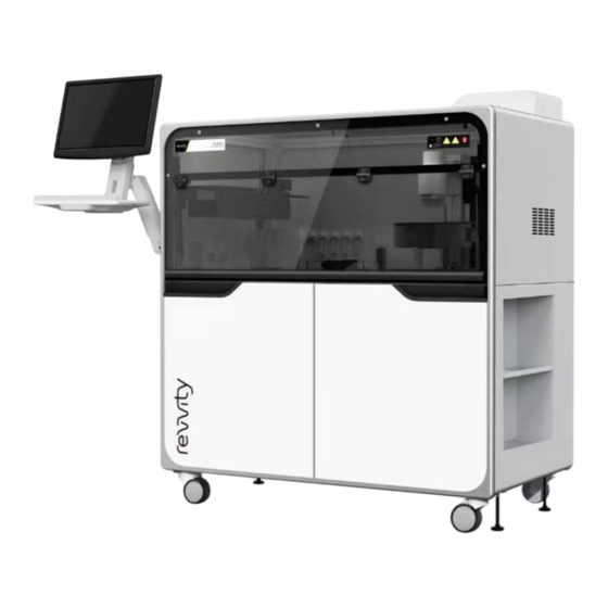
- Page 12 Product Appearance Interface of Power Supply / Signal Lower-Left Door Lower-Right Door Front Door Figure 3 Product appearance...
- Page 13 Layout of the Control System Heating Module Barcode Read Module Sample Loading Module Control Panel Nucleic Acid Extraction Power Supplies Module Control System Figure 4Layout of control system Note: To prevent short circuits, perfusion of conductive liquid must be avoided due to the centralized placement design of the primary system control boards in the instrument.
- Page 14 Z Direction Figure 5. Liquid Handling module. Nucleic Acid Extraction Module The nucleic acid extraction module consists of a Z-axis slide, a 96-extraction head, and a magnetizer. The Z-axis slide facilitates the Z-direction movement of the 96-extraction head using a stepper motor. The 96 magnetic rods of the 96-extraction head can achieve high-speed rotation (max.
- Page 15 Extraction Rod Heads Electromagnetic Coil Dispenser Module Rotary Working Platform Figure 6 Nucleic acid extraction module The magnetic rods of the nucleic acid extractor perform up and down movements through the z-axis slide. The extraction process includes 8 steps: 1. The Rod Head move down and pick up the sleeves automatically. 2.
- Page 16 4. The magnetic rods with attracted magnetic beads then move from the extraction plate and insert into washing plate A for washing. When the magnetic field is off, the magnetic beads fall into washing plate A. The magnetic rods spin at a high-speed during washing to facilitate the contact of the nucleic acids attached to the magnetic beads with the washing buffer.
- Page 17 The liquid tube connection of Dispenser Module. The function of the dispenser module is to dispense the buffers from reagent tanks into the deep well plates. Tube numbers are ordered on the manifold shown as (tube 1,2,3 Figure 7-2 front, 4,5,6 rear manifold) Liquid Tube of Dispenser Module Labels of Dispenser Tubes Figure 7-1 Dispenser module...
- Page 18 Figure 7-2 Barcode Read Module Figure 8Barcode reader...
- Page 19 Heating Module Figure 9Heating Module Power Input/Output The interface consists of CAN connectors, a power outlet and a master switch as shown in Figure 10 Either CAN1 or CAN2 Master Switch should be connected to PC CAN card RS232 Serial Port should be connected to PC serial port Power Outlet...
- Page 20 5.10 Software Software Name: Pre-NAT II For software introduction and detailed instructions, please refer to Chapter II. 5.11 Intended Use of the Product The product is intended to be used for dispensing serum / plasma / other samples and extracting nucleic acids, so that the outcome can be used for PCR tests or other molecular biology tests.
- Page 21 2) Range of sample aspiration volume: 4µL-800µL 3) Sample tubes: φ12-16mm x 100mm/75mm 4) Software operation environment Operation system: Win10 Hardware configuration: CPU 3.0GHz and above RAM: 4G and above Hard drive: 160G and above 5) Outer size of the instrument (length x width x height): 1510mm×845mm×1690mm 6)...
- Page 22 Environmental Impacts of Waste The instrument is equipped with a specific tip container to collect used tips. The tips should not be reused and must be collected after use for disposal to avoid environmental contamination. The dilution tanks and the deep-well plates for reagents or samples should not be reused and must be collected after use for disposal to avoid environmental contamination.
- Page 23 insufficient Range of sample aspiration 4μL-800μL volume ADP carry over None contamination Sample aspiration Accuracy of α volume (X) sample 4µL≤X≤20µL ≤±5% aspiration 20µL<X≤800µL ≤±2% Sample aspiration Precision of volume (X) sample 4µL≤X≤20µL ≤5% aspiration 20µL<X≤800µL ≤2% 6.6.3 Barcode scanning The instrument is equipped with an automatic barcode scanner.
- Page 24 and check that no damage has occurred during shipping. Remove the bottom fixation components of the crate and the instrument. Use a forklift to lift the instrument from the rear side and place the instrument on flat ground. Lock the brake on the wheel after placing the instrument at the target location.
- Page 25 The computer and monitor selected by the user must comply with the requirements of the "IEC 60905 Information Technology Equipment - Safety ", i.e. must have a ECertificate that meets the requirements of IEC 60905. Power cord connection The power supply cable of the instrument should be a 3-pin 16A/250V power supply cable, which connects to the master power outlet on the panel behind the instrument.
- Page 26 Chapter II. Instructions Wearing latex gloves when performing any procedures on the Pre-NAT II system is strongly recommended. The waste tank and the sensors in contact with the liquid should be considered as contamination sources! If the instrument is operated without following the instructions, there is a possibility of damaging the protection provided by the instrument.
- Page 27 Diagram of Instrument Use Properly connect the instrument, computer, and the monitor Switch on the master power supply of the instrument, the computer, and the monitor Open the Pre-NAT II software Enter the Pre-NAT II operation interface Initialize instrument successfully Choose required test protocol Load step by step following software instructions...
- Page 28 Switch On/Off the Instrument Switch On Switch on the master power supply of the Pre-NAT II. Turn on the computer and the monitor. Open the software. Warning: Before switching on the power supply for the first time, make sure that the fixation component of the robotic arm is removed, or it may damage the motor.
- Page 29 sources! To prevent biohazards and chemical hazards, wear protective gloves for operation at all times. Personnel must be trained in protection measures against biohazards and chemical hazards. 11 Usual Operation of Pre-NAT II Software Warning: Personnel without proper training from Suzhou Sym-Bio Lifescience Co., Ltd.
- Page 30 Figure 12Main interface of software After entering the standard operation interface of the Pre-NAT II, the system will automatically prompt the user to [Initialize the device] Select the [Yes] button, as shown in Figure 13. Figure 13 The instrument will start to home all modules and will indicate when initialization is completed, as shown Figure 14.
- Page 31 Figure 14 11.2 Enter Test Protocol. The following is an example of a test protocol. As the test protocols may be different from the example, the sample loading information may be different. Read the figures and text information provided by the software wizard carefully when operating the instrument. After system initialization, click on the[Project Input] button on the interface as shown in Figure 15.
- Page 32 Zone B Zone A Figure 15 Zone A: Protocol item selection zone. Select the protocol, e.g.SWRelease_Test_EAP, as shown in Figure 16. Figure 16 Zone B: Edit sample loading zone. Select [Beginning Step] from the drop-down list, as shown in Figure17, normally use the default setting. The sample positions can be...
- Page 33 customized by the user as needed. After defining the sample positions, click the [Sample Input] and then [Input Complete] buttons. The system will automatically prompt the user about the positions of the samples and whether the sample input is correct. Figure 17 ...
- Page 34 Figure 18 11.2.3 Load the Tips After entering the tip loading interface, the user can load different types of tips into the locations as shown in Figure 19. After completion of loading, click on the [Next] button. Figure 19...
- Page 35 11.2.4 Load Elution Buffer and Beads enter barcode Load the troughs based on the configuration shown in Figure 20. After loading, of the extraction kit, click on the [Next] button. Figure 20 11.2.5 Load the PCR Reaction Tubes After entering the PCR reaction tube loading interface, load the consumables based on the wizard information shown in Figure 21.
- Page 36 Figure 21 11.2.6 Load PCR Reagent Load reagent tubes into the corresponding locations based on the configuration shown in Figure Figure 22...
- Page 37 11.2.7 Load the Nucleic Acid Extraction Consumables After entering the nucleic acid extraction loading interface, load the consumables based on the wizard information shown in Figures 23&24. After loading, click on the [Next] button. Figure 23:Load disposable tips for the rod head Figure 24:Load deep well plates...
- Page 38 11.2.8 Load Samples and Scan Barcodes After entering the sample loading interface, load the sample racks into the corresponding guide bars based on the wizard information. After loading, click on [Start Load]. The loading wizard information is shown in Figures 25 - 27. The barcode scanning is performed as follows: 1.
- Page 39 Figure 26 Figure 27 11.2.9 Load Extraction Reagent Containers The device is not equipped with a weight detection feature, which senses the volume of reagent in the buffer containers. So, the reagent volume in the container will be monitored...
- Page 40 artificially, it is a better way to calculate the whole reagent volume required according to the sample size before experiment. 11.3 Run the Instrument After loading, the system will enter into the operation interface as shown in Figure 28. Click on the [Run] button.
- Page 41 Figure 29...
- Page 42 11.3.1 Operation Interface Figure 30 Load/Unload: To control the loading and unloading processes for the consumables, reagents and samples Run/Pause: To run or suspend the procedure Stop: To abort the run Assistant: To configure assisting features in this tab ...
- Page 43 11.4 Unload After the run is completed, unload the instrument following the message provided by the software. Click on the [Unload] button as shown in Figures31-33. Figure 31 Figure 32...
- Page 44 Click [Begin Unload] to unload the instrument. Figure 33 11.5 Maintenance In the [Maintenance] menu, the two primary functions liquid tube cleansing and UV light control are shown as in Figure 34.
- Page 45 Figure 34 Select the liquid tube cleansing function as needed. After selection, choose the tubes that are to be cleaned in the "ChooseManifold" option. Click on [Start Flush]. The timing for cleansing can be setup by the user. Click on the [Exit] button to exit the tube cleansing function.
- Page 46 Figure 35 11.7 Notes, Warnings and Reminders 1) If the power supply has been switched off and is then required again, wait 5 seconds before switching it onto avoid causing an abnormal server discharge and a subsequent malfunction. 2) If a malfunction occurs, follow instructions from the software interface. 3) If a malfunction occurs that cannot be addressed by the user, discontinue the operation immediately and inform the technician.
- Page 47 robotic arm is completely stopped. 8) Do NOT modify or change the system settings without training and authorization. 9) Do NOT change or increase the instrument capacity as it is set by the engineer. 10) When the UV light is turned on, keep away from the instrument. 11) Clean the instrument on a regular basis.
- Page 48 bottom during sample aspiration. Check that the tips are 1ADP Tips are Tip is not picked up properly picked up, by 23010 lost or absent tightly, or is loose or lost checking if the liquid drops after aspiration.
- Page 49 12 Maintenance 1) Keep the instrument surroundings clean. 2) During normal stand-by status, keep internal platforms for samples, reagents and dispensing clean. The tip disposal bin must be kept empty and free of foreign objects. The internal surface must be sterilized and cleaned using disinfectant (e.g.,84 disinfectant in 1: 50 dilution).
- Page 50 an ambient temperature of -10℃–55℃ and a relative humidity no more than 93%, and without direct exposure to sunlight or rain or exposure to any erosive chemicals or hazardous gases. Optimally, the storage life should normally not be longer than 6 months. Instrument can be operated normally when the environmental conditions meet the requirements specified in this manual.
- Page 51 Accessory Box III (Computer Dell w/ package, w/o SY17180224 battery) Accessory box I-parts list Description Part No. Unit MSM I calibration plate SY10310075 PCR Holder SY10310010 Tip Holder SY10310076 900ul TIP SY55093 175ul TIP SY55092 Rack Set 360/96 (7 DWP + 1 Sleeve Ada) SY10380131 USB drive SY17180100...
- Page 52 CAN Communication Line SY22520043 Serial port line SY22530500 Power strip - EU version SY22420034 Ashbin SY14120246 Wireless mouse keyboard w/o battery SY17180113 Displayer SY17180178 Blood Sample tube Adapter SY10380125 Reagent holder SY11380088 Fuse SY12840017 Tip chute SY11380028 Channel, tip chute to ash bin SY11380082 96 rod heads w/ package CMG-536...
- Page 53 European standard cable SY22530590 φ0.45 Needle SY17180032 Waste liquid bucket SY4142 ChiTaS sample holder SY11300202 Tip debug Jig SY10380161 Tip height debug Jig SY10380162 14.3 After-Sales Service If the instrument malfunctions, you can report it to our company by phone. Describe the malfunction in detail so that the engineer from the After-Sales Service Department can give proper technical consultation and directions accordingly and determine the required service for the malfunction (door-to-door service or shipping).
- Page 54 No.115, North Tai Ping Road, Taicang Economic Development Zone, 215400 Jiangsu Province, PEOPLE’S REPUBLIC OF CHINA. After-Sales Unit: Country Customer Care Phone Email USCAN.RHLotReservation@revvity.com USCAN.RRInventoryControl@revvity.com USCAN.ScheduledOrders@revvity.com USCAN.Customs@revvity.com USCAN.InternalOrders@revvity.com USCAN.InstrumentReturns@revvity.com 800-762-4000 USCAN.Non- InstrumentReturns@revvity.com USCAN.CustomerMaster@revvity.com USCAN.EDIOrder@revvity.com USCAN.Manualinvoices@revvity.com USCAN.DealPricing@revvity.com USCAN.EmailedInvoices@revvity.com cc.UKIE.sales@revvity.com Ireland 1800 93 28 86 cc.UKIE.service@revvity.com...
- Page 55 Finland (358)0800 117186 cc.nordic.service@revvity.com cc.nordic.sales@revvity.com Norway 800 18 854 cc.nordic.service@revvity.com cc.france.sales@revvity.com France 0805-111-333 cc.france.service@revvity.com 0800-40858 (BE) cc.benelux.sales@revvity.com Belgium 0800-26588 (LU) cc.benelux.service@revvity.com cc.benelux.sales@revvity.com Netherlands (31) 0800 0234490 cc.benelux.service@revvity.com 0800-000015 (SALES) cc.dach.sales@revvity.com Switzerland 0800-001125 (SERVICE) cc.dach.service@revvity.com 0800-1810032 (SALES) cc.dach.sales@revvity.com Germany 0800-0006679 (SERVICE) cc.dach.service@revvity.com...
- Page 56 Philippines, ccsvmxsg@revvity.com ausales@revvity.com ccsvmxau@revvity.com Zealand, cc.au@revvity.com Taiwan cc.tw@revvity.com cc.th@revvity.com Thailand 662-319-7901 # 312 ccsvmxth@revvity.com 6686-3993097 ausales@revvity.com Australia +61 (03) 9212 8500 ccsvmxau@revvity.com cc.au@revvity.com Hong Kong +852 26201881 cc.apac@revvity.com cc.jp.online@revvity.com Japan 045-339-5866 cc.jp.service.online@revvity.com South Korea (82) 2 868 5345 cc.KR@revvity.com 15 Product Warranty 15.1...
- Page 57 Malfunctions caused by hardware, software and consumables provided by companies other than ours. Malfunctions caused by inappropriate maintenance. Malfunctions caused by PCBA and component failure due to strong erosive gas in the air. 15.4 Right to Revise the User Manual The User Manual may be revised without advanced notice.
- Page 58 Appendix I Instrument Installation Diagram(unit:mm) Space for maintenance Space for Monitor Stand...
Need help?
Do you have a question about the Pre-NAT II SY61-01 and is the answer not in the manual?
Questions and answers