
Related Manuals for Esco S3 Series

Summary of Contents for Esco S3 Series
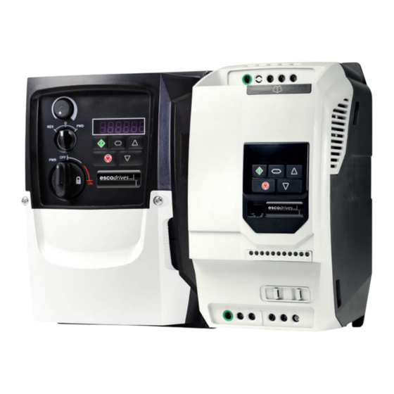
- Page 1 Product Manual Frequency Inverter S3 Series Single Phase Output IP20 & IP66 (NEMA 4X) 0,37 - 1,1kW...
-
Page 2: Table Of Contents
1. Quick Start Up ....... . 4 6. Parameters ....... 23 1. -
Page 3: General Information
User Guide Revision 2.02 esco antriebstechnik adopts a policy of continuous improvement and whilst every effort has been made to provide accurate and up to date information, the information contained in this User Guide should be used for guidance purposes only and does not form the part of any contract. -
Page 4: Quick Start Up
Do not attempt to carry out any repair of the escodrives. In the case of suspected fault or malfunction, contact your local esco Sales Partner for further assistance. 4 | escodrives EDS3 1Ph Output User Guide | Version 2.02... -
Page 5: Quick Start Process
1.2. Quick Start Process Step Action See section Page Identify the Enclosure Type, Model Type and ratings of 2. 1 . Identifying the Drive by Model Number your drive from the model code on the label. In particular - Check the voltage rating suits the incoming supply - Check the output current capacity meets or exceeds the full load current for the intended motor Unpack and check the drive. -
Page 6: Installation Following A Period Of Storage
1.3. Installation Following a Period of Storage 100% Where the drive has been stored for some time prior to installation, or has remained without the main power supply present for an extended period of time, it is necessary to reform the DC capacitors within the drive according to the following table before operation. - Page 7 Quick Start – IP66 Switched Switch the mains power on to the unit using the built in isolator switch on the front panel. The OFF/REV/FWD will enable the output. NOTE: With single phase motors, forward rotation only is possible. The potentiometer will control the motor shaft rotational speed. Version 2.02 | escodrives EDS3 1Ph Output User Guide | 7...
-
Page 8: General Information And Ratings
2. General Information and Ratings This chapter contains information about the escodrives EDS3 including how to identify the drive. 2.1. Identifying the Drive by Model Number Each drive can be identified by its model number, as shown in the table below. The model number is on the shipping label and the drive nameplate. -
Page 9: Mechanical Installation
3. Mechanical Installation 3.1. General T h e escodrives should be mounted in a vertical position only, on a flat, flame resistant, vibration free mounting using the integral mounting holes or DIN Rail clip (Frame Sizes 1 and 2 only). ... -
Page 10: Guidelines For Enclosure Mounting - Ip20 Units
T he enclosure design and layout should ensure that the adequate ventilation paths and clearances are left to allow air to circulate through the drive heatsink. esco recommend the following minimum sizes for drives mounted in non-ventilated metallic enclosures: Recommended Above &... -
Page 11: Mechanical Dimensions - Ip66 (Nema 4X) Enclosed Units
3.5. Mechanical Dimensions – IP66 (NEMA 4X) Enclosed Units Weight Drive Size 9. 1 3 6.34 6.37 7.44 148.5 5.85 10. 1 2 7. 1 6 7.87 7.00 Mounting Bolts Tightening Torques Frame Size Metric Frame Size Required Torque Terminal Type All Sizes Control Terminals 0.5 Nm... -
Page 12: Guidelines For Mounting (Ip66 Units)
3.6. Guidelines for mounting (IP66 Units) B efore mounting the drive, ensure that the chosen location meets the environmental condition requirements for the drive shown in section 10. 1 . Environmental. T he drive must be mounted vertically, on a suitable flat surface. -
Page 13: Removing The Terminal Cover
Mains switch-disconnector Lock Off On the switched models the mains switch-disconnector can be locked in the ‘Off’ position using a 20mm standard shackle padlock (not supplied). IP66 / NEMA 4X Unit Lock Off 3.8. Removing the Terminal Cover To access the connection terminals, the drive front cover needs to be removed as shown. IP66 / NEMA 4X Units Removing the screws on the front of the product allows access to the connection terminals, as shown below. -
Page 14: Power & Control Wiring
4. Power & Control Wiring 4.1. Connection Diagram 4.1.1. IP20 & IP66 (NEMA 4X) Non-Switched Units 4.1.2. IP66 (NEMA 4X) Switched Units Sec. Page Protective Earth (PE) Connection Incoming Power Connection Fuse / Circuit Breaker Selection 4.3.2 Optional Input Choke 4.3.3 Optional External EMC Filter 4. -
Page 15: Protective Earth (Pe) Connection
4.2. Protective Earth (PE) Connection Grounding Guidelines The ground terminal of each escodrives should be individually connected DIRECTLY to the site ground bus bar (through the filter if installed). escodrives ground connections should not loop from one drive to another, or to, or from any other equipment. Ground loop impedance must conform to local industrial safety regulations. -
Page 16: Motor Connection
4.3.3. Optional Input Choke A n optional Input Choke is recommended to be installed in the supply line for drives where any of the following conditions occur: o The incoming supply impedance is low or the fault level / short circuit current is high. o The supply is prone to dips or brown outs. -
Page 17: Using The Selector Switch
4.7. Using the Selector Switch (Versions With Local Controls Only) By adjusting the parameter settings the escodrives can be configured for multiple applications. This could typically be for Hand/Off/Auto applications (also known and Local/Remote) for HVAC and pumping industries. The integrated switch operates in parallel with drive terminal 2 (T2) and terminal 3 (T3) as digital input 1 and digital input 2. -
Page 18: Control Terminal Connections
4.7.3. Using the Internal Pot (Local Control Versions Only) On switched drives, the built-in pot (indicated) may be used to directly control the signal level applied to analog input 1, and therefore the output frequency (motor speed). To select the built-in pot as the signal source for analog input 1, set P-16 = 8 In-pot. -
Page 19: Motor Thermal Overload Protection
4.9. Motor Thermal Overload Protection 4.9.1. Internal Thermal Overload Protection The drive has an in-built motor thermal overload function; this is in the form of an “I.t-trP” trip after delivering >100% of the value set in P-08 for a sustained period of time (e.g. 150% for 60 seconds). 4.9.2. -
Page 20: Optional Brake Resistor
Allow a minimum of 10 minutes discharge after power off before attempting any connection to these terminals. Suitable resistors and guidance on selection can be obtained from your esco Sales Partner. The brake transistor is enabled by setting P-34 > 0. See section 6.2. Extended Parameters on page 26 for more information. -
Page 21: Operation
5. Operation 5.1. Managing the Keypad The drive is configured and its operation monitored via the keypad and display. Used to display real-time information, to access and exit NAVIGATE parameter edit mode and to store parameter changes. Used to increase speed in real-time mode or to increase parameter values in parameter edit mode. -
Page 22: Read Only Parameter Access
5.4. Read Only Parameter Access Press and hold the Use the up and Press the Navigate Use the up and Press the Navigate Press and hold the Navigate key > 2 down keys to select key for <... -
Page 23: Parameters
6. Parameters 6.1. Standard Parameters Par. Description Minimum Maximum Default Units P-01 Maximum Frequency / Speed Limit P-02 500.0 50.0 (60.0) Hz / RPM Maximum output frequency or motor speed limit – Hz or RPM. If P-10 >0, the value entered / displayed is in RPM. P-02 Minimum Frequency / Speed Limit P-01... -
Page 24: Extended Parameters
6.2. Extended Parameters Par. Description Minimum Maximum Default Units P-15 Digital Input Function Select Defines the function of the digital inputs depending on the control mode setting in P-12. See section 7. Analog and Digital Input Macro Configurations for more information. P-16 Analog Input 1 Signal Format See Below... -
Page 25: Analog Output Mode
Par. Description Minimum Maximum Default Units P-25 Analog Output Function Select Digital Output Mode. Logic 1 = +24V DC 0: Drive running. Logic 1 when the escodrives is enabled (Running). 1: Drive healthy. Logic 1 When no Fault condition exists on the drive. 2: At speed. -
Page 26: Serial Communications Configuration
Par. Description Minimum Maximum Default Units P-31 Keypad Start Mode Select This parameter is active only when operating in Keypad Control Mode (P-12 = 1 or 2) or Modbus Mode (P-12 = 3 or 4). When settings 0, 1, 4 or 5 are used, the Keypad Start and Stop keys are active, and control terminals 1 and 2 must be linked together. Settings 2, 3, 6 and 7 allow the drive to be started from the control terminals directly, and the keypad Start and Stop keys are ignored. - Page 27 Par. Description Minimum Maximum Default Units P-40 Index 1: Display Scaling Factor 0.000 16.000 0.000 Index 2: Display Scaling Source Allows the user to program the escodrives to display an alternative output unit scaled from either output frequency (Hz), Motor Speed (RPM) or the signal level of PI feedback when operating in PI Mode. Index 1: Used to set the scaling multiplier.
-
Page 28: Read Only Status Parameters
Par. Description Minimum Maximum Default Units P-63 Modbus Mode Selection 0: Standard. All Modbus RTU telegrams are valid regardless of the destination address. Communication loss timeout will activate when no valid Modbus RTU message is present within the time limit set in P-36. 1: Advanced. -
Page 29: Single Phase Motor - Boost Starting Cycle
Description Explanation Par. P00-32 Actual PWM switching frequency (kHz) Actual switching frequency used by drive P00-33 Critical fault counter – O-I These parameters log the number of times specific faults or errors occur, and are useful for diagnostic purposes P00-34 Critical fault counter –... -
Page 30: Analog And Digital Input Macro Configurations
7. Analog and Digital Input Macro Configurations 7.1. Overview escodrives EDS3 uses a Macro approach to simplify the configuration of the Analog and Digital Inputs. There are two key parameters which determine the input functions and drive behaviour: P-12 Selects the main drive control source and determines how the output frequency of the drive is primarily controlled. P-15 Assigns the Macro function to the analog and digital inputs. -
Page 31: Macro Functions Guide Key
7.3. Macro Functions Guide Key The table below should be used as a key on the following pages. Function Explanation STOP Latched Input, Open the contact to STOP the drive Latched input, Close the contact to Start, the drive will operate as long as the input is maintained FWD... -
Page 32: Macro Functions - Terminal Mode (P-12 = 0)
7.4. Macro Functions – Terminal Mode (P-12 = 0) DI3 / AI2 DI4 / AI1 P-15 Diagram STOP No Function AI1 REF P-20 REF Analog Input AI1 STOP AI1 REF PR-REF P-20 P-21 Analog Input AI1 STOP P-20 - P-23 P-01 P-20 P-21... -
Page 33: Macro Functions - Keypad Mode (P-12 = 1 Or 2)
7.5. Macro Functions - Keypad Mode (P-12 = 1 or 2) DI3 / AI2 DI4 / AI1 P-15 Diagram STOP ENABLE INC SPD DEC SPD No Function STOP ENABLE PI Speed Reference INC SPD DEC SPD STOP ENABLE KPD REF... -
Page 34: Macro Functions - User Pi Control Mode (P-12 = 5 Or 6)
7.7. Macro Functions - User PI Control Mode (P-12 = 5 or 6) DI3 / AI2 DI4 / AI1 P-15 Diagram STOP PI REF P-20 REF STOP PI REF AI1 REF Analog Input AI2 (PI Feedback) 3, 7 STOP PI REF P-20 E-TRIP AI1 (PI FB) -
Page 35: Modbus Rtu Communications
16 Write Multiple Holding Registers (Supported for registers 1 – 4 only) 8.3. RJ45 Connector Configuration CAN - For full MODBUS RTU register map information please CAN + refer to your esco Sales Partner. Local contacts can be 0 Volts found by visiting our website: -RS485 (PC) www.esco-antriebstechnik.de/EN... -
Page 36: Modbus Register Map
The Register number for each parameter P-04 to P-60 is defined as 128 + Parameter number, e.g. for parameter P-15, the register number is 128 + 15 = 143. Internal scaling is used on some parameters, for further details please contact your esco Sales Partner. - Page 37 8.4.1. Drive status and error code Word PDI0 Function When “0” Function When “1” In the event of a trip, the associated code is shown in this byte Bit 6: Drive Ready to Run is defined as: Not tripped. ...
-
Page 38: Can Communication
9. CAN Communication 9.1. CAN Communication The CAN communication profile in the escodrives EDS3 is implemented according to the specification DS301 version 4.02 of CAN in automation (www.can-cia.de). Specific device profiles such as DS402 are not supported. The CAN communication function is enabled by default after power up. However in order to use any control functions through CAN, the following setting is required: P-12 = 7 or 8. - Page 39 Objects No. Mapped Object Length Mapped Function Transmission Type 0006h Unsigned 16 Dummy 0006h Unsigned 16 Dummy PDO2 0006h Unsigned 16 Dummy 0006h Unsigned 16 Dummy 201 1h Unsigned 16 DC bus voltage 2012h Unsigned 16 Digital input status PDO2 2013h Integer 16 Analog input 1 (%)
- Page 40 Index Sub Index Function Access Type PDO Map Default Value RX PDO1 comms param. no. of entries 1400h RX PDO1 COB-ID 40000200h+Node ID RX PDO transmission type RX PDO2 comms param. no. of entries 1401h RX PDO2 COB-ID C0000300h+Node ID RX PDO2 transmission type RX PDO1 1 mapping / no.
-
Page 41: Both
9.2. Additional Information Relating to CAN or Modbus or Both 9.2.1 Drive Control Word Format High byte Low byte Bit 0: Run/Stop command: Set to 1 to enable the drive. Set to 0 to stop the drive. Bit 1: Fast stop request. Set to 1 to enable drive to stop with 2nd deceleration ramp. Bit 2: Reset request. -
Page 42: Technical Data
10. Technical Data 10.1. Environmental Operational ambient temperature range Open Drives : -10 … 50°C (frost and condensation free) Enclosed Drives : -20 ... 40°C (frost and condensation free) Storage ambient temperature range : -40 … 60°C Maximum altitude Open Drives : 2000m. -
Page 43: Additional Information For Ul Compliance
10.3. Additional Information for UL Compliance escodrives EDS3 is designed to meet the UL requirements. For an up to date list of UL compliant products, please refer to UL listing NMMS.E494838. In order to ensure full compliance, the following must be fully observed. Input Power Supply Requirements Supply Voltage 1 10 –... -
Page 44: Troubleshooting
11. Troubleshooting 11.1. Fault Code Messages Fault No. Description Suggested Remedy Code nF No Fault Not required. Brake channel over current Check external brake resistor condition and connection wiring. r Brake resistor overload The drive has tripped to prevent damage to the brake resistor. ...
Need help?
Do you have a question about the S3 Series and is the answer not in the manual?
Questions and answers