
Related Manuals for Endress+Hauser FWE200DH


Summary of Contents for Endress+Hauser FWE200DH
- Page 1 Products Solutions Services 8029845/YWL2/V2-0/2016-10 Operating Instructions FWE200DH Dust Measuring Device...
- Page 2 This work is protected by copyright. Any rights derived from the copyright shall be reserved for Endress+Hauser SICK GmbH+Co. KG. Reproduction of this document or parts of this document is only permissible within the limits of the legal determination of Copyright Law.
- Page 3 Safety information and protective measures ........ 9 Product description .................11 System features and application areas ............11 2.1.1 System features and advantages ..........11 2.1.2 Application areas ................11 FWE200DH operating principle ..............12 2.2.1 Functional principle ..............12 2.2.2 Isokinetic behavior ...............14 2.2.3 Scattered light measuring principle ..........14 2.2.4...
- Page 4 Installing the backpurge option (only necessary when ordered separately) ..................44 3.3.5 Connecting the remote unit option..........46 Start-up and configuration ..............47 Putting the FWE200DH into operation ............47 4.1.1 Preparatory work ................47 4.1.2 Starting the FWE200DH............... 48 4.1.3...
- Page 5 Warning and error messages in SOPAS ET ..........99 6.2.1 Measuring sensor .................99 6.2.2 Measuring system..............100 6.2.3 Control unit ................102 Endress+Hauser O P E R A T I N G I N S T R U C T I O N S 8029845/YWL2/V2-0/2016-10...
- Page 6 Consumable parts for 2-years operation ...........112 7.4.1 Measuring sensor...............112 7.4.2 Blower unit..................112 Annex.......................113 Standard settings FWE200DH ..............113 Endress+Hauser O P E R A T I N G I N S T R U C T I O N S 8029845/YWL2/V2-0/2016-10...
- Page 7 Refit any contact protection removed before switching the power voltage back on again. 1.1.3 Hazards through laser beam WARNING: Hazards through laser beam FWE200DH The sender/receiver unit of the FWE200DH uses a laser with laser class 2. ▸ Never look directly into the beam path ▸...
- Page 8 Otherwise – the device could become dangerous – the manufacturer’s warranty becomes void Restrictions of use The FWE200DH measuring system is not approved for use in potentially explosive ● atmospheres. Endress+Hauser O P E R A T I N G I N S T R U C T I O N S...
- Page 9 General information Designated users The FWE200DH measuring system may only be installed and operated by skilled techni- cians who, based on their technical training and knowledge as well as knowledge of the rel- evant regulations, can assess the tasks given and recognize the hazards involved.
- Page 10 Important information FWE200DH Recognizing malfunctions Every deviation from normal operation is to be regarded as a serious indication of a func- tional impairment. These are, amongst others: Warning indications ● Significant drifts in measured results ● Increased power consumption ●...
- Page 11 Product description System features and application areas The measuring system FWE200DH serves for continuously measuring dust concentrations up to 200 mg/m³ (typical range of application) in wet gases (temperatures below the dew point) with a resolution of up to approx. 0.1 mg/m³. It can be used in a wide range of appli- cations and features low installation effort and simple handling.
- Page 12 2.2.1 Functional principle The FWE200DH functions as a bypass system. A partial gas flow is suctioned from the gas duct via a sample gas probe, overheated in a thermo cyclone so that water drops and aerosols vaporize and then fed into a measuring cell. A laser beam passes through the sample gas in the measuring cell and the light scattered by the particles in the gas flow is measured by the receiver.
- Page 13 FWE200DH Product description Fig. 1: FWE200DH basic layout Measuring and control unit Duct A D P Sample gas probe Blower unit SOPAS ET operating software Base plate Power supply 115 / 230 V AC Heating band 1 Output signal 0 ... 20 mA...
- Page 14 FWE200DH 2.2.2 Isokinetic behavior The measuring behavior of the FWE200DH is mainly independent of gas velocity changes in the duct. Therefore an isokinetic extraction (extraction velocity = gas velocity) is not required. In standard state, the measuring system FWE200DH works with a stable volume flow between approx.
- Page 15 FWE200DH Product description Fig. 2: Measuring principle Laser diode Receiver Measuring volume Determining the dust concentration Measured scattered light intensity (SI) is proportional to dust concentration c. Scattered light intensity not only depends on the number and size of particles but also on the optical characteristics of the particles and therefore the measuring system must be calibrated using a gravimetric comparison measurement for exact dust concentration measurement.
- Page 16 Product description FWE200DH The function check comprises: Approx. 30 s measurement of zero value, control value and contamination of optical ● interfaces Every 90 s (standard value), output of values determined (duration parameter can be ● modified see “Setting the function check”, page 57).
- Page 17 FWE200DH Product description Control value measurement (span test) Sender beam intensity changes between 70 and 100% during control value determination. The light intensity received is compared against the standard value (70%). The measuring system generates an error signal for deviations greater than ±2%. The error message is cleared again when the next function check runs successfully.
- Page 18 Product description FWE200DH Device components 2.3.1 Sample gas probe The sample gas probe serves to extract and return the partial gas flow, It is fixed on a flange with tube (see “Flange with tube”, page 18) to be fitted onsite on the gas duct.
- Page 19 FWE200DH Product description 2.3.3 Extraction and return hoses Sample gas probe and control unit are connected with flexible hoses with NW32 for gas extraction and NW 50 for gas return. Standard length is approx. 1.2 m. In most cases, an active heating (option) is not required (available as an option). It is recommended to use an extraction hose with insulation for use outside with very low ambient temperatures and longer hoses.
- Page 20 (see “Setting standard parameters”, page 53). Depending on the function, three individual software modules are used (”FWE200DH” for system functions, ”DH SP200” for measuring functions and ”MCU” for input and output functions). The parameters are stored reliably even in the case of a power failure.
- Page 21 When in operation, the measuring and control unit is covered by a two-piece hood that also serves as weather protection for outdoor installations. The cover can be omitted for use in rooms. Fig. 9: Weatherproof cover for FWE200DH Type code The respective version of the measuring and control unit is marked by a type code:...
- Page 22 Product description FWE200DH 2.3.4.1 Thermo cyclone The thermo cyclone comprises a housing with insulation, a swirl chamber with inlet and out- let connections and 2 heating bands to overheat the partial gas flow. The inlet connection is fitted tangentially, creating a swirl flow in the swirl chamber. A PTFE nozzle in the inlet connection accelerates the flow.
- Page 23 FWE200DH Product description Fig. 11: Sample gas and purge air feed From thermo cyclone ( page 20, Fig. 8) Light trap To mixing tube in ejector ( page 20, Fig. 8) Sample gas (1) from the thermo cyclone flows down through measuring tube (2) vertically through laser beam (3).
- Page 24 Measured values and status messages are output on an LC-Display. It also allows configur- ing basic functions. The control unit is fitted in a steel sheet enclosure. Fig. 12: Control unit Processor boards for system control (”FWE200DH”) and data recording/ Display module processing and signal input/output (”MCU”) Fuses...
- Page 25 FWE200DH Product description Standard interfaces Analog outputs ● 3 outputs 0/2/4...22 mA (electrically isolated, active, min. 12-bit resolution) for output of scattered light intensity (corresponds to dust concentration not calibrated), dust concen- tration calibrated and dust concentration scaled Analog inputs ●...
- Page 26 Display alarm or error messages Menu Display main menu and selection of submenus After the measuring system has been switched on, the start phase of the FWE200DH is shown on the LC-Display during the warming up time (see “Starting the FWE200DH”, page 48).
- Page 27 FWE200DH Product description 2.3.5 Blower unit The blower unit serves to feed the sample gas into the measuring and control unit via the ejector. Air connection to the ejector is made via a flexible NW 25 hose. At the same time, a partial flow is delivered from the ejector to the measuring cell to keep the optical components clean.
- Page 28 Product description FWE200DH 2.3.6.2 Heated extraction hose In special applications (e.g. very low gas temperature and high gas humidity, very low ambi- ent temperatures, limitation of heating temperatures), it might be necessary to additionally heat the sampling line, see “Extraction and return hoses”, page 19).
- Page 29 FWE200DH Product description 2.3.6.4 Cover at the bottom This subassembly serves as additional protection of the measuring system at low ambient temperatures. It is installed on the base plate of the measuring and control unit and closes the weatherproof cover at the bottom.
- Page 30 SOPAS ET (PC program) SOPAS ET is a SICK software for easy operation and configuration of the FWE200DH. SOPAS ET runs on a Laptop/PC, which is connected to the FWE200DH via an USB line or Ethernet interface (option). The menu structure simplifies changing settings. Further functions are also available (e.g., data storage, graphic displays).
- Page 31 Provide platforms or pedestals as required openings Distances to measuring No mutual interference of calibration Plan sufficient distance between measur- level probe and FWE200DH ing and calibration level (approx. 500 mm) Plan the voltage Operating voltage, power According to Technical Data (see “Tech-...
- Page 32 Assembly and installation FWE200DH Assembly Carry out all assembly work onsite. This includes: ▸ Fitting the flange with tube ▸ Installing the measuring and control unit ▸ Installing the blower unit WARNING: ▸ Observe the relevant safety regulations as well as the safety notices in Sec- tion 1 during all assembly work.
- Page 33 FWE200DH Assembly and installation Fig. 18: Sample gas probe alignment Horizontal duct Vertical duct Flow direction Flow direction Flow direction Work to be performed ▸ Measure the fitting location and mark the installation location. ▸ Remove insulation (when fitted) ▸...
- Page 34 Assembly and installation FWE200DH Fig. 19: Assembly dimensions 150... Ø 14 Min. 15 ° Recommended position < 250 Alternative possible position Distance as large as required for probe installation Duct wall 3 = flange with tube Weatherproof cover open Clearance for Service (Dimensions in mm) Min.
- Page 35 FWE200DH Assembly and installation 3.2.3 Installing the blower unit Consider the following points when selecting the installation location: A level, vertical base at an easily accessible, protected location with clean air when pos- ● sible is required. The distance to the measuring and control unit must not exceed 10 m.
- Page 36 Assembly and installation FWE200DH Weatherproof cover for blower unit The weatherproof cover (see “Weatherproof cover for blower unit”, page 111) comprises a cover and locking set. Installation: ▸ Fit the locking pins from the locking set on the base plate.
- Page 37 For the power supply to the FWE200DH, a one-phase main supply voltage – 230 V AC 50/60 Hz with fuse min. 10 A or – 115 V AC 50/60 Hz with fuse min. 15 A must be available.
- Page 38 Fig. 22: Switch for supply voltage in the measuring and control unit Fig. 23: Control unit connections 1 Connection for Display module 6 System control processor board (FWE200DH) 2 Processor board for data recording/processing and signal 7 Connections for signal inputs and outputs...
- Page 39 6 Processor board for data recording/processing 12 Connections for digital inputs D15 to D18 (with and signal input/output (MCU) the extended calibration function option installed) 7 System control processor board (FWE200DH) p. 28, §2.3.6.3) 8 Connections for measuring sensor (DHSP200)
- Page 40 Assembly and installation FWE200DH Connections on processor board for data recording/processing and signal input/output (MCU) Terminal No. Connection Function Output relay 1 (operation/malfunction) n.c. n.o. Output relay 2 (maintenance) n.c. n.o. Output relay 3 (function check) n.c. n.o. Output relay 4 (maintenance request) n.c.
- Page 41 FWE200DH Assembly and installation Connections on processor board for system control (FWE200DH) Terminal No. Connection Function d in5 Digital input DI5 (calibration function switchover) Digital input DI6 (output contamination value on AO) d in6 Ground for DI5 and DI6 Digital input DI6 (output control value on AO)
- Page 42 Assembly and installation FWE200DH 3.3.2.2 Connecting the blower unit and supply voltage ▸ Check whether toggle (1) for voltage supply is set to the supply voltage present at the installation location; if not, switch accordingly. Fig 25 Switch for supply voltage in the blower unit...
- Page 43 FWE200DH Assembly and installation Fig. 26: Connecting the blower unit and supply voltage ▸ Connect the mains cable of blower unit (1) to corresponding terminals (2) in the control unit. ▸ Unscrew nut (3) from the PG screw fitting (belongs to control cable).
- Page 44 Assembly and installation FWE200DH 3.3.4 Installing the backpurge option (only necessary when ordered separately) Fit the backpurge subassembly onto the measuring and control unit ▸ Disconnect extraction hose (1) from connection of adapter (2), take the adapter off and loosen connection cable (3) to the control unit from measuring sensor (4).
- Page 45 FWE200DH Assembly and installation Connecting backpurge option ▸ Loosen the wires of connection cable (1) on plug-in connector (2), pull the cable through one of the rear PG screw fittings (3) and connect the wires, color correct, to the plug-in connector again.
- Page 46 Assembly and installation FWE200DH 3.3.5 Connecting the remote unit option Version without power supply unit ▸ Connect the connection cable to the measuring and control unit (4-wire, twisted pair, with shield) to the connections in the control unit (see “Control unit connections”, page 38) and the module of the remote unit.
- Page 47 Start-up and configuration Start-up and configuration Putting the FWE200DH into operation Prerequisite for performing the work described in the following is completion of the assem- bly and installation of measuring unit, control unit and blower unit according to Section 3.
- Page 48 Start-up and configuration FWE200DH 4.1.2 Starting the FWE200DH The start phase of the FWE200DH starts when the main supply voltage is switched on. The start process runs as follows: Function Marginal conditions Switch main supply voltage on ↓ Heating bands 1 and 2 of the thermo cyclone are heated up ↓...
- Page 49 FWE200DH Start-up and configuration 4.1.3 Fitting the sample gas probe WARNING: Danger from exhaust gas ▸ Only fit the sample gas probe on equipment with hazard potential (hot or aggressive gases, higher internal duct pressure) when the equipment is at a standstill.
- Page 50 Start-up and configuration FWE200DH Basics 4.2.1 General information Prerequisite for work described in the following is completion of the assembly and installa- tion as described in Section 3. Start-up and parameter setting comprise: Fitting and connecting the sender/receiver unit, ●...
- Page 51 FWE200DH Start-up and configuration 4.3.1.1 Finding the DUSTHUNTER COM port If you do not know the COM port: Use the Windows Device Manager to find the COM port (no administrator rights are needed). Disconnect the connection of the DUSTHUNTER and your laptop/PC.
- Page 52 Start-up and configuration FWE200DH 4.3.2 Connection to the device via Ethernet (option) To connect to the measuring system via Ethernet, the Ethernet interface module must be installed on the MCU (see “Device check accessories”, page 111) and the parame- ters set.
- Page 53 FWE200DH Start-up and configuration Setting standard parameters 4.4.1 Factory settings Parameter Value Sample gas Nominal value 160°C temperature Value for warning < 150 °C and > 180 °C Value for malfunction 130°C Differential pressure (flow monitoring) 0.8 hPa Function check Every 8 h;...
- Page 54 Start-up and configuration FWE200DH 4.4.2 Setting ”Maintenance” mode ▸ In SOPAS ET: Change to the ”Maintenance/Maintenance” directory in the respective device file, activate the checkbox ”Activate offline maintenance” in the window. Fig. 32: SOPAS ET menu: MCU/Maintenance/Maintenance ”Maintenance” mode can also be set using the buttons on the LC-Display of the control unit (see “Menu structure”, page...
- Page 55 FWE200DH Start-up and configuration 4.4.3 Changing function parameters Select device file ”FWE200DH” to change temperature and pressure settings and switch to directory ”Configuration / Application Parameter”. Fig. 33: SOPAS ET menu: FWE200DH/Configuration/Application parameters (example) 4.4.3.1 Change temperature settings In certain cases, it can be necessary to change the nominal value for sample gas tempera- ture (e.g., for acid dew point temperature >...
- Page 56 ● For setting, enter a value in window ”Limit pGas” in group ”Flow settings” (see “SOPAS ET menu: FWE200DH/Configuration/Application parameters (example)”, page 55) corre- sponding to approx. 33% of the differential pressure shown on the LC-Display after flow adjustment according to “Basics”, page...
- Page 57 FWE200DH Start-up and configuration 4.4.4 Setting the function check To change the values set at the factory (see “Factory settings”, page 53), select device file ”MCU” and switch to directory ”Adjustment / Function Check - Automatic”. The interval time, control value output on the analog output and the start timepoint for automatic func- tion check can be changed here.
- Page 58 Start-up and configuration FWE200DH 4.4.5 Setting the analog output parameters Select the ”Configuration / IO Configuration / Output Parameters” directory to set the ana- log outputs. Default values see “Factory settings”, page 53 ● In order to output the dust concentration under standard conditions ("Conc. s.c."...
- Page 59 FWE200DH Start-up and configuration Field Parameter Remark Analog Output Value on analog Conc. a.c. (SL) Dust concentration in operating state The selected measured 1 Parameter output 1 (based on scattered light intensity) variables are output on the analog output. Conc.s.c.dry O2 corr.
- Page 60 Start-up and configuration FWE200DH 4.4.6 Setting the analog input parameters Select the ”Configuration / IO Configuration / Input Parameters” directory to set the analog inputs. Fig. 36: SOPAS ET menu: MCU/Configuration/IO configuration/Input parameter Field Parameter Remark Temperature Source Constant Value A fixed value is used to calculate the scaled value.
- Page 61 FWE200DH Start-up and configuration Fig. 37: SOPAS ET menu: MCU/Parameters/Value Damping Field Parameter Remark Damping time Value in s Response time for the selected measured variable ( see “Response Sensor 1 time”, page Setting range 1 ... 600 s Endress+Hauser...
- Page 62 Start-up and configuration FWE200DH 4.4.8 Defining regression coefficients To change the values set at the factory (see “Factory settings”, page 53), select device file ”DH SP200” and switch to directory ”Configuration / Application Parameters”. Fig. 38: SOPAS ET menu: DH SP200/Configuration/Application parameter Two different functions, independent of each other, can be selected and configured in the windows ”Calibration coefficients for calculation of concentration with scattered light”...
- Page 63 FWE200DH Start-up and configuration 4.4.9 Calibration for dust concentration measurement NOTE: The steps described here serve to avoid input errors. Carrying out comparison ● measurements demands special knowledge that cannot be described in detail here. The calculation of regression coefficients cc2, cc1 and cc0 from coefficients K2, K1 ●...
- Page 64 Start-up and configuration FWE200DH Enter the regression coefficients There are two options: – Direct input of K2, K1, K0 in a measured value computer NOTE: In this case, the regression coefficients set in the sender/receiver unit and the measuring range set in the MCU may not be changed anymore. On the optional LC Display (when used), the dust concentration is displayed as uncalibrated value in mg/m³.
- Page 65 FWE200DH Start-up and configuration 4.4.10 Data backup All parameters relevant for the collecting, processing and input/output of measured values as well as current measured values can be saved in SOPAS ET and printed. This allows easy reentering of set device parameters as needed or registering device data and states for diagnostic purposes.
- Page 66 Start-up and configuration FWE200DH Fig. 40: Parameter protocol FWE200DH (example) Endress+Hauser O P E R A T I N G I N S T R U C T I O N S 8029845/YWL2/V2-0/2016-10...
- Page 67 FWE200DH Start-up and configuration 4.4.11 Starting measuring operation Set the measuring system to ”Measurement” mode after entering/modifying parameters. To do so, stop ”Maintenance” mode: Click checkmark ”Maintenance sensor” off. Fig. 41: SOPAS ET menu: MCU/Maintenance/Maintenance Standard start-up is now completed.
- Page 68 Start-up and configuration FWE200DH Setting the Interface module parameters The measuring system is delivered with an Interface module Modbus TCP as standard. When desired, it can be swapped for an Interface module for Profibus DP V0 or Ethernet (type 1) (see “Device check accessories”, page...
- Page 69 FWE200DH Start-up and configuration Switch to directory ”Configuration / I/O Configuration / Inter- face Module” directory and check that the interface is set according to Fig. “SOPAS ET menu: MCU/Configuration/IO configuration/Interface module” in the ”RS 485 Interface Parameter” field.
- Page 70 Start-up and configuration FWE200DH 4.5.1.2 Installing the configuration program A separate configuration program has to be installed to set the customer's requirements. Administrator rights are required to install software. System requirements Operating system: MS-Windows XP or higher ● Program NET Framework 4.0 ●...
- Page 71 FWE200DH Start-up and configuration 4.5.1.3 Integrating the Modbus module in the network ▸ Start the ”DeviceInstaller” program. Fig. 45: Starting the ”DeviceInstaller” ▸ Wait for a few seconds while the program is searching for installed components. ▸ Select the ”Tools/Options” menu.
- Page 72 Start-up and configuration FWE200DH ▸ Select the ”Device/Search” menu and search for the Modbus module. Fig. 48: Searching for connected components If no module has been found, check the network connection and search again. ▸ Select the found module. Fig. 49: Selecting the module NOTICE: Select the module only in the right window, not in the tree structure on the left.
- Page 73 FWE200DH Start-up and configuration ▸ Click the ”Assign IP” menu and perform the following steps. Fig. 50: Network assignment (address information is exemplary) Step Remark Select the respective setting depending on the desired address assignment (automatic or manual assignment) Manual assignment: Enter the required network connection data here.
- Page 74 Start-up and configuration FWE200DH Fig. 51: Defining the address settings ▸ Complete the assignment, then wait while the module is being configured and then click ”Finish”. Fig. 52: Completing the assignment Endress+Hauser O P E R A T I N G I N S T R U C T I O N S...
- Page 75 FWE200DH Start-up and configuration 4.5.1.4 Configuring the Modbus module ▸ After confirming the address assignment with ”Finish”, the following window is displayed: Fig. 53: ”Telnet Configuration” ▸ Perform steps (1) to (3) in succession and confirm with <Enter>. Fig. 54: ”Telnet Configuration”...
- Page 76 Start-up and configuration FWE200DH Fig. 55: Serial and Modbus settings Enter ‘2‘ Confirm with <Enter> or enter ‘1‘ Confirm with <Enter> or enter ‘2‘ Enter ‘3‘ (if already present, confirm with <Enter>) Confirm with <Enter> or enter ‘57600,8,N,1‘ Enter ‘3‘...
- Page 77 FWE200DH Start-up and configuration 4.5.1.5 Checking the functional capability ▸ Enter 'ping' followed by the IP address under ”Command Prompt” (”Start → Programs → Accessories”) and check the module reply. Fig. 56: Correct reply from Modbus module Endress+Hauser O P E R A T I N G I N S T R U C T I O N S...
- Page 78 Start-up and configuration FWE200DH 4.5.2 Setting the Ethernet module parameters NOTICE: The risk of undesired access to the measuring system is inherent when communicating via Ethernet. ▸ Operate the measuring system only behind suitable protection (e.g., Firewall). The configuration of interface module Ethernet type 2 (see “Device check accessories”,...
- Page 79 This option must be activated with a codeword when retrofitted. The following steps are then required: ▸ Select the "FWE200DH" device file, set the measuring system to "Maintenance" mode and enter the level 1 password. ▸ Enter the delivered code word in the ”Parameters/Application parameters" directory in the ”Enable code for option ball valve”...
- Page 80 Start-up and configuration FWE200DH Operating/setting parameters via the LC-Display 4.7.1 General information on use The display and operating interface of the LC-Display contains the functional elements shown in Fig. “LC-Display functional elements”. Fig. 60: LC-Display functional elements ...
- Page 81 FWE200DH Start-up and configuration 4.7.3 Menu structure Fig. 61: LC-Display menu structure *: In operating state ”Maintenance” Endress+Hauser O P E R A T I N G I N S T R U C T I O N S 8029845/YWL2/V2-0/2016-10...
- Page 82 FWE200DH 4.7.4 Setting parameters 4.7.4.1 Sample gas temperature ▸ Set the system control (FWE200DH) to ”Maintenance” (see “LC-Display menu struc- ture”, page 81) and activate submenu ”Parameter”. ▸ Choose the parameter to be entered and enter the default password ”1234”.
- Page 83 FWE200DH Start-up and configuration Fig. 63: Menu structure for parameter settings analog outputs / inputs *: Cannot be used for FWE200DH (must be set to ”unlimited”) Endress+Hauser O P E R A T I N G I N S T R U C T I O N S...
- Page 84 Start-up and configuration FWE200DH 4.7.5 Using SOPAS ET to modify display settings To modify factory settings, connect SOPAS ET with ”MCU” (see “Connection to the device via USB line”, page 50), enter password level 1 and select the ”Parameter settings/Display settings”...
- Page 85 Scheduled maintenance work can be carried out by the equipment operator. Only qualified personnel according to Section 1 should be allowed to do the work. If requested, all mainte- nance activities can also be performed by Endress+Hauser Service or an authorized Service partner. Endress+Hauser offers cost-effective maintenance and repair contracts.
- Page 86 Maintenance FWE200DH 5.1.4 Setting ”Maintenance” mode Take the following steps to set the measuring system to ”Maintenance” mode before start- ing maintenance work. ▸ Connect the measuring system to the laptop/PC using the USB cable and start SOPAS ET. ▸...
- Page 87 During performance of maintenance work, it must be possible to switch the ● power supply to the FWE200DH off using a power isolating switch/circuit breaker in accordance with EN61010-1. After completion of the work or for test purposes, the power supply may only ●...
- Page 88 Maintenance FWE200DH 5.2.2 Visual inspection ▸ Check all hose connections for firm seat and leak tightness. ▸ Check the flow using the differential pressure (must be selected as measured value for display on the LC-Display see “SOPAS ET menu: MCU/Configuration/Display settings”, page 84).
- Page 89 ▸ Fit the sample gas probe. ▸ If switched off, switch the fuses for the heating bands on and start the FWE200DH. Fig. 67: Inlet nozzles Endress+Hauser O P E R A T I N G I N S T R U C T I O N S...
- Page 90 ▸ Fit the sample gas probe. ▸ If switched off, switch the fuses for the heating bands on and start the FWE200DH. Fig. 68: Ejector Endress+Hauser O P E R A T I N G I N S T R U C T I O N S...
- Page 91 ▸ Fit the sample gas probe. ▸ If switched off, switch the fuses for the heating bands on and start the FWE200DH. Fig. 69: Cleaning the suction nozzle Endress+Hauser O P E R A T I N G I N S T R U C T I O N S...
- Page 92 Refit the intermediate nozzle, swivel the measuring sensor back in and lock. ▸ Fit the sample gas probe. ▸ If switched off, switch the fuses for the heating bands on and start the FWE200DH. Fig. 70: Cleaning the intermediate nozzle 5.2.7 Clean the sample gas probe, extraction and return hose ▸...
- Page 93 ▸ Fit the sample gas probe. ▸ If switched off, switch the fuses for the heating bands on and start the FWE200DH. Fig. 71: Cleaning the swirl chamber Endress+Hauser O P E R A T I N G I N S T R U C T I O N S...
- Page 94 Fit the sample gas probe. ▸ If switched off, switch the fuses for the heating bands on and start the FWE200DH. Endress+Hauser O P E R A T I N G I N S T R U C T I O N S...
- Page 95 FWE200DH Maintenance 5.2.10 Checking / replacing the filter element of the blower unit Depending on the degree of contamination of the suctioned ambient air, the filter element has to be checked for contamination in intervals determined by the operator. Replace the filter element when: –...
- Page 96 FWE200DH Putting the measuring system out of operation The FWE200DH should remain in operation during short equipment standstills. For longer standstills (as from approx. 1 week), we recommend putting the FWE200DH out of opera- tion. NOTE: Put the FWE200DH out of operation immediately should the blower unit fail.
- Page 97 80). In addition, the respective LED goes on (”MAINTENANCE REQUEST” for warnings, ”FAILURE” for errors). After pressing the button ”Diag”,possible causes are shown as short information in the menu ”Diagnosis” after selecting the device (”DH SP200”, ”FWE200DH”, ”MCU”). Fig 74 Display on the LC-Display...
- Page 98 LCD switched off Check connection cable. ▸ Main supply voltage missing Exchange fuse. ● ▸ Defective fuse Contact Endress+Hauser Service. ● Cable to LC-Display not connected ● or damaged Defective subassemblies ● ▸ Analog output Device set to ”Maintenance”...
- Page 99 Warning and error messages in SOPAS ET To display, connect the measuring system to SOPAS ET and start the device file ”DH SP200”; FWE200DH” or ”MCU”. Move the mouse to the respective message to display more details on the significance of individual messages in a separate window.
- Page 100 Troubleshooting and error handling FWE200DH 6.2.2 Measuring system Fig. 76: SOPAS ET menu: FWE200DH/Diagnosis/Error messages - Warnings Malfunctions listed below can probably be cleared onsite. Warning messages Message Description/possible cause Action Default value set Measuring system set to delivery Set the parameters of the measuring system according to ▸...
- Page 101 Check and correct connection. Blower unit not Blower unit is not connected or not ▸ connected correctly connected (see “Connecting the Contact Endress+Hauser Service. ▸ blower unit and supply voltage”, page 42). Heating up phase Nominal value of sample gas tempera- Reduce the nominal value of the sample gas tempera- ▸...
- Page 102 Troubleshooting and error handling FWE200DH 6.2.3 Control unit Fig. 77: SOPAS ET menu: MCU/Diagnosis/ Error messages - Warnings Endress+Hauser O P E R A T I N G I N S T R U C T I O N S...
- Page 103 ● identical. Module failure page 60). ● Contact Endress+Hauser Service. ▸ DO configuration Not relevant for FWE200DH DI configuration Sensor failure Check measuring sensor/system Sensor configuration Number of available ▸ ● sensors does not match the Communication problems control.
- Page 104 Specifications FWE200DH Specifications Technical Data Measuring Parameters Measured variable Scattered light intensity Dust concentration output in mg/m³ after gravimetric comparison measurement Measuring range (freely Smallest range: 0 ... 5 mg/m³ adjustable) Largest range: 200 mg/m³ higher on request, in-between freely configurable Measuring precision ±2% of upper measuring range value...
- Page 105 FWE200DH Specifications Miscellaneous Protection class IP 54 (electronic housing IP 65) Laser Laser class 1 in operating state, laser class 2 in open state; power < 1 mW; White light, wavelength between 640 nm and 660 nm Blower feed amount approx.
- Page 106 Specifications FWE200DH Compliances The technical version of this device complies with the following EU directives and EN stan- dards: EC Directive: LVD (Low Voltage Directive) ● EC Directive: EMC (Electromagnetic Compatibility) ● Applied EN standards: EN 61010-1, Safety requirements for electrical equipment for measurement, control ●...
- Page 107 FWE200DH Specifications Dimensions, Part Nos. All dimensions in mm. 7.2.1 Sample gas probe Fig. 78: Sample gas probe Nominal length NL DN = 14, 18, 23 NL = 600, 1200 Designation Part No Sample gas probe NL 600 PVDF 2074811...
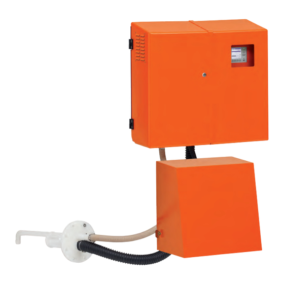
- Page 108 FWE200DH 7.2.3 Measuring and control unit Fig. 80: Measuring and control unit Ø 14 Designation Part No Measuring and control unit FWE200DH-NNJ 1066190 Measuring and control unit FWE200DH-NNE 1068441 Measuring and control unit FWE200DH-NNP 1069950 Measuring and control unit FWE200DH-BNJ...
- Page 109 FWE200DH Specifications Options 7.3.1 Remote unit Fig. 81: Remote unit Ø 8 Designation Part No Remote unit 2075567 Remote unit with integrated wide-range power pack 2075568 Endress+Hauser O P E R A T I N G I N S T R U C T I O N S...
- Page 110 Specifications FWE200DH 7.3.2 Frame Fig. 82: Frame (Measuring and control unit) (Blower unit) 1000 (Flange with tube) Ø 15 Designation Part No Frame 7047617 Endress+Hauser O P E R A T I N G I N S T R U C T I O N S...
- Page 111 Interface module, Ethernet type 1 2040965 7.3.6 Device check accessories Designation Part No Test equipment for linearity test FWE200DH 2072204 Endress+Hauser O P E R A T I N G I N S T R U C T I O N S 8029845/YWL2/V2-0/2016-10...
- Page 112 Specifications FWE200DH Consumable parts for 2-years operation 7.4.1 Measuring sensor Designation Number Part No Optics cloth 4003353 7.4.2 Blower unit Designation Number Part No Filter element, Europiclon 3000 l/min 5306090 Endress+Hauser O P E R A T I N G I N S T R U C T I O N S...
- Page 113 FWE200DH Annex Annex Standard settings FWE200DH The protocols for parameter settings when delivered (factory settings, see “Factory set- tings”, page 53) are part of the system documentation delivered with the measuring system and are therefore not described separately in these Operating Instructions.
- Page 114 8029845/YWL2/V2-0/2016-10 www.addresses.endress.com...
Need help?
Do you have a question about the FWE200DH and is the answer not in the manual?
Questions and answers