Advertisement
Quick Links
Advertisement

Summary of Contents for E-Tech DrivE-Tech 2.015
- Page 1 Installing and operating manual...
- Page 2 Index 1. DrivE-Tech Introduction ..............................3 2. Safety Instructions ................................3 3. Technical Characteristics ..............................4 3.1 Weight and dimensions ................................5 4. Electric wiring ..................................6 4.1 Protections ..................................... 12 4.2 Electromagnetic compliance ..............................12 4.3 Installation with long motor cables ............................12 5.
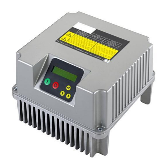
- Page 3 1. DrivE-Tech Introduction DrivE-Tech is a variable frequency drive designed to control and protect pumping systems by varying the output frequency to the pump. DrivE-Tech can be applied to both new and existing pumping systems, and provides: energy and cost savings ...
- Page 4 Max I in Max I out P2 motor Model Vin +/- 15% [V] Size power* [kW] 1 x Vin DrivE-Tech 2.015 1 x 230 3 x Vin 1 x Vin DrivE-Tech 2.030 1 x 230 3 x Vin DrivE-Tech 2.040...
- Page 5 3.1 Weight and dimensions Weight Size SIZE 1 SIZE 2 Model [Kg] DrivE-Tech 2.015 DrivE-Tech 2.030 DrivE-Tech 2.040 DrivE-Tech 2.055 DrivE-Tech 4.022 DrivE-Tech 4.040 DrivE-Tech 4.055 DrivE-Tech 4.075 DrivE-Tech 4.110 DrivE-Tech 4.150 SIZE 3 DrivE-Tech 4.185 DrivE-Tech 4.220 DrivE-Tech 4.300 DrivE-Tech 4.370...
- Page 6 4. Electric wiring Power board DrivE-Tech 2.015,2.030 Power supply: Output: 230 V AC auxiliary fans (wall LINE: L1, L2,GND 3 ph motor: mounting kit) It is recommended to use cable GND,U,V,W, FAN: F1, F2 lugs 1 ph motor: earth, U (running), V (common) It is recommended to use cable lugs.
- Page 7 Power board DrivE-Tech 2.040, 2.055 Power supply: Motor output: 12 V dc auxiliary fans (wall mounting kit) LINE: L1, L2, GND MOTOR: U, V, W, GND VENT: +, - It is recommended to use cable It is recommended to use cable WARNING: respect the polarity.
- Page 8 Power board DrivE-Tech 4.022,4.040 Power supply: Motor output: 12 V dc auxiliary fan (wall mounting kit) : LINE: GND , L1, L2, L3, MOTOR: U, V, W, GND 0VE, + VE It is recommended to use cable It is recommended to use cable WARNING: respect the polarity.
- Page 9 Power board DrivE-Tech 4.055,4.075,4.110,4.150 Power supply: Motor output: 12 V dc auxiliary fans (wall mounting kit) LINE: L1, L2, L3, GND MOTOR: U, V, W, GND VENT: +, - It is recommended to use cable It is recommended to use cable WARNING: respect the polarity.
- Page 10 Power board DrivE-Tech 4.185,4.220,4.300,4.370,4.450 P.E. MOTOR LINE Power supply: Motor output: LINE: L1, L2, L3, P.E. MOTOR: U, V, W, P.E. It is recommended to use It is recommended to use cable lugs. cable lugs. Cable stripping recommended for line input and output to the motor.
- Page 11 Control board Analog inputs (10 or 15 Vdc): Digital outputs: RS485 for COMBO: AN1: 4-20 mA: sensor 1 motor run signal: AN2: 4-20 mA: sensor 2 NO1, COM1: closed contact with motor running. AN3: 4-20 mA / 0 - 10 Vdc (settable ...
- Page 12 4.1 Protections The protections required upstream each DrivE-Techs depends on the type of installation, and local regulations. We recommend to use overload protection with the characteristic curve of type C and type B circuit breaker, sensitive to both AC and DC current. 4.2 Electromagnetic compliance To ensure electromagnetic compatibility (EMC) of the system, it is necessary to apply the following measures: ...
- Page 13 5. DrivE-Tech installation DrivE-Tech can be installed directly on the fan cover of the motor or mounted on the wall. Motor mounting kit In this application DrivE-Tech is cooled by the motor fan. Motor kit (available upon request) allows a solid coupling of the two units and it is composed of: DrivE-Tech SIZE 1 DrivE-Tech SIZE 2...
- Page 14 DrivE-Tech SIZE 3 n.° 1 motor feet adaptor for MEC160,180,200,225 n.° 4 M8 bolts, n.° 4 M10 bolts, nuts and washer...
- Page 15 Wall mounting kit In this application DrivE-Tech is cooled independently by its auxiliary cooling fan integrated in the radiator. Wall-mounted kit is composed of: DrivE-Tech SIZE 1 DrivE-Tech SIZE 2 n.° 1 auxiliary fan 230V AC (DrivE-Tech n.° 2 12 V DC fans. ...
- Page 16 5.1 DrivE-Tech Installation for constant pressure control DrivE-Tech controls the pump speed to maintain constant pressure at a set point independent of the water demand in the system. A basic schematic is shown below: 1: pump DrivE-Tech 2: check valve 3: pressure tank 4: valve 5: valve...
- Page 17 5.2 DrivE-Tech installation for differential constant pressure applications DrivE-Tech can manage the pump speed in order to keep constant the pressure difference between the dischage and suction side of the pump in circulation systems. To do this, it is usually installed a differential pressure sensor. Alternatively, it is possible to use two identical pressure sensors: one in suction side and one in discharge side of the pump.
- Page 18 6. DrivE-Tech Use and Programming DrivE-Tech software is extremely simple to use, but allows a wide variety of parameters to be set for ideal system calibration. Setting Parameters are organized in 2 levels: 1: Installer level (MENU’ CONTROL PARAMETERS, MENU’ IN/OUT PARAMETERS, MENU’ CONNECTIVITY PARAM.) A password is required for this level;...
- Page 19 Parameter Default Description End user communication language Language XXXX XXXXXX Unit Unit XXXXX Type of motor connected: Motor type single phase three-phase asynchronous three-phase XXXXXX synchronous PM (permanent magnets) Rated current of the motor per it’s nameplate indication increased Rated motor Amp.
- Page 20 If ON is selected, after a lack of voltage, DrivE-Tech returns to its Autorestart normal status; if DrivE-Tech was powering the pump before the voltage drop, it resumes powering the pump automatically. ON/OFF Warning, review the advice in chapter 1 Once the Setting procedure is completed you will get this indication INITIAL SETUP on the display;...
- Page 21 The calibration process can take up to one minute. Wait until it has completed. The calibration process must be performed during the final electrical configuration of the system, i.e. with the motor, the cable and any filter applied. If there is any variation of the motor, cable or filter applied, it is necessary to repeat the calibration process by accessing the motor parameters menu (default password 002).
- Page 22 6.3 Initial view When first powering the DrivE-Tech, the display shows : release of display software (LCD = X.XX) and the release of inverter software (INV = X.XX). The following End User messages are displayed by pushing the scroll buttons: p is the pressure value read by the pressure transducer.
- Page 23 6.4 Menu view Pressing ENTER when you are in [MENU’ / ENT to access] in initial display, will display the following MENUs: Installer password required to enter level 1 (default 001) MENU’ Control. param. Advanced password required to enter level 2 (default 002) MENU’...
- Page 24 Parameter Default Description Minimum value allowed in the system. If the readen value goes lower than this Min alarm value value, an alarm occurs and the pump is stopped. Pump is automatically restarted XXX.X [bar] if the readen value goes higher than the minimum value for a period of at least 5 seconds.
- Page 25 Parameter Default Description To ensure proper operation of pressure control is recommended to place the sensor near the pump. To compensate the pressure loss in the pipes (proportional to flow) it is possible to vary the pressure set in a linear relation with respect to frequency.
- Page 26 Parameter Default Description motor again; otherwise, DrivE-Tech will stop the pump. Delta control Value drop below the set value required to restart the pump during control ramp. XXX.X [bar] press. Set value Delta control Control ramp Stop delay Freq.min.control Min mot.
- Page 27 Parameter Default Description Address DrivE-Tech address: 00 master 01 to 07 slaves Function to allow alternating between the DrivE-Techs connected in COMBO (or pumps connected in DOL) in order to Alternance allow equal use of each pump in the group;...
- Page 28 6.6 Motor parameters Parameters Default Description Rated motor Volt. Motor rated voltage (as shown on motor nameplate). XXX [V] Voltage boost Voltage increase during the motor start up. Warning: An excessive value can seriously damage the motor. Contact the XX.X [%] motor manufacturer for further information.
- Page 29 Freq. PI Control Max motor freq. Ramp down time Ramp up time Stop delay Freq.min.control Control ramp Min. motor. freq. Ramp f min mot. Ramp f min mot. Sec. Carrier frequency (switching frequency). It is possible to choose PWM in the range of 2.5 ,4, 6, 8, 10 kHz . Higher values give a more sinusoidal wave with fewer losses for the motor but higher losses for the inverter (increased inverter heating).
- Page 30 If the device is "FOC-ready", motor calibration must be carried out MOTOR TUNING before commissioning. Carefully read the pertinent chapter. press ENT Manual setting of the stator resistance. Mot. resistance Rs=XXX.XX [Ohm] Manual setting of the stator inductance. Mot. inductance Ls=XXX.XX [mH] Setting of the control dynamic of the FOC algorithm.
- Page 31 Parameter Default Description AN1,AN2 function Function logic for analog input AN1,AN2 (independent, lower value, Independent higher value, difference 1-2). XXXXXX By selecting N.O. (normally open) DrivE-Tech runs the motor if the digital input 1 is open; motor will be stopped if the digital input 1 is closed.
- Page 32 7. Protections and alarms Anytime a protection occurs a blinking message is displayed together with an audible alarm; on STATUS in the initial view, the protection is displayed; by pressing the STOP button. Only from this position (STATUS) in the initial view is it possible to try to reset the alarm;...
- Page 33 Check possible causes reaching min value MIN. VALUE Measured value has reached the lowest (i.e. broken pipe, open pressure relief valve, etc.) ALARM value accepted by the system. Check the min alarm value setting. Increase the ramp-up time The current drawn by the load exceeds the ...
- Page 34 8. Auxiliary pumps during constant pressure control When the water needs vary considerably, it is advisable to share the water request between several pumps ensuring better efficiency and reliability. A first method consists of a single pump driven directly by DrivE-Tech and another 1 or 2 pumps directly connected to the mains DOL (Direct On Line);...
- Page 35 8.1 DOL pumps Each DOL pump is switched on by a contactor controlled by the digital output DOL1 and DOL2 present in the DrivE-Tech. DrivE-Tech relays driving the DOL pumps are relays with no voltage contacts. Max voltage to the contacts is 250 V, max current 5 A.
- Page 36 External switch Max 240 VAC, 5 A MANUAL Max 30 VDC, 5A Contactor AUTO Motor digital output 8.2 COMBO function In the “Control parameters” menu it is possible to enable the COMBO function that allows serial communication between up to 8 DrivE-Techs, each one connected to a pump. The operating principle (switch on/off) of pumps is similar to as stated in chapter 8.1.
- Page 37 Master setup 1. Supply power to the DrivE-Tech master. 2. If not yet completed, perform the initial configuration as described on chapter 6.2 3. Initial view is shown: Inv: ON/OFF Mot: ON/OFF p_mis=XX.X [bar] 4. Scroll until: Menù ENT to access 5.
- Page 38 Slave setup Follow Master setup until point 11. In case of failure of master in a Combo system, will be replaced by slave. As a consequence, all parameters must be setup independently on each inverter, master mode. 1. Set: DrivE-Tech’s address in parallel operation. Address ...
- Page 39 9. Trouble-shooting chart LCD does not switch on after powering Check the connecting flat cable between the LCD board (attached to the DrivE-Tech the cover) and the control board Check the fuses Check that the power cables are properly connected. ...
- Page 40 10. Technical Assistance For more technical information contact the authorized reseller providing the following information. The solution to the problem will be found faster and easier if full information is provided. Model/Serial Code LCD version (shown when DrivE-Tech is power INV version (shown when DrivE-Tech is supplied) power supplied)
- Page 41 DECLARATION OF CONFORMITY In according with: Machine Directive 2006/42/EC EMC Directive 2014/30/EU Low Voltage Directive 2014/35/EU R&TTE Directive 2014/53/EU DrivE-Tech is an electronic device to be connected to other electrical equipment with which it is to form individual units. It must, therefore, that the putting into service of this unit (with all its subsidiary equipments) to be performed by qualified personnel.
- Page 42 NOTE...
- Page 44 manDrivE-Tech_eng_31...
Need help?
Do you have a question about the DrivE-Tech 2.015 and is the answer not in the manual?
Questions and answers