
Subscribe to Our Youtube Channel
Related Manuals for Audiolab LIVE 48 PLUS


Summary of Contents for Audiolab LIVE 48 PLUS
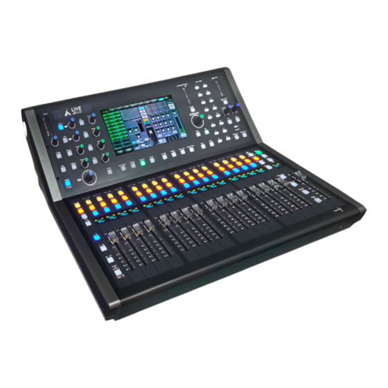
- Page 1 LIVE 48 PLUS DIGITAL MIXER WITH 48 CHANNELS USER MANUAL PLEASE READ THE INSTRUCTIONS CAREFULLY BEFORE USE P. 1 Versión Español | Tecshow NEBULA PAR 162 II...
- Page 2 Digital 4-band full parametric EQ DIGITAL MIXER WITH 48 CHANNELS • • Phase reverse LIVE 48 PLUS is a digital mixer with 32 line-level • Time delay inputs, 32 microphone preamplifers; Digital 4 band • 16 DCA for fader / mute group full parametric EQ;...
- Page 3 Impedances • Mic input: 6.8 kOhm • All output: 120 kOhm • Operating free-air temperature range: 0-40 ºC • Storage temperature range: -20-45 ºC Physical • Dimensions: XX • Weight: XX P. 3 English Version | AudioLab LIVE 48 PLUS...
- Page 4 The US Government’s instructions contained whithin the User’s Manual. Occupational Safety and Health Administration (OSHA) 10. To prevent fire and damage to the product, has specified the permissible exposure to noise level. P. 4 English Version | AudioLab LIVE 48 PLUS...
- Page 5 15. 17. OUTPUT PATCH Page 11: 18. SELECTED CHANNEL 22. LOAD Page 12: 23. TAP 32. USB PORT Page 13: 33. REC 45. MUTE BUTTON Page 14: 46. SELECT BUTTON 61. LCD DISPLAY P. 5 English Version | AudioLab LIVE 48 PLUS...
- Page 6 Class B digital device, technician for help. pursuant to Part 15 of the FCC Rules. These limits are designed to provide reasonable protection against P. 6 English Version | AudioLab LIVE 48 PLUS...
- Page 7 HPF or LPF button. Adjust Filter Type button to change the type. Adjust the button beside the HPF/LPF button to change the frequency needed. HPF/LPF FILTER HPF/LPF FILTER (THUMBNAIL) P. 7 English Version | AudioLab LIVE 48 PLUS...
- Page 8 Press the button to enter Assign page, signal from a control can be used to correct the reversed audio signal and cancel or enhance each other. selected input channel can be assigned to Main . P. 8 English Version | AudioLab LIVE 48 PLUS...
- Page 9 Press the button to switch the single channel / Multi channels which shows on LCD screen. MULTI CHANNELS SINGLE CHANNEL 13. SENDS Press the button to assign the selected channels to Bus 1-16, FX1 and FX2. SENDS P. 9 English Version | AudioLab LIVE 48 PLUS...
- Page 10 16 faders. After settings completed , touch User Layer button to enter custom mode /control. USER LAYER PAGE 17. OUTPUT PATCH The page is used to select output channel signal. OUTPUT PATCH P. 10 English Version | AudioLab LIVE 48 PLUS...
- Page 11 Please refer to the contents descriped in DSP control for more detailed operation. COPY 22. LOAD The page is used to load preset about scene, DSP ,GEQ and FX. LOAD P. 11 English Version | AudioLab LIVE 48 PLUS...
- Page 12 (notes: only can playback the files in MP3 that channel to the Solo bus and has no effect on the format.) Please refer DSP control chapter for detailed main. operation. P. 12 P. 12 English Version | AudioLab LIVE 48 PLUS English Version | NEO 371 3IN1...
- Page 13 Press this button will mute selected channel and all of be assigned. For the detail operation, please refer to its assigned outputs. It will illuminate when the introduction of DSP Control section. button has been pressed and enabled. P. 13 English Version | AudioLab LIVE 48 PLUS...
- Page 14 MIC . Mute other all inputs from the balanced channels It is used to diaplsy current information such as channel to ensure talkback function works normally. type, channel name , level value etc. ) P. 14 English Version | AudioLab LIVE 48 PLUS...
- Page 15 E) 2PCS or more DANTE linkage software need to be top panel. proceeded. 67. MAIN OUTPUT F) When Dante card inserted, it is needed to be set in This Digital Mixer features both XLR and TRS main switch mode. outputs. P. 15 English Version | AudioLab LIVE 48 PLUS...
- Page 16 B) Touch the tick in the box to select the parameter you want to copy. C) Press COPY button to make channel copy. Please notice the information displayed on LCD screen during your operation. P. 16 English Version | AudioLab LIVE 48 PLUS...
- Page 17 F) Touch it to set the amount of time for the gate to go from open to fully close. It can be set from 0.01 to 1 second. P. 17 English Version | AudioLab LIVE 48 PLUS...
- Page 18 3) Touch it in Polarity to invert the phase of the selected channel’s P. 18 English Version | AudioLab LIVE 48 PLUS...
- Page 19 It is used to let input signal enter output bus directly input signal source. Such as analog 1-32, digital 1-32. without passing through the processing of input signal such as fader, Mute,Gate,Comp, EQ control and so on. P. 19 English Version | AudioLab LIVE 48 PLUS...
- Page 20 D) Touch the icon to monitor selected channel audio signal, it will illuminate synchronized with Mute signal, it will illuminate synchronized with Solo button button on the panel. on the panel. P. 20 English Version | AudioLab LIVE 48 PLUS...
- Page 21 Please follow the instruction that is panel. J) Press this button to active RTA function. shown on the LCD display to adjust the value. K) The frequency and Gain value will be displayed here. P. 21 English Version | AudioLab LIVE 48 PLUS...
- Page 22 5.4 MIXER INTERFACE Press the mixer switch and then the following Mixer change synchronized. Once the channels on this Mixer page enable and corresponding BUS1 will enable interface will come to your eyes at first if you have preset. You can select CH01-CH48 channels or FX1-FX4 simultaneously.
- Page 23 5.6 MONITOR INTERFACE Touch the MONITOR icon to enter below interface: A) Touch the MONITOR icon to active/disable the monitoring function. There are total 8 groups (1-8) and you can use the knob on panel to select channel for each group from CH01- CH48 / BUS1-BUS16 / REV1-REV4 or Main channel.
- Page 24 D) Touch the icon to enter program setup page as below: 01-01 Audio device mode 48KHz and 96KHz as optional modes DANTE and NO CARD as two status, It shows DANTE if DANTE 01-02 Card Type card inserted. And shows NO CARD if none card inserted Meter Peak Inf --- Permanent.
- Page 25 F) Touch the icon to enter below setup interface: 03-01 Digital Signal Gain ENABLE 03-02 Fader Function Permission Setting Management limits: Grade1, Engineer mode Press System+1 to 03-03 Channel Mute/Monitor enter Grade 2, User mode Press System+2 to enter.Only can be used under the grade 1 engineer mode 03-04 Channel DSP...
- Page 26 H) Audio setup, Click and enter below interface There are two optional speed mode (FAST and SLOW ) for user to 06-01 FBC response speed adjust FBC response speed. 06-02 FBC response HIGH, LOW,MID as three options to release the speed. I) Touch USER KEYS box to enter below interface: There are 16 buttons which can be used as shortcut keys for different functions.
- Page 27 K) Fader grouping, click it to enter below interface: Click the corresponding numbered fader group button. Corresponding channel button flashes and enter registration preparation state, Select the channel and channel mute button which need to be setup. Click REGISTRATION to complete operartion. Up to 8 groups can be setup, After registration completed,if user move any fader in one group and then the whole group will change all together.
- Page 28 1) INPUT PATH: User can select different input sound 2) BUS MIX INPUT: Use it to let input signal to enter sources for each channel. And analog1-32 or digital ouput bus directly not via DSP process . It can proceed 1-32 can be used as input channels.
- Page 29 Click to enter Dante setup, Following the hookup diagrams to connect digital audio expansion system to mixer by network line. Click scan to search and all linked devices’ name can be shown in the list. Select the name of the digital signal receiving device: In below box user can select the device and channel which will be sent.
- Page 30 Click to enter below interface 1) INPUT PATH: Digital signal input. 2) BUS MIX INPUT: Digital signal output Select the needed channel and click on to open the Select the needed channel and click on to open the channel and adjust the gain of channel by selecting the channel and adjust the gain of channel by selecting the numbers on the channel.
- Page 31 7. HOOKUP DIAGRAM...
- Page 32 8. BLOCK DIAGRAM...
- Page 33 NOTES:...
- Page 34 a m p r o w e b . c o m /am progro up /am progro up /amprogro up /amprogro up...
Need help?
Do you have a question about the LIVE 48 PLUS and is the answer not in the manual?
Questions and answers