Advertisement
Quick Links
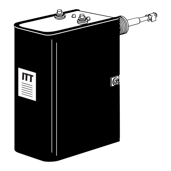
Series PSE-800
Probe Type Low Water Cut-Off
for Steam Boilers
U.S. Patents 7,161,492 & 7,436,187
Applications:
Residential and Commercial
• Before using this product read and understand instructions.
• Save these instructions for future reference.
• All work must be performed by qualified personnel trained in the proper application,
installation, and maintenance of plumbing, steam, and electrical equipment and/or systems
in accordance with all applicable codes and ordinances.
• To prevent flooding, do not use manual reset models with electric automatic water feeders.
• Boiler water pH levels above 10.0 may interfere with proper operation of the low water cut-off.
Levels above 10.0 must be corrected in order to ensure proper operation of the low water cut-off.
Failure to follow this warning may result in property damage, personal injury or death.
• To prevent electrical shock, turn off the electrical power before making electrical connections.
• This low water cut-off must be installed in series with all other limit and operating controls
installed on the boiler. After installation, check for proper operation of all of the limit and
operating controls, before leaving the site.
• We recommend that secondary (redundant) Low Water Cut-Off controls be installed on all
steam boilers with heat input greater than 400,000 BTU/hour or operating above 15 psi of
steam pressure. At least two controls should be connected in series with the burner control
circuit to provide safety redundancy protection should the boiler experience a low water
condition. Moreover, at each annual outage, the low water cut-offs should be dismantled,
inspected, cleaned, and checked for proper calibration and performance.
• When installing jumper wire make sure you are not introducing a second voltage source
into the burner circuit and thereby bypassing other safety, limit, and operating controls.
Failure to follow this warning could cause property damage, personal injury or death.
!
WARNING
McDonnell & Miller
Installation & Maintenance
Instructions
MM-284
Advertisement

Subscribe to Our Youtube Channel
Related Manuals for ITT McDonnell & Miller PSE-800 Series

Summary of Contents for ITT McDonnell & Miller PSE-800 Series
- Page 1 McDonnell & Miller Installation & Maintenance Instructions MM-284 Series PSE-800 Probe Type Low Water Cut-Off for Steam Boilers U.S. Patents 7,161,492 & 7,436,187 Applications: Residential and Commercial WARNING • Before using this product read and understand instructions. • Save these instructions for future reference. •...
- Page 2 Operation The Series PSE-800 probe type LWCO’s provide of the resistance readings. This new patented technology protection against low water conditions for residential provides the best protection possible without turning and commercial steam boiler applications. The control off the boiler unless a low water condition exists. As uses patented technology to monitor changes in an added measure of safety, the control will turn off water conductivity.
- Page 3 INSTALLATION TOOLS NEEDED: One (1) flathead screwdriver, and one (1) pipe wrench. For Remote Installations a level and power drill will be required. STEP 1 - Locating and Installing the Probe a. Based on the following criteria locate a suitable position for the probe: For all Applications: 1.
- Page 4 STEP 2 - Installing Control Box (continued) Direct Mounting b. Using a flathead screwdriver, loosen the probe mounting screws (F) 1/8" (3mm) about 1-1/2 turns and slip the control housing (G) over these two screws at a 20˚ angle. c. Rotate the control housing (G) 20˚ counter-clockwise so that the slots in the control base are firmly under the screw heads.
- Page 5 Remote Mounted Probe c. Connect the probe (A) to the wiring circuit by: Connecting a suitable 16 AWG wire (not provided) to the threaded end (V) of the probe (A). Place the lockwasher (K) and wing nut (L) (provided) over the threaded end of the probe and tighten the wing nut to 1/2 ft•lb (.65 N•m).
- Page 6 STEP 4 - Control Wiring (continued) d. For all wire connections to the terminal block (M). 1.Strip about 1/3" (8.5 mm) of insulation from the wire. 2.Loosen the terminal screw (N) but DO NOT REMOVE. Move the wire clamping plate (P) back until the plate touches the back side of the screw head.
- Page 7 STEP 5 - Testing Start-Up a. Before filling the system, turn on the electric power to the boiler. Set the thermostat to "heat". 1. Upon initial power up, the Green and Red lights will flash simultaneously 4 times. 2. The Green light will turn "ON". 3.
- Page 8 NOTE Clean probe by wiping with non-abrasive cloth and rinsing with clean water. DO NOT use sharp instruments to remove any accumulations of rust or scale. ©2009 ITT Corporation Printed in U.S.A. 4-09 211630 8200 N. Austin Ave. Morton Grove, IL 60053...
Need help?
Do you have a question about the McDonnell & Miller PSE-800 Series and is the answer not in the manual?
Questions and answers