Advertisement
Advertisement
Table of Contents

Summary of Contents for M3 HVM Series
- Page 1 HVM Series High Voltage Switch Matrix User’s Manual...
-
Page 2: Safety Precautions
Safety Precautions The following safety precautions should be observed before using this product and any associated instrumentation. The WARNING heading in a manual explains dangers that might result in personal injury or death. Always read the associated information very carefully before performing the indicated procedure. The CAUTION heading in a manual explains hazards that could damage the instrument. -
Page 3: Installation
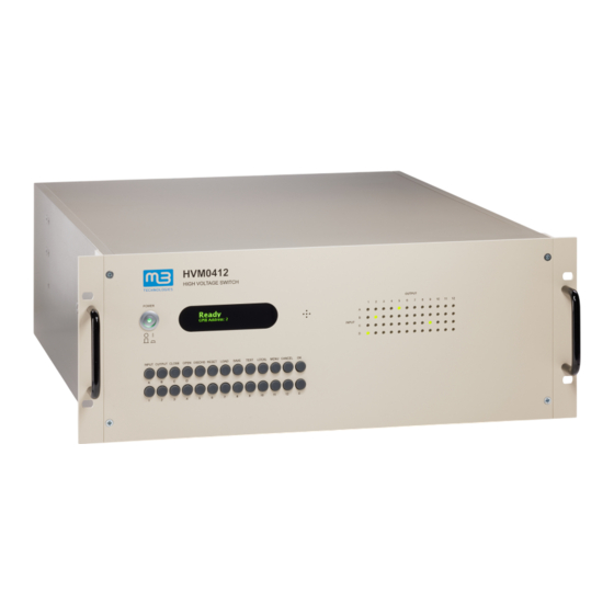
Introduction The mb-Technologies HVM high voltage switch series is a computer-controlled switching matrix designed for semiconductor characterization applications. It connects a number of instruments - connected to the matrix inputs - to test structures connected to the matrix outputs. The connection is done using a high voltage relay matrix with guarded contacts. Optionally, triple-switch FORCE, SENSE and GUARD relays are used at each switch point to support low-leakage Kelvin measurements. -
Page 4: Communication Setup
WARNING: When installing this equipment in places where access to the main power cord is restricted, such as rack mounting, a separate main input power disconnect device must be provided, in close proximity to the equipment and within easy reach of the operator. WARNING: Chassis connections must only be used as shield connections for measuring circuits, NOT as safety earth ground connections. -
Page 5: Display And Keyboard
This installation only needs to be done once. The port automatically becomes available each time the switch is connected and turned on. LAN Setup: Connect the switch to your local network and turn it on. Press SETUP, select 1 (SETUP), 3 (LAN) and press OK. -
Page 6: Backside Panel
POWER: Used to turn the unit on or off. Please also note the power switch on the backside panel. INPUT, OUTPUT Used to select relays. CLOSE, OPEN Turns the selected relays on or off. DISCHG Toggles the discharge relays. RESET Opens all relays. -
Page 7: Maintenance
WARNING: Do not try to use non-matching connectors or wires. WARNING: The maximum voltage rating for each connector is labeled on the backside panel. Do not apply any higher voltage. This also applies to connections through the matrix. The right side of the backside panel has USB, LAN, RS232 and GPIB communication interfaces, a digital I/O connector, a ground connector stub and the main power jack connector with integrated switch and fuses installed. - Page 8 Input/Output #13 General input or output Input/Output #14 General input or output Input/Output #15 General input or output Input/Output #16 General input or output BUSY (Output) HIGH when the switch is executing a command, LOW when idle. WAIT (Input) When pulled HIGH the switch suspends execution.
- Page 9 Relay numbers Relays are specified by a letter defining the matrix input (A to L) followed by a number defining the matrix output (1 to 12). Alternatively a relay can be specified by a 5 digit number biioo, where b=board (always 1), ii=input and oo=output.
- Page 10 Example: Response: *TST *OPC? *TST? 2 (A2,B4) *REM Set device to remote mode which disables the keyboard. *LOC Set device to remote mode which enabled the keyboard. [:][ROUTe:]CLOSe[:LIST] relay_list Closes the relays specified in the list. relay_list: List of relay numbers. Example: CLOSE A1,B3,H6 :ROUT:CLOS:LIST (@10101,10102,10201,10202)
- Page 11 Response for each relay (delimited by ','): Relay is opened Relay is close Example: Response: OPEN ALL CLOSE A1,B2 :ROUT:OPEN:LIST? (@A1,B1,B2,B3) 0,1,0,1 [:][ROUTe:]DIScharge? Read the logic level of the DISCHARGE line. Response: 0 or 1 0=NORMAL, 1=DISCHARGE [:][ROUTe:]DIScharge value Activates DISCHARGE or - if not activated by the external signal - disabled it. Note DISCHARGE cannot be deactivated by software if the external signal on the digital I/O connector (pin 19) activated.
- Page 12 [:][ROUTe:]CONNection: SEQuence? Queries the connection sequence. Response: NSEQ No sequence Break before make MBBR Make before break [:]DIGital:[DEFine:]INPput line Defines a digital I/O line to work as input. line: 1 to 16 [:]DIGital:[DEFine:]OUTput line Defines a digital I/O line to work as output. line: 1 to 16 [:]DIGital:[DEFine:]INPut:Byte byte...
- Page 13 [:]DIGital:Word? Read the logic level of all 16 digital I/O lines. Response: 0 to 65535 Binary coded value [:]DIGital line, level Sets the logic output level of a digital I/O line. line: 1 to 16 level: 0 or 1 0=LOW, 1=HIGH [:]DIGital:Byte byte, value Sets the logic output level of 8 digital I/O lines.
- Page 14 10211 127 902 [:]SYStem:Board:Serial? board Returns the PCB serial numbers and fabrication dates of the installed electronics boards. board: 1 to 12 Relay board Logic board Power board Display board Backplane board Response: serial, date Example: SYSTEM:BOARD:SERIAL? 101 Result: DEABCCE3,20161217 Remarks: The serial numbers are returned as 32 bit hex numbers, the fabrication data in YYYYMMDD format.
-
Page 15: Specifications
Specifications Parameter Value Conditions Isolation Voltage 3000V Between any unconnected input or output and any other input or output or ground. Isolation Voltage between 500V Force and Sense (if available) are usually connected. Guard is Force and Guard or assumed to be driven at the same voltage. Sense and Guard of the same input or output Carry Current... - Page 16 Contact For any questions please contact: mb-Technologies GmbH Dreikreuzweg 8 8280 Fuerstenfeld Austria +43 664 73522586 office@mb-technologies.com UM_HVM_20231015E...
Need help?
Do you have a question about the HVM Series and is the answer not in the manual?
Questions and answers