
Summary of Contents for FRAMOS HPSC Series
- Page 1 User Manual LED Strobe Controller Family IPSC1 IPSC2 IPSC4 HPSC1 HPSC1 v2 HPSC2 HPSC4...
- Page 2 For purpose of this User Manual affiliates are: FRAMOS Technologies d.o.o., FRAMOS Technologies Inc, FRAMOS Italia, FRAMOS Electronics Ltd, and MAVIS Imaging GmbH (hereinafter all together: FRAMOS) ©...
-
Page 3: Technical Support
Customers, Integrators and End Users using or selling these products for use in such applications do so at their own risk and agree to fully indemnify FRAMOS for any damages resulting from any improper use or sale. www.framos.com Version v2.3.0 from 2023... -
Page 4: Table Of Contents
IPSC4 ............................21 3.3.1. Dimensions ........................22 3.4. Physical Interfaces ........................23 3.4.1. Power Input ........................23 3.4.2. Output Connector ......................24 3.4.3. Trigger Input ........................26 Version v2.3.0 from 2023 © FRAMOS 2023, information is subject to change without prior notice... - Page 5 Trigger Input Parameters ....................48 7.9. Lightheads (IPSC-series only) ....................50 7.9.1. Digital EEPROM Lighthead Signature ................50 7.10. Firmware Update ........................55 7.11. Other features ......................... 57 Version v2.3.0 from 2023 © FRAMOS 2023, information is subject to change without prior notice...
- Page 6 Description Tab ....................... 57 7.11.2. Log Tab ..........................57 7.11.3. Status Tab ........................57 Web Server ............................59 Revision History ..........................60 Contact Information ........................61 Version v2.3.0 from 2023 © FRAMOS 2023, information is subject to change without prior notice...
-
Page 7: Overview
FRAMOS is committed to complying with this Directive and has worked in collaboration with its suppliers to evaluate the new restrictions, to identify relevant exemptions, and to substitute environmentally benign, compliant alternative materials in its product components and manufacturing processes. - Page 8 FRAMOS is committed to complying with the WEEE Directive (as implemented in each EU member state). In accordance with the requirements of the Directive, FRAMOS Technologies d.o.o.
-
Page 9: Precautions
LED illumination should never be connected or disconnected to the strobe controller when the power output is enabled. Always turn the device off when changing LED illumination. Version v2.3.0 from 2023 © FRAMOS 2023, information is subject to change without prior notice... -
Page 10: Cabling Recommendation
(H / W / L) [mm] Weight (approx.) 285g 715g 270g 285g 297g 635g Table 1: Family models *for HPSC1 v2, HPSC2 and HPSC4 on request Version v2.3.0 from 2023 © FRAMOS 2023, information is subject to change without prior notice... -
Page 11: Hpsc-Series
From -5°C/+23°F up to +50°C/+122°F (ambient) Relative humidity From 25% up to 80% (non-condensing) Table 2: HPSC1, HPSC1 v2, HPSC2 and HPSC4 - Mechanical and electrical specifications Version v2.3.0 from 2023 © FRAMOS 2023, information is subject to change without prior notice... -
Page 12: Value Ranges And Precision
In External Trigger, these times are bigger. Version v2.3.0 from 2023 © FRAMOS 2023, information is subject to change without prior notice... - Page 13 HPSC4 Range2 Minimal Delay Time (7000mA down to 701mA) Range3 (40A down to 7001mA) Table 4: Minimum delay time for HPSC1 v2, HPSC2 and HPSC4 Version v2.3.0 from 2023 © FRAMOS 2023, information is subject to change without prior notice...
-
Page 14: Physical Interfaces
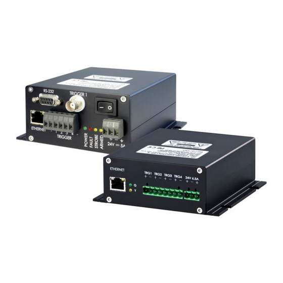
The Power Input connector, as shown in Figure 1, is located near the lower right corner of the HPSC front panel. All devices require an external 12V – 24V DC supply for operation (specified in chapter 2.1 - Mechanical and Electrical Specifications). Version v2.3.0 from 2023 © FRAMOS 2023, information is subject to change without prior notice... -
Page 15: Trigger Inputs
Table 6: Trigger input connector description HPSC-Series The electrical ratings, operation limits as well as the device internal circuitry are described in Table 7 and Figure 2 below. Version v2.3.0 from 2023 © FRAMOS 2023, information is subject to change without prior notice... - Page 16 The current draw for each input line is 6 to 10 mA. Table 7: HPSC-Series - Electrical Specification - Trigger Input(s) Figure 2: Internal input trigger scheme for HPSC-Series Version v2.3.0 from 2023 © FRAMOS 2023, information is subject to change without prior notice...
-
Page 17: Led Output
LED+ LED Power Output n + (common for all channels) LED - LED Power Output n - Table 8: Illumination Output (LED) connector description HPSC-Series Version v2.3.0 from 2023 © FRAMOS 2023, information is subject to change without prior notice... -
Page 18: Trigger Output
Table 10: HPSC-Series – Trigger Output (OUT) maximum ratings H PSC1 HPSC1 OUT + OUT + BC847C SMCJ24A BC847C SMCJ24A OUT - OUT - Figure 4: HPSC1 – Trigger Output (OUT) – Schematics Version v2.3.0 from 2023 © FRAMOS 2023, information is subject to change without prior notice... -
Page 19: Mechanical Drawings
Figure 5: HPSC1 v2, HPSC2, HPSC4 – Trigger Output (OUT) – Schematics 2.4. Mechanical Drawings 2.4.1. Dimensions of HPSC1 74,60 4,20 16,50 Figure 6: Dimensions of HPSC1 in mm Version v2.3.0 from 2023 © FRAMOS 2023, information is subject to change without prior notice... -
Page 20: Dimensions Of Hpsc1 V2
User Manual LED Strobe Controller Family 2.4.2. Dimensions of HPSC1 v2 Figure 7: Dimensions of HPSC1 v2 in mm Version v2.3.0 from 2023 © FRAMOS 2023, information is subject to change without prior notice... -
Page 21: Dimensions Of Hpsc2
User Manual LED Strobe Controller Family 2.4.3. Dimensions of HPSC2 Figure 8: Dimensions of HPSC2 in mm Version v2.3.0 from 2023 © FRAMOS 2023, information is subject to change without prior notice... -
Page 22: Dimensions Of Hpsc4
User Manual LED Strobe Controller Family 2.4.4. Dimensions of HPSC4 6,40 Figure 9: Dimensions of HPSC4 in mm Version v2.3.0 from 2023 © FRAMOS 2023, information is subject to change without prior notice... -
Page 23: Ipsc-Series
Black aluminum case External dimensions 39 x 88 x 103 mm (H / W / L) Weight approx. 285g Storage temperature (ambient) from -30°C/-22°F up to +80°C/+176°F Version v2.3.0 from 2023 © FRAMOS 2023, information is subject to change without prior notice... -
Page 24: Dimensions
LED Strobe Controller Family Operating temperature (ambient) from -5°C/+23°F up to +50°C/+122°F Table 11: IPSC1 - Specification 3.1.1. Dimensions Figure 11: Dimensions of IPSC1 in mm and [inch] Version v2.3.0 from 2023 © FRAMOS 2023, information is subject to change without prior notice... -
Page 25: Ipsc2
(H / W / L) Weight approx. 285g Storage temperature (ambient) from -30°C/-22°F up to +80°C/+176°F Operating temperature (ambient) from -5°C/+23°F up to +50°C/+122°F Table 12: IPSC2 - Specification Version v2.3.0 from 2023 © FRAMOS 2023, information is subject to change without prior notice... -
Page 26: Dimensions
User Manual LED Strobe Controller Family 3.2.1. Dimensions Figure 13: Dimensions of IPSC2 in mm and [inch] Version v2.3.0 from 2023 © FRAMOS 2023, information is subject to change without prior notice... -
Page 27: Ipsc4
(H / W / L) Weight approx. 680g Storage temperature (ambient) from -30°C/-22°F up to +80°C/+176°F Operating temperature (ambient) from -5°C/+23°F up to +50°C/+122°F Table 13: IPSC4 - Specification Version v2.3.0 from 2023 © FRAMOS 2023, information is subject to change without prior notice... -
Page 28: Dimensions
User Manual LED Strobe Controller Family 3.3.1. Dimensions Figure 15: Dimensions of IPSC4 in mm and [inch] Version v2.3.0 from 2023 © FRAMOS 2023, information is subject to change without prior notice... -
Page 29: Physical Interfaces
12V – 24V DC supply for operation, specified in Chapter 3. Description Phoenix Contact MSTB 2,5/ 3-ST-5,08 Type Power Supply (+12 to 24V DC) Power GND Protective Earth Table 14: Power connector description IPSC-Series Version v2.3.0 from 2023 © FRAMOS 2023, information is subject to change without prior notice... -
Page 30: Output Connector
12V – 24V (depends on power supply) DC, max 0.5A (for light head cooling fan) Power GND V+, Common Output Voltage Table 15: Output connector description IPSC-Series Version v2.3.0 from 2023 © FRAMOS 2023, information is subject to change without prior notice... - Page 31 User Manual LED Strobe Controller Family Figure 17: Connecting scheme for LED output Figure 18: IPSC-Series - Trigger Output – Schematics Version v2.3.0 from 2023 © FRAMOS 2023, information is subject to change without prior notice...
-
Page 32: Trigger Input
+3V to +24V DC LOW / Logical 0 0 to +0.5V DC Undefined State +0.5V to +3V DC Table 17: Electrical Specification - Trigger Input(s) Version v2.3.0 from 2023 © FRAMOS 2023, information is subject to change without prior notice... - Page 33 24V voltage. The shown pull down 1.2kΩ resistor should be rated for at least 0.5W power. Figure 20: Trigger circuit example from Opto-Isolated source Version v2.3.0 from 2023 © FRAMOS 2023, information is subject to change without prior notice...
-
Page 34: Interfaces For Configuration
The assignment of the connector on the strobe controller can be found below. IPSC HPSC 4 →6, 7→8 Handshaking loop back 1, 9 Not connected Version v2.3.0 from 2023 © FRAMOS 2023, information is subject to change without prior notice... - Page 35 User Manual LED Strobe Controller Family Table 20: RS-232 connector assignment Note: The IPSCs and HPSCs series can be connected using a straight-through cable. Version v2.3.0 from 2023 © FRAMOS 2023, information is subject to change without prior notice...
-
Page 36: Status Leds
Other Running Modes: Indicates trigger, flashing rate is limited to Flashing (max. 17Hz) max. 17 Hz Table 22: HPSC1 v2, HPSC2 and HPSC4 - Status LEDs and description Version v2.3.0 from 2023 © FRAMOS 2023, information is subject to change without prior notice... -
Page 37: Ipsc-Series
The Ethernet connector provides a yellow and a green LEDs, where the green LED indicates link, the yellow one activity. Green LED (left) Status No link Solid on Link on / Ethernet link exists Version v2.3.0 from 2023 © FRAMOS 2023, information is subject to change without prior notice... -
Page 38: Error / Fault Codes
Check parameters on controller so they are not overloading controller and light head Check that light head is connected properly Send new parameters to controller Please contact your local Framos distribution partner if the error code persists. Version v2.3.0 from 2023 © FRAMOS 2023, information is subject to change without prior notice... -
Page 39: Getting Started
Assembled cables are available as accessory from our sales partners. o HPSC-Series: Flying leads can be directly attached to the devices screw terminal, Version v2.3.0 from 2023 © FRAMOS 2023, information is subject to change without prior notice... -
Page 40: Software Installation - Smartek Vision Sclib
10Mbit Ethernet network card (or faster), RS232 interface or USB1.x/2.0 interface o SMARTEK Vision ScLib PC configuration software, optional web browser software. 6.2. Software Installation – SMARTEK Vision ScLib Please contact your local sales representative for the latest version of the Framos Strobe Step 1: controller software. - Page 41 ScLibClient or web-interface. Select the right Running Mode for your application and configure the Trigger Inputs as well as the Physical Outputs according to your requirements. Version v2.3.0 from 2023 © FRAMOS 2023, information is subject to change without prior notice...
- Page 42 Send & Save which applies and stores the settings to the strobe controller. Further information on the configuration interface can be found in the following Chapter 7 - Device Configuration with the ScLibClient. Version v2.3.0 from 2023 © FRAMOS 2023, information is subject to change without prior notice...
-
Page 43: Device Configuration With The Sclibclient
The ScLibClient is a graphical user interface application for strobe controller discovery, configuration and status. It is part of the ScLib which is a collection of software tools, programming samples and documentation to configure, run and integrate devices into user applications. All Framos Strobe Controllers, specified in this document, are supported. -
Page 44: Find Devices
Find Controllers window is to select Broadcast and make sure to check the relevant interfaces. Figure 25: ScLibClient – Discovery Window Version v2.3.0 from 2023 © FRAMOS 2023, information is subject to change without prior notice... -
Page 45: Ethernet Specific Discovery Options
Depending on the type of connection that is used towards the strobe controller, the results of a search might be different. Figure 28 shows how correct detected devices with a valid IP address are listed. Version v2.3.0 from 2023 © FRAMOS 2023, information is subject to change without prior notice... - Page 46 Make sure to provide an IP address to the controller that is not assigned to another device in the network. Version v2.3.0 from 2023 © FRAMOS 2023, information is subject to change without prior notice...
- Page 47 IP and connected only if the gateway is correctly set. Gateway and DNS are currently only implemented on HPSC1 v2, HPSC2 and HPSC4 devices. Version v2.3.0 from 2023 © FRAMOS 2023, information is subject to change without prior notice...
-
Page 48: Strobe Controller Status
Send button. These values are stored to volatile memory and will be dropped on power cycle or reset of the device. Version v2.3.0 from 2023 © FRAMOS 2023, information is subject to change without prior notice... -
Page 49: Running Modes
The trigger signals are only processed sequentially and thus it is not possible to operate several channels asynchronously to each other. For asynchronous application, please use on of our HPSC devices. Version v2.3.0 from 2023 © FRAMOS 2023, information is subject to change without prior notice... -
Page 50: Off
The signal is defined by the configured On-Time, Off-Time and Delay-Time. In this mode any external or software triggers are ignored. Version v2.3.0 from 2023 © FRAMOS 2023, information is subject to change without prior notice... -
Page 51: Output Parameters
• Trigger – Trigger which will be used to drive the output line(s) • Measured Current / Voltage – Actual measured voltage and current at the output lines Version v2.3.0 from 2023 © FRAMOS 2023, information is subject to change without prior notice... -
Page 52: Optimal Autosense
Exchanging the illumination (even with the same light head type) can show differences in brightness. This is caused by normal tolerances in manufacturing that might make slightly higher voltages necessary to reach the specified current. Version v2.3.0 from 2023 © FRAMOS 2023, information is subject to change without prior notice... -
Page 53: Controller Settings
• Max. Temperature – Maximum Temperature before the device goes into safe shutdown, used to limit the maximum temperature for heat sensitive environments e.g. in medical applications. Version v2.3.0 from 2023 © FRAMOS 2023, information is subject to change without prior notice... -
Page 54: Trigger Input
• On Time – definition of the pulse length. Please be careful with this parameter, too high values of On Time can damage the light heads. Version v2.3.0 from 2023 © FRAMOS 2023, information is subject to change without prior notice... - Page 55 Figure 36 below shows how the timing of each trigger input line is transferred to the corresponding output(s). Figure 36: Process of generating pulses Version v2.3.0 from 2023 © FRAMOS 2023, information is subject to change without prior notice...
-
Page 56: Lightheads (Ipsc-Series Only)
Digital light head signature of the lighting device is accessed by pressing the F4 key on keyboard. In the Digital Lighthead Signature window, additional information is provided about strobe controller and light head. Version v2.3.0 from 2023 © FRAMOS 2023, information is subject to change without prior notice... - Page 57 EEPROM with current parameters click on Write EEPROM (3) button. To see current parameters in raw hex format, go to Raw EEPROM Signature Data (4) tab. Version v2.3.0 from 2023 © FRAMOS 2023, information is subject to change without prior notice...
- Page 58 • Max Pulsed Current – maximal allowable current trough LED when the device is in pulse mode, with a value between 1 – 65535 [mA] Version v2.3.0 from 2023 © FRAMOS 2023, information is subject to change without prior notice...
- Page 59 Figure 42: ScLibClient – Status Tab ID Check Mode – gives information for ID Check Mode setting: • 0 – IPSC does not perform any checking Version v2.3.0 from 2023 © FRAMOS 2023, information is subject to change without prior notice...
- Page 60 128 ± 8 – Light head is not connected • 97 ± 8 – Light head is connected • 68 ± 8 – AID output is connected to GND Version v2.3.0 from 2023 © FRAMOS 2023, information is subject to change without prior notice...
-
Page 61: Firmware Update
4) After selecting a firmware, click on the Check firmware file button to run a compatibility test between the device and firmware. Figure 46: Firmware update (3) Version v2.3.0 from 2023 © FRAMOS 2023, information is subject to change without prior notice... - Page 62 Depending on the device, this process can take a couple of minutes. When updating of new firmware finishes, simply close the dialog box. Figure 48: Firmware update (5) Version v2.3.0 from 2023 © FRAMOS 2023, information is subject to change without prior notice...
-
Page 63: Other Features
Status Tab The current status information of the selected Strobe Controller can be viewed by selecting the Status tab. Figure 51: Additional features – Status tab Version v2.3.0 from 2023 © FRAMOS 2023, information is subject to change without prior notice... - Page 64 Firmware Versions. In the table below, you can see some controller specific information. Controller Specific Information IPSCx ID Check Mode, Analog ID HPSC1 v2, HPSC2, HPSC4 FSBL Version, Format Version Table 28: Controller information Version v2.3.0 from 2023 © FRAMOS 2023, information is subject to change without prior notice...
-
Page 65: Web Server
To gain access, just enter IP address (1) of the target device into your web browser. Use the web server to read and send parameters to the device (2), or to change its IP address (3). Figure 52: IPSC devices web interface Version v2.3.0 from 2023 © FRAMOS 2023, information is subject to change without prior notice... -
Page 66: Revision History
Initial Framos brand release v2.2.1 2018-04-13 Corrected dimensions for IPSC4, HPSC4, descriptions updates, minor fixes v2.2.0 2018-01-18 Added specifications for HPSC1 v2 and HPSC2 v2.1.1 2017-04-28 Initial release Version v2.3.0 from 2023 © FRAMOS 2023, information is subject to change without prior notice... -
Page 67: Contact Information
FRAMOS IP. More than 180 FRAMOS employees world-wide are passionate about the unlimited potential of imaging and help customers achieve the optimum results from every possible scenario. FRAMOS drives and ensures the entire product development journey from POC, through prototyping, to mass production. - Page 68 WWW.FRAMOS.COM Version v2.3.0 from 2023 © FRAMOS 2023, information is subject to change without prior notice...
Need help?
Do you have a question about the HPSC Series and is the answer not in the manual?
Questions and answers