Advertisement
Quick Links
INSTALLATION & OPERATION
MANUAL
All-In-One Type Air Source Heat Pump Water Heater
Model: HPWSTR002 / HPWSTR003
Soltaro_ASHP_Manual V1.3
Thank you for purchasing our product,
please keep this installation
manual carefully and read this
manual carefully before you install
the heat pump.
Advertisement

Summary of Contents for Soltaro HPWSTR002
- Page 1 INSTALLATION & OPERATION MANUAL All-In-One Type Air Source Heat Pump Water Heater Model: HPWSTR002 / HPWSTR003 Soltaro_ASHP_Manual V1.3 Thank you for purchasing our product, please keep this installation manual carefully and read this manual carefully before you install the heat pump.
- Page 2 NOTES Dear customers, Thank you for selecting our products. The manual aims to provide instructions for the installation, operation and maintenance of heat pump, providing important safety information. Please carefully read the entire contents of this manual before you install and use heat pump.
- Page 3 SAFETY PRECAUTIONS Please make sure you have read at least one chapter of safety precautions shown in the manual. This part provides important safe points for you. Please operate it based on safety precautions. WARNING 1.Household electrical system must have a reliable ground connection; 2.
- Page 4 Class III conditions; All-pole disconnect switch), then the disconnect device must be incorporated into the fixed wiring according to the arrangement of wiring rules; 17. The minimum installation room area for HPWSTR002 is 69 square meters, and the minimum installation room area for HPWSTR003 is 42 square meters, unless the products are used entirely outside;...
- Page 5 30. This appliance is not intended for use by persons (including children) with reduced physical, sensory or mental capabilities or lack of experience and knowledge unless they have been given supervision or instruction concerning use of the appliance by a person responsible for their safety. 31.
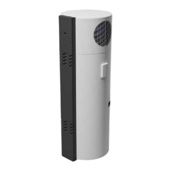
- Page 6 GENERAL INFORMATION I. Measurement Model Weight(kg) Dimension(mm, Power supply Water connection size D×H) HPWSTR002 φ620mm*1518mm 220V/ 50Hz/ 1 phase 3/4” HPWSTR003 φ620mm*1838mm 220V/ 50Hz/ 1 phase 3/4” II. External appearance...
- Page 7 III. Features All in one heat pump for sanitary hot water: 1. Has complete isolation between water and electricity, without electric shock possibilities; 2. No fuel tubes and storage, no potential danger from oil leakage, fire, explosion, etc.; 3. No cross-contamination potential, the condenser coil is an external coil wrapped around the stainless tank, it does not come in contact with water directly;...
- Page 8 IV.Refrigerant circuit Compressor: R290, supplied by GMCC. Evaporator: Copper tube and aluminum fin type heat ex-changer. EXV: Electronic expansion valve, the opening is regulated according to the discharge air temperature of compressor. Fan: Centrifugal fan with three speeds. High Pressure Switch: When the discharge pressure of compressor is 2.76Mpa or higher, protection switch will be triggered, then if the discharge pressure is below 2.07MPa, the protection switch will disengage.
- Page 9 V.Specifications Model HPWSTR002 HPWSTR003 Power supply 220V~240V/50HZ 220V~240V/50HZ Rated Input Power(Heat pump) 1.2KW 1.2KW Rated Input Current(Heat pump) 5.3A 5.3A Rated Heating Capacity(Heat pump) 2.78KW 2.78KW Rated Input Power(Resistance) 1.8KW 1.8KW Rated Input Current(Resistance) 7.5A 7.5A Max Current(HP&Resistance) Water tank volume...
- Page 10 PART NAMES NOTE All the pictures in this manual are for explanation purposes only. They may be slightly different from the heat pump water heater you purchased (depending on the model). Please refer to the real sample instead of the pictures of this manual. INSTALLATION OF HEAT PUMP Choose a suitable location Avoid installing this equipment indoors.
- Page 11 Ensure sufficient space for installation and maintenance; Inlet or outlet air must have no obstacles and be sheltered from strong winds; Dry and ventilated place is most suitable; Support surface must be flat (horizontal angle must not be more than 2°C), and able to bear heat pump’s weight.
- Page 12 II. MOVEMENT OF HEAT PUMP This heat pump is heavy requires at least two people to move and install it; Please move the equipment according to the original factory packaging; Please use protection during transit to avoid scratches and damage to the unit; Do not touch fan with your hands or other objects;...
- Page 13 III. INSTALLATION OF HEAT PUMP Please leave enough space for installation and maintenance. If heat pump is installed in the basement, indoors or other airtight space, please note exhaust and intake circulation between surrounding air and outdoor air; If ducting is used, the air duct total length should be equal to or less than 6 meters, and the duct diameter should be equal to or more than 150 mm.
- Page 14 IV. EXTERNAL PRODUCT DIMENSIONS Size Model HPWSTR002 1518 1010 HPWSTR003 1838 1330...
- Page 15 PIPE LINE CONNECTION I. PIPE CONNECTION DIAGRAM II. WATER QUALITY REQUIREMENTS PH value Total Conductivity Sulphate ion Chlorine Ammonia hardness 7~8.5 < 50ppm <200μV/cm None < 50ppm None (25℃) Sulfate ion Silicon Iron content Sodium < 50ppm < 50ppm < 0.3ppm <...
- Page 16 III. WATER PIPE INSTALLATION INSTRUCTIONS Do not use iron pipe for heat pump connections. CPVC pipe, PPR pipe or PB pipe or other pipe as per local regulations is recommended; Water pipes, connectors etc., must be installed according to the drawing. If the ambient temperature is below 0 ℃, proper insulation must be installed for the water pipes;...
- Page 17 After pipe installation is complete, open up the valve controlled cold water inlet and the valve controlled hot water outlet to fill water into tank, you can stop when water overflows from water outlet, then inspect all piping and ensure there is no water leakage.
- Page 18 NOTE The equipment must be connected to the correct power supply, supply voltage must comply with rated voltage; Power supply circuit must be fitted with a grounding wire, and grounding wire of power supply must be reliably connected with external grounding wire; The installation must be undertaken by professional personnel based on provided circuit diagrams;...
- Page 19 (mm2) Model device Size (continuous Ground Capacity Fuse Rated current length ≤ wire 30m) HPWSTR002 Below 30mA 220V/50Hz HPWSTR003 0.1sec ≥20 ≥20A ≥2.5 ≥Φ1.0mm Remark: Ple ase directly connect power supply wire with user’s plug when using the heat pump.
- Page 20 3. INTERNAL WIRING DIAGRAM...
- Page 21 METHOD OF APPLICATION When using the unit, please operate in the following order Feeding water: when using the unit for the first time (or reusing it after the tank is emptied), before connecting the unit to power, please make sure the tank is full of water.
- Page 22 Water draining: before cleaning or moving the unit, please drain the water in the water heater. The draining method is as per below picture: INSTRUCTION OF OPERATION 1. CONTROL SYSTEM SPECIFICATIONS (1) Operating condition Voltage:220V~±10%,50Hz±1Hz. Ambient temperature: -7~+43°C Storage temperature: -20~+75°C Relative humidity: 0~95%RH Temperature accuracy: ±1°C (2) Main Function...
- Page 23 Forced defrost. Large LCD display. Protection functions. The error code display and query Key-Lock Function Anti-freezing function When there is no wired controller or wired controller is broken, the system will recognize it, and control the heat pump to run automatically. 2.
- Page 24 4. During clock setting, press the key and fold for 3s, enable or disable the week function 1. Press the key and hold for 5s, enter into parameter setting interface Mode key 2. Press the key to change operation mode 3.
- Page 25 2) Instruction of the buttons Status Symbol Meaning Heat pump OFF or not in heating Not bright mode Light up In heating mode Light up Heating element ON Flash for 1s Run in Boost mode Flash for 2s Run in sterilization mode Light up Water temperature Light up...
- Page 26 Light up Degree centigrade Light up Degree Fahrenheit (reserved) Light up Percent(reserved) Low/middle/high Light up water level(reserved) Heat pump OFF and refrigerant Flash recovery mode Light up In defrosting mode Light up Maintenance mode Light up Error present...
- Page 27 Light up Lock screen Light up Compressor running Light up High fan speed Light up Low fan speed Flash for 1s Ventilation mode: high fan speed Flash for 2s Ventilation mode: low fan speed Display Error code display Light up Timer ON...
- Page 28 Display In timing ON period Flash Setting timing ON Display In timing OFF period Flash Setting timing OFF Light up/Not Timer number 1/2/3 bright Display Week OPERATION PARAMETER QUERY When power on, press “∧” or “∨” button for 3 seconds, will enter into status query interface, press “∧”...
- Page 29 Fluorine cycle/water cycle 0=water cycle;1=fluorine cycle heat pump High pressure switch 0=disconnect;1=close Low pressure switch 0=disconnect;1=close Water flow switch 0=disconnect;1=close EEV value Measured value Evaporator coil sensor Measured value Ambient temperature Measured value sensor Suction temp. Measured value Exhaust temperature Measured value sensor Water inlet temperature...
- Page 30 second to switch the controller to the power ON or OFF mode 3) Operation mode selection: When the controller is in normal display mode, press “M” key to show the existing operation mode, it will display constantly for 8 seconds, before it disappears, press “M” again to switch between different operating modes;...
- Page 31 Under HYB1 mode, the controller will display “ ”, in this mode, only heat pump run until the water temperature reach at 60°C, when water temperature up to 60°C, heat pump will stop running, heating element go on heating until the water temperature up to the setting temperature (if the set value more than 60°C).
- Page 32 the timer working mode. Then press “∧” or “∨” to choose the timer No. 1 or No.2 or No.3 period. When the timer No. 1 period is selected, the symbol flashes, press and release “ ” to switch the hour of the start time (ON), the hour part of the number flashes, press “∧” or “∨”, you can set the hour.
- Page 33 9) Sterilization: Manual Sterilization Mode: When the controller is in the normal display mode and the heat pump is ON. Press “ ” and “ ” and “∨” buttons together for more than 5 seconds to sterilize the water tank, the symbol “...
- Page 34 Drain water line is not blocked; Insulation materials are intact; Ground wire is installed correctly; Power voltage is equivalent to rated voltage of heat pump; Inlet and outlet air port have no obstacle; Air attached to water pipe is drained out, and all valves have been opened; Leakage protection device works well;...
- Page 35 consumed during the process of protecting inner tank and extending use life. Under some water circumstance, anode rod and water can rise reaction, hot water will be quickly corroded and rise leakage when anode rod has been used up. We suggest check insulation materials every one year, if anode rod is used up, you can inquiry local service center or technical department to acquire a new one;...
- Page 36 exposing any pipe work shall use any sources of ignition in such a manner that it may lead to the risk of fire or explosion. All possible ignition sources, including cigarette smoking, should be kept sufficiently far away from the site of installation, repairing, removing and disposal, during which refrigerant can possibly be released to the surrounding space.
- Page 37 • that capacitors are discharged: this shall be done in a safe manner to avoid possibility of sparking; • that no live electrical components and wiring are exposed while charging, recovering or purging the system; • that there is continuity of earth bonding. lll.
- Page 38 Vl. DETECTION OF FLAMMABLE REFRIGERANTS Under no circumstances shall potential sources of ignition be used in the searching for or detection of refrigerant leaks. A halide torch (or any other detector using a naked flame) shall not be used. The following leak detection methods are deemed acceptable for all refrigerant systems.
- Page 39 Compressed air or oxygen shall not be used for purging refrigerant systems. For appliances containing flammable refrigerants, other than A2L refrigerants, refrigerants purging shall be achieved by breaking the vacuum in the system with oxygen-free nitrogen and continuing to fill until the working pressure is achieved, then venting to atmosphere, and finally pulling down to a vacuum.
- Page 40 • mechanical handling equipment is available, if required, for handling refrigerant cylinders; • all personal protective equipment is available and being used correctly; • the recovery process is supervised at all times by a competent person; • recovery equipment and cylinders conform to the appropriate standards. Pump down refrigerant system, if possible.
- Page 41 The recovery equipment shall be in good working order with a set of instructions concerning the equipment that is at hand and shall be suitable for the recovery of all appropriate refrigerants including, when applicable, flammable refrigerants. In addition, a set of calibrated weighing scales shall be available and in good working order.
- Page 42 Xll. ERRORS & APPROACHES AFTER SALES & SERVICE If your hot water heater cannot operate normally, please turn off the unit and cut off the power supply at once, then contact our service center or technical department.
Need help?
Do you have a question about the HPWSTR002 and is the answer not in the manual?
Questions and answers