Advertisement
Quick Links
Advertisement

Related Manuals for Grace Engineered Products GraceSense G-HSM-9SK-15M

Summary of Contents for Grace Engineered Products GraceSense G-HSM-9SK-15M
- Page 1 HOT SPOT MONITOR (HSM) INSTALLATION GUIDE INSTRUCTION BULLETIN NO. HSM-IG-EN...
- Page 2 GraceSense Hot Spot Monitor Contact Information: Grace Technologies, Inc. 1515 E Kimberly Road Davenport, IA 52807 1.800.280.9517 • sales@grace-eng.com www.gracesense.com...
- Page 3 GraceSense Hot Spot Monitor Signal Words Qualified Person As stated in ANSI Z535.4-2007, the signal word is For the purposes of this manual, a qualified a word that calls attention to the safety sign and person, as stated in NFPA 70E®, is one who has designates a degree or level of hazard seriousness.
- Page 4 GraceSense Hot Spot Monitor This page is intentionally left blank.
- Page 5 GraceSense Hot Spot Monitor Contents Ch 1 General Information ..........................1 A. Scope ..............................2 B. Purpose ............................. 2 C. Approvals and Certifications ......................2 1) Safety Information ........................2 2) FCC Statement ..........................2 3) EMC Directive ..........................2 D.
- Page 6 GraceSense Hot Spot Monitor Contents Ch 5 Usage .............................. 24 A. User Interface Overview ........................24 1) Web Interface ..........................24 2) LCD Interface (HSM-9SM Only) ....................24 B. Configuration ........................... 26 1) Web Interface ..........................26 2) LCD Screen (HSM-9SM Only) ....................28 C.
- Page 7 GraceSense Hot Spot Monitor Figures Figure 1: HSM Modules ..........................6 Figure 2: Fiber-Optic Probe .......................... 6 Figure 3: Ring-Style Mounting Fixture ......................6 Figure 4: HSM System Overview ........................8 Figure 5: HSM Module Overall Views ......................10 Figure 6: Indicator LED's ..........................11 Figure 7: HSM Status LED's ........................11 Figure 8: Interface Ports ..........................
- Page 8 GraceSense Hot Spot Monitor Figures Figure 39: Administration Setup Web Page ....................28 Figure 40: Device Parameters HMI Screen ....................28 Figure 41: Alarm Status LCD Screen ......................31 Figure 42: Device Configuration ......................... 31 Figure 43: HSM LCD Screen ........................32 Figure 44: HSM Web Interface ........................
- Page 9 GraceSense Hot Spot Monitor Tables Table A: Module Configurations ........................6 Table B: HSM Indicator LED's ........................11 Table C: HSM Status LED ...........................11 Table D: Terminals 6-10 ..........................19 Table E: Terminals 1-5 ..........................19 Table F: Output Relay Status ........................20 Table G: HSM Status LED Colors .......................
- Page 10 GraceSense Hot Spot Monitor This page is intentionally left blank.
- Page 11 This document and all other documentation shall be fully read, understood, and all warnings and cautions shall be abided by. If there are any discrepancies or questions, the user shall contact Grace Engineered Products, Inc. immediately at 1.800.280.9517.
- Page 12 GraceSense Hot Spot Monitor A. Scope C. Approvals and Certifications The information in this instruction bulletin 1) Safety Information describes the following Fiber-Optic temperature Hot Spot Monitor is designed and tested to monitoring system comply with IEC 61010. • GraceSense Hot Spot Monitor (HSM) ™...
- Page 13 Changes to the instruction bulletin may be implemented at any time and without notice. Go to gracesense.com to ensure use of the current instruction bulletin for the GraceSense equipment. To contact Grace Engineered Products, Inc., call 1.800.280.9517, or email sales@grace-eng.com. General Information...
- Page 14 GraceSense Hot Spot Monitor Control, and Laboratory Use - Part 1: Ch 2 Safety General Requirements, for rating and design requirements for voltage measurement and test instruments intended for use on A. Safe Work Condition electrical systems 1000 V and below. The information in Section A is quoted from NFPA 70E 2012 - Article 120, 120.1 Establishing 6.
- Page 15 DO NOT FORCE studied, understood, and followed. THE PARTS INTO POSITION. CONTACT GRACE ENGINEERED PRODUCTS FOR INSTRUCTIONS. 2. Maintenance programs must be consistent with both customer experience and E. Safety Labels manufacturer’s recommendations, including...
- Page 16 GraceSense Hot Spot Monitor signals, interface telemetry and light generation/detection that are needed to Ch 3 Equipment Description interrogate the location or Potential Failure Points (PFP). Each Module can measure A. General either nine or eighteen discrete points when The GraceSense Hot Spot Monitor is intended ™...
- Page 17 GraceSense Hot Spot Monitor different mounting fixtures available, all of which provide the physical contact between the Probe and the Location of Interest. It is important that the fixture be connected securely, in order to provide robust thermal contact and accurate measurements. Figure 3: Ring-Style Mounting Fixture 4.
- Page 18 GraceSense Hot Spot Monitor Figure 4: HSM System Overview 2. CONVERSION MODULE 1. SUPERVISORY SYSTEM 3. MOUNTING FIXTURE COM & POWER FIBER OPTIC PROBE NON- ENERGIZED ENERGIZED Specifications 1. System Specifications 2. HSM Module Specifications a. Model Name: a. Dimensions: 155mmx75mmx50mm G-HSM-9SM, G-HSM-9M, G-HSM-18M (6”x 3”x 2”) (3 models)
- Page 19 GraceSense Hot Spot Monitor h. Real Time Clock and Calendar: RTCC, 21 days backup, no daylight saving. 3. Standard Probe Specifications (G-HSM- FB3-L007, G-HSM-FB3-L010, G-HSM- FB3-L015) a. Material: Nylon b. Minimum Bend Radius:12 mm (½”) c. Probe length: 7,10,15m (21,30,45ft) d.
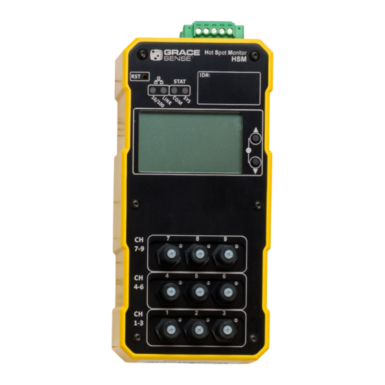
- Page 20 GraceSense Hot Spot Monitor D. Hardware Description 1. Physical Interface The HSM has the following physical features: a. Optical Fiber Connection Ports (9 or 18) b. Fiber Retention Nut c. Status LEDs d. Reset Button e. HSM Indicator LEDs Input Power Connection , RS-485 Serial Port g.
- Page 21 GraceSense Hot Spot Monitor 2. There are four HSM Indicator LEDs visible 3. Each channel has a small indicator LED. from the front of the HSM HSM Module. The The LED is used for indicating the status of meaning of the Indicator LEDs is shown in the sensor channel.
- Page 22 GraceSense Hot Spot Monitor Ch 4 Installation compartments are an ideal example as they cannot be viewed in operation. The installation of the GraceSense Hot Spot ™ Monitor (HSM) is comprised of several steps. 3. There must be a method for affixing one of The HSM Module and Fiber-Optic Probe can be the various fixture options to the Potential installed independently of each other, and hence...
- Page 23 GraceSense Hot Spot Monitor B. Secure Probe to Potential Failure Points – this aids in proper thermal conduction and (PFP) will result in more accurate readings. The most common Probe Mounting Fixture for Figure 10: Tyco/Amp Ring Style Lugs use with the HSM system is based on industry standard ring-style cable termination lugs.
- Page 24 GraceSense Hot Spot Monitor the probe tip into the end of the lug. Ensure NOTICE that the head of the probe-lock set screw is visible and easily accessible to allow it to be Once the fixture has been put in place, follow secured.
- Page 25 GraceSense Hot Spot Monitor 6. Validate that the probe is properly secured up to 120˚C (248˚F) and the fiber for into the lug by giving a gentle tug. At this temperatures up to 100˚C (212˚F). point the joint can be carefully dressed, if Temperatures in excess of these could required, while ensuring the probe is not cause premature failure of the fiber.
- Page 26 GraceSense Hot Spot Monitor Figure 17: Electrical Tape Installation WARNING Do not fasten or attach ANY mounting hardware (tie-wraps, etc.) to at least a 30 cm (12") length of fiber between the portion of the Probe at high voltage and its first non-energized point of contact.
- Page 27 GraceSense Hot Spot Monitor Figure 20: Safe Dielectric Routing Practices 5. Mark each end of the fiber with a means to identify each fiber when finalizing the installation. If this is not done, it can be very challenging to correlate installation location with the fiber.
- Page 28 GraceSense Hot Spot Monitor Figure 21: DIN Rail Clearances Figure 23: Removing HSM Module from DIN Rail 4” Clearance BriteSpot ID#: STAT E. Connect Network and Power Wiring 1) Power Requirements The HSM Module requires a 12-24VDC 4” Clearance voltage source to operate. Any industrial DC power source that provides power within the range specified can be used.
- Page 29 GraceSense Hot Spot Monitor shielded cable shall be used such as Belden CAUTION #3105. Table E Terminals 1-5 Ensure the power is turned OFF to prevent damage to the equipment prior to connecting Terminal Wire Wire Name Function the power of circuitry. Number Gauge Type...
- Page 30 GraceSense Hot Spot Monitor Figure 25: Typical Grounding via Grounded 6) Connect Communication Wiring Din Rail (MODBUS TCP/IP and ETHERNET I/P) Shielded twisted-pair 10/100 Base-T cables Ground Bus Metal Enclosure Wall (CAT5) with RJ45 connectors are supported. Connect cable to the Ethernet port on the device should either MODBUS TCP/IP or ETHERNET I/P protocols be selected for real-time communication with the device.
- Page 31 GraceSense Hot Spot Monitor Figure 27: Typical Serial Topology for HSM Modules. Once a section of MODBUS RTU fiber has been cut, it can only be cut shorter, therefore be careful to ensure that enough length has been allocated to reach the HSM Module. It is best to leave at least 25-50 mm (1-2") of extra fiber as a precautionary measure.
- Page 32 GraceSense Hot Spot Monitor Figure 30: Fiber Trimmed noticeable and does not require excessive force. Secure the Fiber Retention Nut with moderate force by screwing it in clockwise as shown in Figure 31. Do not over tighten the nut, as it is plastic and can be broken if too much force is applied.
- Page 33 GraceSense Hot Spot Monitor d. Ensure that Optical Signal is adequate once all the fibers are installed and connected, they must be checked to ensure that the optical signal is strong enough for proper operation of the device. Apply power to the device and wait several minutes for all probes to stabilize.
- Page 34 GraceSense Hot Spot Monitor Ch 5 Usage 2) LCD Interface (G-HSM-9SM Only) The HSM-9SM is equipped with a simple A. User Interface Overview LCD and set of buttons which allows for basic data display and configuration. 1) Web Interface Once connected to the HSM via the Figure 33: LCD Interface Navigation web interface, a host of information and configuration options are presented.
- Page 35 GraceSense Hot Spot Monitor Usage...
- Page 36 GraceSense Hot Spot Monitor B. Configuration ii. Network Configuration Any changes to the network 1) Web Interface configuration settings will Connecting to the Device automatically reboot the system. Connect a CAT5 Ethernet cable directly between the Ethernet ports on the Figure 36: Network Configuration Web Page computer and HSM to be configured.
- Page 37 GraceSense Hot Spot Monitor Figure 37: MODBUS Configuration Web page When updating the Warnings/ Thresholds, the “Update” button must be pressed to enter the changes into the memory of the device. Figure 38: Device Configuration Web page Table I MODBUS Configuration Web Page Settings Default Parameter...
- Page 38 GraceSense Hot Spot Monitor v. Administration Setup Figure 40: Device Parameters LCD Screen The Administration Setup is used for changing the Administration rights. The username and password must be known prior to changing any values. Figure 39: Administration Setup Web Page Table L Device Parameters HMI Screen Settings Default Parameter...
- Page 39 GraceSense Hot Spot Monitor Table M MODBUS RTU Parameters Table O Basic MODBUS Queries Default Parameter Range/Options Read Value Read Read Client Client ID 1, Type Client ID 1, Ch 1 19200 9600, 19200, 38400 ID 1, Ch 1 Ch 1 Baud Rate Temperature °F Baud...
- Page 40 GraceSense Hot Spot Monitor provide more detailed description when See Appendix A for details. problems arise. The status registers can be Example: Reading Input Register 30055 accessed via MODBUS (See Appendix A) or through the LCD screen (G-HSM-9SM only). Table R Example Warning Flag Input Register Integer Binary...
- Page 41 GraceSense Hot Spot Monitor can be viewed on the Alarm Status LCD Table U Relay Conditions Screen as shown in Figure 41. Contact Condition State Figure 41: Alarm Status LCD Screen All "relay enable" selected sensors readings Open are below the respective Alarm Setpoint Any one of "relay enable"...
- Page 42 GraceSense Hot Spot Monitor 4) Web interface Table V Error Code Table Figure 44 shows the main web interface Status Register Description page screen. Value OK - No action needed system OK Figure 44: HSM Web Interface WARNING – schedule maintenance of the equipment –...
- Page 43 GraceSense Hot Spot Monitor Figure 45: Log Information Table X Onboard Data Acquisition Timespans Log Rate Interval Memory Timespan 1 min 8 months 5 min 3 years 15 min 9 years 30 min 18 years 1 hour 36 years 2 hours 72 years 6 hours 216 years...
- Page 44 GraceSense Hot Spot Monitor Figure 46: Logging Information Webpage Figure 47: Confirming Log Erase G. Factory Reset Under some circumstances it may be desirable to return the HSM Module back to the factory configuration. In situations where the administrator password or IP address are lost are compromised, perform the reset procedure as outlined.
- Page 45 GraceSense Hot Spot Monitor Figure 48: Inserting Fiber into RST Button H. Firmware Upload Procedure for HSM Table Z Firmware Upload Procedure for HSM Procedure Start Boot-Loader e S p I D # B r it Software S T A S T A 60034 R S T...
- Page 46 GraceSense Hot Spot Monitor Ch 6 Troubleshooting off the surface of the LED inside the port with clean compressed A. Troubleshooting the Fiber-Optic Probes air. DO NOT USE UNFILTERED, 1. Problem: Sensor / Potential Failure Points NON-INSTRUMENTATION TYPE (PFP) mapping. The user is unsure about COMPRESSED AIR.
- Page 47 GraceSense Hot Spot Monitor APPENDIX A - MODBUS and EIP Memory Map MODBUS and EIP Memory Map Range: 30005 to 30016 Register Read/ Register Modbus EIP Offset Category Description Default Range, Format Register # Interpretations G-HSM-9M G-HSM-9SM G-HSM-18K Name Write Type Offset # Instances...
- Page 48 GraceSense Hot Spot Monitor MODBUS and EIP Memory Map (cont.) Range: 30038 to 30039 Register Read/ Register Modbus EIP Offset Category Description Default Range, Format Register # Interpretations G-HSM-9M G-HSM-9SM G-HSM-18K Name Write Type Offset # Instances Degree CF Degree C or F Flag (1=C, 2=F) 30038 (1=C, 2=F) HMI Settings...
- Page 49 GraceSense Hot Spot Monitor MODBUS and EIP Memory Map (cont.) Range: 30068 to 30079 Register Read/ Register Modbus EIP Offset Category Description Default Range, Format Register # Interpretations G-HSM-9M G-HSM-9SM G-HSM-18K Name Write Type Offset # Instances Low Word of Serial Number L S/N BS 1 30068 for BS1...
- Page 50 GraceSense Hot Spot Monitor MODBUS and EIP Memory Map (cont.) Range: 30098 to 30115 Register Read/ Register Modbus EIP Offset Category Description Default Range, Format Register # Interpretations G-HSM-9M G-HSM-9SM G-HSM-18K Name Write Type Offset # Instances Temp C 1 Temperature in C of Ch 1 30098 Temp C 2...
- Page 51 GraceSense Hot Spot Monitor MODBUS and EIP Memory Map (cont.) Range: 30134 to 30151 Register Read/ Register Modbus EIP Offset Category Description Default Range, Format Register # Interpretations G-HSM-9M G-HSM-9SM G-HSM-18K Name Write Type Offset # Instances Fib Power 1 Fiber Power of Ch 1 30134 Fib Power 2...
- Page 52 GraceSense Hot Spot Monitor MODBUS and EIP Memory Map (cont.) Range: 30341 to 30363 Register Read/ Register Modbus EIP Offset Category Description Default Range, Format Register # Interpretations G-HSM-9M G-HSM-9SM G-HSM-18K Name Write Type Offset # Instances Lower 16 Bits of the Serial IR_SN_LO_1 0-65535 30341...
- Page 53 GraceSense Hot Spot Monitor MODBUS and EIP Memory Map (cont.) Range: 30373 to 30395 Register Read/ Register Modbus EIP Offset Category Description Default Range, Format Register # Interpretations G-HSM-9M G-HSM-9SM G-HSM-18K Name Write Type Offset # Instances Lower 16 Bits of the Serial IR_SN_LO_2 0-65535 30373...
- Page 54 INSTRUCTION BULLETIN NO. HSM-IG-EN...
Need help?
Do you have a question about the GraceSense G-HSM-9SK-15M and is the answer not in the manual?
Questions and answers