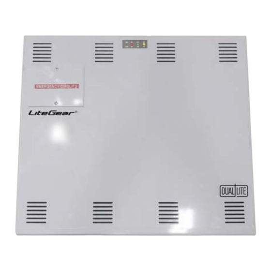
Hubbell DUAL LITE LiteGear LG375S Installation Instructions And User Manual
For 375va/375w & 600va/600w large-inverter power systems
Hide thumbs
Also See for DUAL LITE LiteGear LG375S:
- Installation instructions and user manual (16 pages)
Advertisement
Quick Links
Installation Instructions
and
User Manual
For
For 375VA/375W & 600VA/600W Large-Inverter Power Systems
Models:
LG Series
LG375S
LG600S
LG375SI
LG600SI
Surface Mounted Version
Surface Mounted Version
Surface Mounted Version w/Self-Test
Surface Mounted Version w/Self-Test
Advertisement

Summary of Contents for Hubbell DUAL LITE LiteGear LG375S
- Page 1 Installation Instructions User Manual LG Series For 375VA/375W & 600VA/600W Large-Inverter Power Systems Models: LG375S Surface Mounted Version LG600S Surface Mounted Version LG375SI Surface Mounted Version w/Self-Test LG600SI Surface Mounted Version w/Self-Test...
- Page 2 READ AND FOLLOW ALL SAFETY INSTRUCTIONS IMPORTANT SAFEGUARDS When using electrical equipment, basic safety precautions should always be followed, includ- ing the following: READ AND FOLLOW ALL SAFETY INSTRUCTIONS: • Do not use outdoors. • Do not let power supply cords touch hot surfaces. •...
- Page 3 Table of Contents Description Page Section 100 System Installation Instructions 101. Specifications ...................... 102. Receiving, Moving and Storing Systems and Batteries ........102.1 Shipping Damage ....................102.2 Temporary Storage of Units and Batteries ............103. Installation Requirement ..................103.1 Operating Environment ..................103.2 High Altitude Operation ..................
- Page 4 Section 100 System Installation Instructions 101. Specifications Input • Input voltage: Field Selectable 120 or 277Vac., (input voltage must be the same as output voltage). • Input frequency: 60HZ ±2% • Input surge protection: Meets UL 924 Output • Output voltage: Field Selectable 120 or 277Vac., 60HZ., (output voltage must be the same as input voltage).
- Page 5 102. Receiving, Moving and Storing Systems and Batteries 102.1 Shipping Damage Inverter system batteries are shipped inside unit inside a separate carton. Carefully inspect all cartons upon receipt for evidence of shipping damage. Notify carrier immediately of leaking or damaged cartons for possible concealed damage. 102.2 Temporary Storage of Units and Batteries For temporary storage of LG inverter systems and batteries prior to installation, select a clean, cool, dry location with normal ventilation for human habitation and level floors.
- Page 6 104.2 Mounting Hardware Mounting hardware is not provided. Care should be taken when selecting mounting hardware to ensure that it is the proper type for the application and sized to safely support the system's full weight when installed ensuring safe and secure attachment of system to wall surface or building structures. For ease of installation, the factory recommends that the head size of mounting screws or bolts be small enough to pass through the keyhole knockouts provided of mounting.
- Page 7 105.1 AC Wiring Preperations 1. Remove the system’s front cover. 2. Make sure the LG inverter system input and output voltages are correct for the particular appli- cation. Remember that the LG system provides single-phase power only. 3. The input circuit breaker in the input service panel provides the means for disconnecting AC to the LG inverter system.
- Page 8 - Connected fixture(s) can be externally switched and will Wiring Diagram D. NORMALLY ON LOADS NORMALLY OFF LOADS NORMALLY ON & OFF LOADS SWITCHED LOADS...
- Page 9 SWITCHED OR DIMMED EMERGENCY LOADS Note: ONLY (2) OF (4) POSSIBLE SWITCHED OR DIMMED CIRCUITS SHOWN SWITCHED OR DIMMED AND UNSWITCHED EMERGENCY LOADS Note: ONLY (2) OF (4) POSSIBLE SWITCHED OR DIMMED CIRCUITS SHOWN DIMMING OPTION CONTROL WIRING NOTE: Dimming switches are designed for independent settings to allow different emergency dimming control voltages for each circuit.
- Page 10 Table 2 Maximum Load (Watts) Output of all (4) 10.0 dimming circuits (Volts) Model Normal Emergency Normal Emergency Normal Emergency Normal Emergency Mode Mode Mode Mode Mode Mode Mode Mode 1350 LG375S-AO LG375SI-AO 1350 LG375S-AO-CB 1350 LG375SI-AO-CB 1350 LG600S-AO 2160 1080 LG600SI-AO 2160...
- Page 11 106.2 Battery Installation and Connection Battery Placement: The LG375S models are provided with (5) 12V Lead Calcium batteries (60Vdc string). The LG600S models are provided with (8) 12V Lead Calcium batteries (96Vdc string). LG375S: Carefully place all batteries in the unit battery (lower) compartment with positive (+) red terminals facing outwards and upwards.
- Page 13 106.3 Battery Voltage Check Using a digital volt-ohm meter, check for correct nominal battery voltage between DC Input NEG and POS wires. Volatge reading should be ±10% of system’s nominal 60Vdc for LG375S, 96Vdc for LG600S operating voltage. 107. Final Installation Checklist IMPORTANT: Before proceeding to the System Start-up Procedure (Section 108) complete the Final Installation Checklist below.
- Page 14 109.2 For LG375SI and LG600SI This model also provides for manual testing by pushing the TEST button in a specific pattern: Reaction and LED Indication Action Push test switch Once (within (2) seconds) (30) second test: one blink GREEN/pause Push test switch Twice (within (2) seconds) (30) minute test: two blinks GREEN/pause Push test swithc Three times (within (2) seconds) (90) minute test: three blinks GREEN/pause...
- Page 15 200. Maintenance 200.1 Safe Shut Down Procedure CAUTION: To avoid possible equipment damage or personal injury, assume that there is AC voltage present inside the LG inverter system unit any time AC input power or DC battery voltage is applied. The inverter is capable of providing output voltage from the batteries even when there is no AC input line voltage.
- Page 16 Dual-Lite • www.dual-lite.com A Hubbell Lighting, Inc. brand with representatives’ offices in principal cities throughout North America. Copyright Hubbell Lighitng, Inc., All Rights Reserved • Specifications subject to change without notice. • Printed in U.S.A. © 18000097 1/20...

Need help?
Do you have a question about the DUAL LITE LiteGear LG375S and is the answer not in the manual?
Questions and answers