Advertisement
Quick Links
Advertisement

Related Manuals for RUN ATTACK ATTACK19915

Summary of Contents for RUN ATTACK ATTACK19915
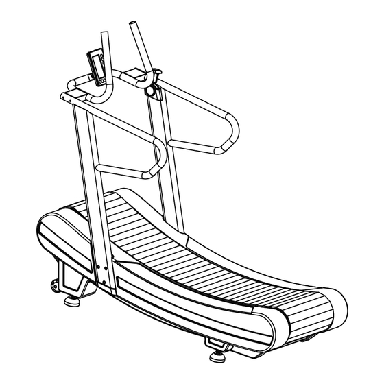
- Page 1 ATTACK19915 Curve-Manual Treadmills USER MAN UAL...
- Page 2 IMPORTANT SAFETY INSTRUCTION To maximize the benefit and safety of your treadmill training we strongly recommend all users maintain proper running form and not shuffle their feet.When servicing any piece of fitness equipment, basic precautions must be followed. Familiarize yourself with all warnings, instructions and procedures concerning proper care and maintenance of the treadmill.
- Page 3 TABLE OF CONTENTS ......................PARTS INVENTORY ....................ASSEMBLY INSTRUCTION ......................DISPLAY OVERVIEW ..................... RESISTANCE ADJUSTMENT ......................BEFORE WORKOUT ......................EXPLODE DRAWING ......................... PARTS LIST BEFORE ASSEMBLING Always follow the steps in this manual as you assemble your machine. Do not skip, substitute or modify any steps or procedures of this assembly,as doing so could result in personal injury and will void your warranty.
- Page 4 PARTS INVENTORY ITEM DESCRIPTION Q'TY Main Frame Console Mast- Left Console Mast- Right Handlebar Set Console HARDWARE KIT HARDWARE KIT Hex Socket Button Head Screws M10x50L(6pcs) Hex Socket Button Head Screws M8x55L(4pcs) Curved Washer M8(4pcs) Allen key M6(1pc) Allen key M5(1pc) COMPONENT DIAGRAM Handlebar Console...
- Page 5 ASSEMBLY INSTRUCTIONS Step 1. Leveling the treadmill. To adjust the Universal adjustable pad in the bottom of main frame until pads firmly flat on the ground or floor. Universal adjustable pad x 4 pcs WARNING: It’s extremely important that pads are correctly adjust to proper postions. An unbalanced unit may cause running belt misalignment or other issues.
- Page 6 Step 4. Assemble the handlebar set. Use Hex Socket Button Head Screws M8 x 50L and Curved Washers to mount the handlebar between left console mast and right console mast. ※Connect RPM and resistance wires then put connections inside the tube.. Hex Socket Button Head Screws M8 x 55L x 4 pcs Curved Washer M8 x 4 pcs...
- Page 7 TREADMILL INSTALLATION LOCATION REQUIREMENT Place the treadmill on a level and stable surface away 12” 300mm from direct sunlight. The intense UV light can cause discoloration on the plastics. Locate your treadmill in an area with cool temperatures and low humidity. 24”...
- Page 8 DISPLAY OVERVIEW A. Input Power Install 4 pcs AA battery to the computer, there will produce a beep sound then turn on the computer at standby mode. B. Sleep Mode The computer will enter Sleep Mode (LCD off) when there is no signal input or no key is pressed after 1 minute.
- Page 9 C-2. KEY FUNCTIONS Start : Press “Start” key to begin your workout at standby mode. START Stop : First pressing is to pause the function, press “Start” to continue the function or press STOP ”Stop” back to standby mode. Enter : During the setting mode (after pressing program key), press the key to save the setting.
- Page 10 target (2) Target - time : time 1. Press “Target time” key to set up the time value by using “UP” and “DOWN” keys. 2. Press “Enter” key to save the setting. 3. Press “Start” key to begin your workout. Once the time has reached your goal, computer will go beeping and reset itself to default setting.
- Page 11 COMPUTER BATTERY REPLACEMENT To test the computer batteries, drive the running belt until the computer “wakes up”. If the battery is low, to unscrew the back of the compouter and detach the battery cap in the back of the computer and remove old AA batteries and replace with a set of two new AA batteries.
- Page 12 BEFORE WORKOUT WARNING: There are something you need to know before workout. One Way Drive Mechanism The non-motorized running surface is designed for the user to control and actually drive or turn the belt. For the safety of user, the running surface only rotates in one motion that allows for forward running use of the machine (as opposed to reverse).
- Page 13 EXPLODE DRAWING D02 x 4 pcs B03 B04...
- Page 14 PART LIST Part No Description Qt'y Drawing No BOM Code Main frame AT34-A01AA SR0134A01AA Side cover-Left AT34-A02BA SR0134A02BA Side cover-Right AT34-A03BA SR0134A03BA universal adjusting pad AT34-A04AA MT0134A04AA Mobile handle AT34-A05AA SR0134A05AA Non-Slip rubber pad AT34-A06AA MB0134A06AA Support tube AT34-A08AA SR0134A08AA Rubber pad AT01-C02A MB0101C02A...
- Page 15 PART LIST Part No Description Qt'y Drawing No BOM Code Left console mast AT34-E01AA SR0134E01AA Right console mast AT34-E02AA SR0134E02AA End cap of handle AT01-E13A MB0201E13A Part No Description Qt'y Drawing No BOM Code Console handlebar AT34-F01AA SM0134F01AA Overlay AT34-F01AA-01 EL0134F02AA-01 Console AT34-F02BA...
- Page 16 Curve-Manual Treadmills USER MANUAL...
Need help?
Do you have a question about the ATTACK19915 and is the answer not in the manual?
Questions and answers