Advertisement
Quick Links
Advertisement

Subscribe to Our Youtube Channel
Summary of Contents for Microsensor MPM583
- Page 1 MPM583 Operation Manual V2.0...
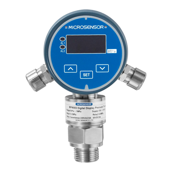
- Page 3 Pressure Transmitter is one of precise instruments. We suggest you to read this manual carefully before use. 1 Introduction MPM583 pressure switch is an intelligent digital display pressure & controlling device which integrates function of pressure measuring, displaying and controlling into one product. It is an electronics switch. A piezo-resistive pressure sensor with isolated diaphragm is used in front of the switch.
- Page 4 building material, hydrogeology and other country economic fields. The products measurement tools type approval No. 15F139-61. 2 Basic Operating Principles DC24V power input power regulation pressure constant display current display calculation circuit signal amplify relay interface sensor and A/D switch circuit convert Fig.1...
- Page 5 be calculated by the micro processor to achieve the display and control of the pressure. Interface Part: Use two relays provide output controlling signal, each relay offer a constant open point and a close point; the relay mode indicate on the control panel. 3 Specifications Measuring Range: -0.1 MPa…0 MPa~0.01 MPa…100MPa Power Supply: 13V~31V DC(Recommend 24VDC)
- Page 6 Relay Touch Capacity: 220VAC/3A,30VDC/3A Relay Touch Point Longevity: ->100000 times Relay Touch Point Quantity: -AL1 1NO+1NC ; AL2 1NO+1NC Display Part Parameter: Displaying Character: 4 bits 0.36”red nixie tube Displaying Range: -1999~9999 Collecting Speed: about 5times/second Internal Resolution: 16bits Installing Mode: Vertical InstallationCompensation 4 Outline Construction and Installation 4.1 Construction Materials: Pressure port: stainless steel...
- Page 7 ~100 φ32 SW27 φ6 M20×1.5-6g Fig. 2 4.4 Installation In receipt of this product, please carefully read this operating manual, understand the relative specifications, then do check and accept and installation under the instruction of this manual. 4.4.1 Installation It can be directly installed on the local pressure port via a supported connection pipe.
- Page 8 there is no effects to range. Standard installation is to make displaying screen directly and flatly face to the observer. 4.4.2 Electrical Connection The definition to terminals is as below figures (Back View Figure) A l a r m 1 A l a r m 2 D C 2 4 V Fig.3...
- Page 9 Terminal 7#--- Close for Alarm2 Terminal 8#--- Open for Alarm 2 Notes: (1) The power supply is 24VDC, assure a right supply and correct wire connection. (2)The internal Connection Terminal is fast type, needn’t use screwdriver , just push down the flexible block on the top of Terminals, peel off the wire skin, tightly screw the wires and put it into the wire connection hole, then loose the flexible block on the top of pins to connect.
- Page 10 Continuously Press"▲" or"▼"key, some menus have double hit function, the set data plus or minus automatically, and there is function of speed shifting and pace shifting according to the press time. "SET"key is to open function menus or confirm the data. 4.4.4 Setting Functions Turn on the device, it will display the version number, then enter measuring mode.
- Page 11 press SET over user password setting 3 seconds 0001 factory normal password PASS measurement setting wrong password Fig.4 4.4.5 Function Introduction of Each Parts 4.4.5.1 Password Setting Under normal measuring mode, press“SET” over 3seconds , screen displays“PASS”,press“▲”or“▼”, display initial password 0000,modify the password as your desire.
- Page 12 Fig.5 Description: (1) AL-1: is limit value of relay AL1, on condition that password is 0001, press SET key to display menu“AL-1”, press“▲”or“▼” to modify , the modified range is between the calibrating value from Zero to FS. Press“SET” to confirm and enter next menu“AL1C”. (2) AL1C: is controlling circle difference value of relay AL1, the modified range is between the calibrating value from Zero to FS.
- Page 13 The operating menu is as below: password-xxx AD-H DA-1 DA-2 P6A- AD-L AL2F DISL DISH LI_E AL1F normal D--P AL-1 AL1C AL-2 AL2C measurement Fig.6 4.4.6 Factory Setting Area including User Area Operation Description: (1) DA-1:product serial number, defined by factory. (2) DA-2:production time: year, month, e.g.: 0607, means July of 2006.
- Page 14 change or adjust. (4) AD-L: this data is automatically collected by the device, no need to input any more. When this menu appears, press“▲”or“▼”, screen displays the collected original AD value, at this time, should add zero pressure to transducer, when display value keep stable, press“SET” to collect this data.
- Page 15 the actual linearity, if the actual curve is as the upper curve,“LI_E”should be a negative value; if the curve is as the lower curve,“LI_E”should be a positive value. The data can be modified between -127~127. display upper curve low er curve pressure Fig.7 (9) AL1F: Relay AL1 alarm mode controlling number,the data can be...
- Page 16 at hundred position, 3 represents decimal point at thousand position. ●★Next menu enter the user setting area, please see the setting method of user setting area. ★Attentions during the setting: (1) The user can modify and store all the data by “SET”,“▲”and“▼”. (2) When one menu appears, press“SET”key to jump directly to the next menu, press“▲”or“▼”to open it ;...
- Page 17 options. 4.4.7 Zero Point Calibration On condition of normal measuring mode, when add Zero point pressure to sensor, simultaneously pressing“▲”and“▼” may clear the sensor Zero point value. This operation will correct the possible errors caused by installation or surrounding and will not affect the FS value. This function is just for amending the slight changes on Zero point, it cannot be used for range elevation.
- Page 18 Be sure unpacking carefully, and prevent damaging instruments or accessories. 6.2 Enclosed The transmitter should be enclosed when out of factory: MPM583 pressure switch Production Manual Production Qualification Certificate 6.3 Storage The transmitter should be stored in dry ventilate room, ambient temperature -40℃~85℃and the relative humidity≤85%, no corrosive...
Need help?
Do you have a question about the MPM583 and is the answer not in the manual?
Questions and answers