
Related Manuals for J&E Hall HallScrew HSS 3100 Series

Summary of Contents for J&E Hall HallScrew HSS 3100 Series
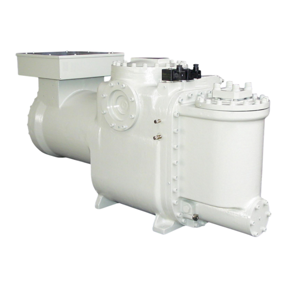
- Page 1 HallScrew HSS 3100 Series Semi-hermetic Integral Single Screw Compressors HSS 3118, HSS 3120, HSS 3121 and HSS 3122 Installation, Operation and Maintenance Manual...
- Page 2 HSS 3100 Series Operators Manual © J & E Hall International 2011 All rights reserved. No part of this publication may be reproduced or transmitted in any form or by any means, electronic or mechanical, including photocopying, recording or by any information storage or retrieval system, without permission in writing from the copyright holder.
-
Page 3: Safety
HSS 3100 Series Operators Manual Safety In common with most other forms of mechanical and electrical equipment, there are a number of potential hazards associated with operating and servicing refrigeration plant. In writing this instruction manual every emphasis has been given to safe methods of working. -
Page 4: Examination Of Pressure Systems
HSS 3100 Series Operators Manual WARNING As described in 4.1. Slide Valve Actuation, the capacity control mechanism contains a heavy duty spring under compression. Any attempt to remove the spring without using the correct tools could result in serious injury to the operator. -
Page 5: Lubricating Oils
HSS 3100 Series Operators Manual Lubricating Oils Refrigeration oils are unlikely to present any significant health and safety hazard provided they are used properly, and good standards of industrial and personal hygiene are maintained. The following general precautions are recommended: •... -
Page 6: Table Of Contents
HSS 3100 Series Operators Manual Contents Safety ............................ 3 Personnel Permitted to Install, Commission and Maintain the Plant ........3 Mechanical ..........................3 Examination of Pressure Systems ..................4 Noise Hazard ........................... 4 Electrical ..........................4 Lubricating Oils ........................5 Hydrochlorofluorocarbon and Hydrofluorocarbon Refrigerants .......... - Page 7 HSS 3100 Series Operators Manual Compressor Cooling ....................25 7.1. Liquid Injection Control and Economiser Connections ............25 7.1.1. Fitting the Liquid Injection Orifice Plug ................26 3N1 Three Function Valve for HSS 3100 Series Compressors (R134a Only) ..30 Integration into the Refrigeration Circuit ..............
-
Page 8: List Of Figures
HSS 3100 Series Operators Manual 15.5.3. Monthly .......................... 51 15.5.4. Every Year, or at Intervals of 5,000 Operating Hours............. 51 15.5.5. Every 3 Years, or at Intervals of 15,000 Operating Hours ..........52 15.5.6. Every 6 Years, or at Intervals of 25,000 Operating Hours ..........52 15.5.7. -
Page 9: About This Publication
HSS 3100 Series Operators Manual About this Publication These instructions have been prepared according to the following standards: BS 4884 : Technical Manuals: Part 1 : 1992 Specification for Presentation of Essential Information. Part 2 : 1993 Guide to Content. Part 3 : 1993 Guide to Presentation. -
Page 10: Misuses That Invalidate Guarantee
HSS 3100 Series Operators Manual Misuses that Invalidate Guarantee Please note that the installer is responsible for the correct installation and commissioning of equipment and, on completion, the owner and/or user is responsible for its safe operation and maintenance. Failure to comply with the following provisions will invalidate the guarantee as set out in J &... -
Page 11: Prolonged Storage
HSS 3100 Series Operators Manual 2.3. Prolonged Storage If, for any reason, the compressor cannot be installed immediately and must be placed in prolonged storage, refer to 10. Prolonged Storage. 2.4. Commissioning Provisions General commissioning procedures are described in 12. Commissioning and Operation. -
Page 12: General Description
HSS 3100 Series Operators Manual General Description The J & E Hall International HSS 3100 series of semi-hermetic integral compressors are the latest addition to the HallScrew family of oil injected, positive displacement, single screw compressors. Reflecting the very latest innovations in screw compressor technology, they are designed for incorporation into factory built DX chillers using R407c, R134a or R22, having independent refrigeration circuits for each compressor. - Page 13 HSS 3100 Series Operators Manual The compressor consists of two cast-iron castings which are bolted together. The first casting is divided into two parts: the main casing, encloses the motion work comprising the main rotor and star rotor, the motor housing encloses the 3 phase, 2 pole motor. Returning suction vapour flows around the stator/rotor unit, cooling the windings in the process, before entering the main rotor flutes.
-
Page 14: Internal Relief Valve
HSS 3100 Series Operators Manual The integral oil separator is fitted with a built-in discharge check valve. As an option, for R134a applications only, the discharge connection can be fitted with a specially designed valve which combines the functions of a stop valve, non-return valve and head pressure control valve in one compact assembly;... -
Page 15: List Of Figures Fig 1 Compression Process
HSS 3100 Series Operators Manual 1. and 2. Suction Main rotor flutes 'a', 'b' and 'c' are in communication at one end with the suction chamber via the bevelled rotor end face, and are sealed at the other end by the star rotor teeth. -
Page 16: Capacity Control And Volume Ratio
HSS 3100 Series Operators Manual Capacity Control and Volume Ratio HallScrew HSS 3100 series compressors is provided with infinitely variable capacity control as standard. Since the HallScrew compressor utilises fixed intake and discharge ports instead of valves, the overall compression ratio is determined by the configuration of these ports. -
Page 17: Slide Valve Actuation
HSS 3100 Series Operators Manual 4.1. Slide Valve Actuation The method of operation is illustrated in Fig 3. One end of the slide valve is machined to form a hydraulic piston, housed inside a cylinder and mounted internally at the discharge end of the compressor. -
Page 18: Capacity Control By Inverter Drive
HSS 3100 Series Operators Manual Spring Expands Oil Supply Oil Vent Unload De-energised Energised (Closed) (Open) Discharge pressure acts Compressor Unloading on this side of piston Spring Force + Discharge Pressure > Cylinder Pressure = Slide Valve Moves Towards Unload Spring Compressed Oil Supply... -
Page 19: Inverter Size
HSS 3100 Series Operators Manual • Remove the plunger from the load solenoid valve (only) and do not fit the coils. When using an inverter, it is of utmost importance that it is both sized and set up correctly. 4.3.1. Inverter Size The inverter must be sized to deliver the maximum current taken by the compressor motor at the maximum power conditions –... -
Page 20: Fig 4 Lvdt Arrangement And Wiring Connections
HSS 3100 Series Operators Manual DIN Plug IP65 Indicator Cable Entry + 24 V dc supply - 0 V dc (common) 4 to 20 mA signal No connection Link Terminals 152 and 154 DIN Plug Connector Connections to J & E Hall International Fridgewatch 2000 and 2100 Controllers Fig 4 LVDT Arrangement and Wiring Connections Page 20 of 78... -
Page 21: Compressor Lubrication, Sealing And Cooling
HSS 3100 Series Operators Manual Compressor Lubrication, Sealing and Cooling HSS 3100 series compressors are fitted with an integral oil separator and oil filter. The oil performs three basic functions: 5.1. Capacity Control Actuation Oil pressure is used to actuate the compressor capacity control mechanism;... -
Page 22: Oil Support System
HSS 3100 Series Operators Manual Oil Support System HSS 3100 series compressors are fitted with an integral oil separator and oil filter. The system into which the compressor is to be installed must fully comply with the recommendations in 6.1. to 6.5. -
Page 23: Odp1
HSS 3100 Series Operators Manual Under normal operating conditions this oil is supplied via the difference in pressure between discharge and suction pressures. On starting the suction/discharge pressure differential across the compressor builds rapidly. However, this pressure difference must be monitored to ensure it achieves the correct value within a specified time. -
Page 24: Lubricating Oils
HSS 3100 Series Operators Manual In circumstances where the minimum discharge pressure is difficult to achieve, it is recommend to use the J & E Hall International three function valve; refer to 8.3N1 Three Function Valve for HSS 3100 Series Compressors (R134a Only). -
Page 25: Compressor Cooling
HSS 3100 Series Operators Manual Compressor Cooling The standard method of cooling for HSS 3100 series compressors is by direct injection of liquid refrigerant into the compressor main rotor flute, part-way through the compression process. In some circumstances no cooling is required. Alternatively, where the liquid injection load is significant, an external oil cooling system can be used to enhance efficiency. -
Page 26: Fitting The Liquid Injection Orifice Plug
HSS 3100 Series Operators Manual Diagram C: R134a Applications – Liquid Injection Only Fit special orifice plug part number 3313141 supplied with the compressor. The plug fits into a 7/8” UNF port located behind the connection block on the side of the compressor. Connect the liquid supply for injection to the ¾”... -
Page 27: Fig 6 Liquid Injection And Economiser Arrangements
HSS 3100 Series Operators Manual Discharge Liquid injection/economiser connection block on side of compressor Diagram A: No Cooling or External Oil Cooling – Economiser Not Used Return from Economiser Discharge 100 mm minimum to ensure oil trapping 7/8” – 14 UNF Economiser Liquid injection/economiser connection block on side of compressor... - Page 28 HSS 3100 Series Operators Manual 100 mm minimum Liquid Supply to ensure oil For Injection trapping Discharge ¾” – 16 UNF Liquid Injection Liquid injection/economiser connection block on side of compressor Diagram D: R22 and R407c Applications – Liquid Injection Only Return from Economiser Liquid Supply...
-
Page 29: Fig 7 Fitting The Liquid Injection Orifice Plug
HSS 3100 Series Operators Manual Unscrew and remove four hex head screws. Lift away the liquid injection/economiser connection block. The economiser baffle in-situ. Remove the economiser baffle. Note the gaskets, one each side. The liquid injection orifice plug is screwed into the The liquid injection orifice plug, note the ‘O’... -
Page 30: N1 Three Function Valve For Hss 3100 Series Compressors (R134A Only)
HSS 3100 Series Operators Manual 3N1 Three Function Valve for HSS 3100 Series Compressors (R134a Only) As an option, for R134a applications only, the discharge connection can be fitted with a specially designed valve which combines the following functions in one compact assembly. •... -
Page 31: Integration Into The Refrigeration Circuit
HSS 3100 Series Operators Manual Integration into the Refrigeration Circuit The HSS 3100 compressor is an oil injected screw type. The integral oil separator is a cyclone type and works on a centrifuge principle. Oil separators are not 100 % efficient, so the system must be designed to return any oil carried over into the system from the separator, back to the compressor. -
Page 32: Prolonged Storage
HSS 3100 Series Operators Manual Prolonged Storage In certain cases, it may be necessary to keep the compressor in store for several months before installation and commissioning takes place. In this event, the following precautions should be taken. 10.1. Placing the Compressor into Store The store area must be weatherproof, well ventilated, warm and dry. -
Page 33: Installing The Compressor
HSS 3100 Series Operators Manual Installing the Compressor The following instructions apply to ‘bare’ compressors; adapt as necessary if the compressor forms part of a package unit. If the compressor has been in prolonged storage, carry out the instructions described under 10.2. Taking the Compressor out of Storage, before installation takes place. -
Page 34: Making Connections
HSS 3100 Series Operators Manual CAUTION To prevent the nuts working loose during operation, use nuts with nylon inserts (stiff nuts) or secure with Loctite thread sealer. 11.1.1. Making Connections Refer to Appendix 1 Compressor Data. Carefully purge the holding charge of nitrogen from the compressor. -
Page 35: Leak Testing, Evacuation And Charging
HSS 3100 Series Operators Manual 11.4. Leak Testing, Evacuation and Charging Leak testing and evacuation are described in the following publications available from J & E Hall International: • Part D : Strength and Tightness Testing. • Part E : Evacuation and Dehydration. Before the compressor/system evacuation process commences, energise (open) capacity control solenoid valve A. -
Page 36: Fig 10 Motor Terminal Box Wiring: Star/Delta
HSS 3100 Series Operators Manual NOTE: circuit must be connected as shown to ensure correct rotation of the motor/compressor Motor thermistors T1 and T2 (supplied) Motor Terminal Plate Fuse Limit of J & E Hall Supply Reset Motor and discharge thermistors may be connected in series. -
Page 37: Fig 11 Motor Terminal Box Wiring: Soft-Start And Inverter Drive
HSS 3100 Series Operators Manual For applications using a soft-starter or inverter, equipment must be carefully selected to match the operating Soft-start or inverter conditions and must be able to Motor thermistors T1 accelerate the compressor smoothly and T2 (supplied) to full load/speed without stalling. -
Page 38: Commissioning And Operation
HSS 3100 Series Operators Manual Commissioning and Operation If the compressor is supplied as part of a package unit supplied by J & E Hall International, refer to Section 1 of the plant instruction manual for detailed installation and commissioning instructions. The instructions included in this part of the manual cover compressors supplied for incorporation into package units or site erected systems. -
Page 39: Checking Compressor Rotation
HSS 3100 Series Operators Manual Repeat this check for the thermistor that may be fitted in the oil injection/lubrication line. Check that stop valves isolating pressure gauges, cut-outs or other pressure controls are fully open. These valves should be locked- open using circlips or equivalent locking devices. - Page 40 HSS 3100 Series Operators Manual If an oil heater thermostat is fitted, the thermostat should maintain the oil at the correct temperature. Open the suction and discharge stop valves. WARNING The compressor must NEVER be started with the discharge stop valve closed or partially closed, nor must the discharge stop valve be throttled when the compressor is running.
-
Page 41: Normal Starting And Running
HSS 3100 Series Operators Manual After the compressor has started and been in operation for a short time, allowing sufficient time for the system oil injection pressure/suction pressure differential to become established, ODP1 is brought into circuit. ODP1 will stop the compressor motor if the system pressure differential falls to the trip setting. -
Page 42: Adding Oil To The System
HSS 3100 Series Operators Manual WARNING The compressor must NEVER be started with the discharge stop valve closed or partially closed, nor must the discharge stop valve be throttled when the compressor is running. Check that the stop valves in the rest of the refrigeration system are in their correct running positions. -
Page 43: Running-In The Compressor
HSS 3100 Series Operators Manual Running-In the Compressor These procedures are carried out during the plant’s first 200 hours of operation. Depending on circumstances, this time period may need to be extended. 13.1. Filters and Strainers Refrigerant tends to have a scouring effect on the internal surfaces of the system. -
Page 44: Refrigerant Filter/Drier
HSS 3100 Series Operators Manual Unscrew and remove the capscrews securing the filter cover. Lift away the cover and joint. Remove and discard the dirty filter element. Use a wad of lint free rag to remove any dirt, sediment etc., from inside the filter housing. -
Page 45: Checking For Leaks
HSS 3100 Series Operators Manual For polyolester synthetic lubricants, used with HFC refrigerants, maintain the acid number of the compressor lubricating oil <0.15 by checking the oil on a regular basis using a proprietary acid test kit available from the oil supplier. -
Page 46: Pumping Down And Opening Up The Compressor
HSS 3100 Series Operators Manual Pumping Down and Opening Up the Compressor WARNING Before opening up any part of the system, all personnel concerned must be aware of the potential hazards involved. Because safety is such an important topic, personnel should be thoroughly acquainted with the principles laid down in Safety. -
Page 47: Removing The Residual Refrigerant Gas
HSS 3100 Series Operators Manual WARNING Withdraw the fuses from the motor starter and keep them on your person so that they cannot be accidentally refitted, place a warning notice on the panel next to the main isolator. Disconnect the electrical supply to the compressor drive motor. - Page 48 HSS 3100 Series Operators Manual Once the leak test has proved satisfactory, evacuate and dehydrate the compressor and all other parts of the system open to atmosphere. Adopt the procedures described in publication Part E : Evacuation and Dehydration, available from J & E Hall International. Reconnect the electrical supply to the compressor motor.
-
Page 49: Maintenance
HSS 3100 Series Operators Manual Maintenance Routine maintenance is essential for the optimum availability and performance of all mechanical equipment, however, in this respect, refrigeration plant is in a somewhat different category since it is particularly susceptible to the presence of air and moisture inside the system, especially when the installation is fitted with a semi-hermetic compressor. -
Page 50: Running-In
HSS 3100 Series Operators Manual OCATION ILTER OR TRAINER Compressor suction line (if fitted). Compressor suction end cover. Strainer forms integral part of compressor Compressor liquid injection line - liquid injection cooling fitted. Economiser (subcooler) line before the solenoid valve and thermostatic expansion valve - if economiser fitted. -
Page 51: Weekly
HSS 3100 Series Operators Manual • Oil temperature measured at the oil cooler outlet (if an oil cooler is fitted instead of liquid injection). • The net oil pressure drop across the external oil filter (if fitted). • Suction and discharge pressures and temperatures. Gauge and temperature readings should be checked regularly, in addition to routine logging, and any variations from normal promptly investigated. -
Page 52: Every 3 Years, Or At Intervals Of 15,000 Operating Hours
HSS 3100 Series Operators Manual Experience of running the plant may suggest that more frequent cleaning is necessary. Renew the refrigerant filter/drier cores. Drier cores should be changed at earlier intervals if the cores become choked, or the amount of moisture in the system reaches a dangerous level. The sight-glass/moisture indicator will show evidence of contamination. -
Page 53: Every 24 Years, Or At Intervals Of 100,000 Operating Hours
HSS 3100 Series Operators Manual Check the operation of the capacity control mechanism for ‘drifting’ from the required slide valve position. If ‘drifting’ is occurring and the capacity control solenoid valve(s) are in good condition and appear to be working correctly, renew the glide ring/’O’ ring seal on the capacity control hydraulic piston. -
Page 54: Table 2 Maintenance Check List
HSS 3100 Series Operators Manual AILY Check the oil separator/reservoir oil level. 15.5.1. Check and record system temperatures, pressures and flow rates. EEKLY Check for leakage of refrigerant and oil. Inspect the exterior of the plant for damage or corrosion. Check valve caps are in place. -
Page 55: Oil Acid Content Record
HSS 3100 Series Operators Manual 15.7. Oil Acid Content Record Each time the oil’s acid content is checked, record the value in Table 3. IGNATURE RINTED ONTENT Table 3 Oil Acid Content Record Issue 2.2 : 07/11 Publication 2-126 Page 55 of 78... -
Page 56: Appendix 1 Compressor Data
HSS 3100 Series Operators Manual Appendix 1 Compressor Data • HSS 3100 Series: Compressor Model Nomenclature. • HSS 3100 Series: Physical Data. • HSS 3100 Series: Motor Data - 50 Hz Operation. • HSS 3100 Series: Motor Data - 60 Hz Operation. •... - Page 57 HSS 3100 Series Operators Manual HSS 3100 Series: Compressor Model Nomenclature Application Semi-hermetic compressor for air conditioning application Compressor Series 3100 Single Star 18, 20, 21 or 22 Capacity Control Slide V 2.2 V (on request) 3.0 V (standard) Lubricant Ester oil Mineral oil Motor Power (Nominal)
- Page 58 HSS 3100 Series Operators Manual HSS 3100 Series: Physical Data Compressor Type Single screw, integral, semi-hermetic. Compressor Rotation Clockwise looking on the motor end. Under no circumstances should the compressor run in the reverse direction. Method of Drive Suction gas cooled 3-phase, 2-pole stator/rotor arranged for start/delta, soft-start or inverter drive.
- Page 59 HSS 3100 Series Operators Manual HSS 3100 Series: Motor Data – 50 Hz Operation @ 50 H (2980 HSS 3118 HSS 3120 OMPRESSOR UNNING Motor nominal output (kW) Refrigerant R134 R407 R134 R407 C AND C AND Motor maximum input (kW) Maximum running current (A) @ 400 V Starting current (locked rotor) in Y (A) @ 400 V Starting current (locked rotor) in ∆...
- Page 60 HSS 3100 Series Operators Manual HSS 3100 Series: Limits of Operation Pressure Limits The pressure limits detailed below MUST NOT be exceeded during installation, commissioning or operation of the plant. Refer to Appendix 3 Limits of Operation Envelopes for further details. R134a R407c Maximum Design Pressures...
- Page 61 HSS 3100 Series Operators Manual Safety Requirements for Compressor Protection Parameter Trip Device Setting Remarks Discharge pressure High HP cut-out According to the Connected to compressor operating conditions discharge Discharge pressure Pressure control or pressure According to the transducer and programmable operating conditions controller with suitable analogue inputs...
- Page 62 HSS 3100 Series Operators Manual HSS 3100 Series: Physical Dimensions and Connections Rotor/shaft assembly HT Cut-out Lifting Eyebolt removal = 750 mm Slide Valve Position LVDT (optional) Economiser Oil Pressure Gauge Liquid Injection Stator removal = 600 mm Oil filter removal = 130 mm Unload Solenoid Valve 3N1 Valve Suction...
- Page 63 HSS 3100 Series Operators Manual Suction Gauge Connection View on arrow X Oil Drain Oil Heater Discharge Star assembly removal = 250 mm View on arrow Y Economiser Sight-glass (top) Oil Return From External Cooler (If Fitted) Oil Filter Oil Temperature Sensor Cover Pocket.
-
Page 64: Appendix 2 Oil Support System Schematic Flow Diagram
HSS 3100 Series Operators Manual Appendix 2 Oil Support System Schematic Flow Diagram Suction Discharge PSHH PSLL Evacuation Suction Discharge HT (Del) Integral Discharge Non-return Valve HT (Oil) Normally Closed Normally Open Locked Open Normally Closed Valve and Capped Valve, straight through Valve, right angle Strainer Non-return valve... -
Page 65: Appendix 3 Limits Of Operation Envelopes
HSS 3100 Series Operators Manual Appendix 3 Limits of Operation Envelopes Limits of Operation R134a - Standard 43 kW Motor: HSS 3118 and HSS 3120 60 kW Motor: HSS 3121 and HSS 3122 3.0 V Ask J & E Hall International about availability of 2.2 V slide for applications below this line... - Page 66 HSS 3100 Series Operators Manual Limits of Operation R134a - Economised 43 kW Motor: HSS 3118 and HSS 3120 60 kW Motor: HSS 3121 and HSS 3122 3.0 V Suction Gauge ° ° ° ° C This diagram is approximate, for guidance only. Refer to HallScrew selection software for definitive envelopes. Page 66 of 78 Publication 2-126 Issue 2.2 : 07/11...
- Page 67 HSS 3100 Series Operators Manual Limits of Operation R407c - Standard 60 kW Motor: HSS 3118 and HSS 3120 82 kW Motor: HSS 3121 and HSS 3122 3.0 V Ask J & E Hall International about availability of 2.2 V slide for applications below this line Suction Gauge °...
- Page 68 HSS 3100 Series Operators Manual Limits of Operation R407c - Economised 60 kW Motor: HSS 3118 and HSS 3120 82 kW Motor: HSS 3121 and HSS 3122 3.0 V Suction Gauge ° ° ° ° C This diagram is approximate, for guidance only. Refer to HallScrew selection software for definitive envelopes. Page 68 of 78 Publication 2-126 Issue 2.2 : 07/11...
- Page 69 HSS 3100 Series Operators Manual Limits of Operation R22 - Standard 60 kW Motor: HSS 3118 and HSS 3120 82 kW Motor: HSS 3121 and HSS 3122 3.0 V Ask J & E Hall International about availability of 2.2 V slide for applications below this line Suction Gauge °...
- Page 70 HSS 3100 Series Operators Manual Limits of Operation R22 - Economised 60 kW Motor: HSS 3118 and HSS 3120 82 kW Motor: HSS 3121 and HSS 3122 3.0 V Suction Gauge ° ° ° ° C This diagram is approximate, for guidance only. Refer to HallScrew selection software for definitive envelopes. Page 70 of 78 Publication 2-126 Issue 2.2 : 07/11...
-
Page 71: Appendix 4 Compressor Performance Data
HSS 3100 Series Operators Manual Appendix 4 Compressor Performance Data For detailed selection use the J & E Hall International HallScrew compressor selection software, available on CD. Continuous research and development may necessitate changes to specifications and data in this Application Manual and the J &... -
Page 72: Appendix 5 Hs 3100 Series Compressor Replacement Parts
HSS 3100 Series Operators Manual Appendix 5 HS 3100 Series Compressor Replacement Parts Part Old Part Item Diagram Description 3118 3120 3121 3122 Number Number Star Hallplas Star Kit (also requires items 17 and 22) N02280022 95813-106 Hallplas Star Kit (also requires items 17 and 22) N02280023 95813-206 Hallplas Star Kit (also requires items 17 and 22) - Page 73 HSS 3100 Series Operators Manual Part Old Part Item Diagram Description 3118 3120 3121 3122 Number Number Oil Heater Pocket Oil Heater Pocket N13390001 131506010 Capacity Control Slides Capacity Control Slide Kit 2.0 V (also requires items 16 and 22) N02860110 95823-101 Capacity Control Slide Kit 3.0 V...
- Page 74 HSS 3100 Series Operators Manual Part Old Part Item Diagram Description 3118 3120 3121 3122 Number Number Gasket Sets Motor Replacement Gasket and ‘O’ Ring Set N33010065 95822-315 Oil Filter Replacement Gasket and ‘O’ Ring Set N33010027 128810988 Discharge Check Valve Replacement Gasket and ‘O’ Ring Set N33010066 95822-316 Economiser/Liquid Injection Gasket Set...
-
Page 75: Appendix 6 Plant Performance Record
HSS 3100 Series Operators Manual Appendix 6 Plant Performance Record It cannot be too strongly emphasised that the regular and accurate logging of plant performance data makes an important contribution to safety, efficiency and reliability, by ensuring that the plant operates within the design conditions. - Page 76 HSS 3100 Series Operators Manual ..................................AKEN OMPRESSOR Hours Run ..........% Capacity ..........Net Oil Pressure at Compressor ....Oil Temperature (° C) ......... OMPRESSOR OTOR Speed (rpm) ..........Volt ..........................Amp ........................... AUGE EMPERATURES Evaporator (°...
- Page 77 HSS 3100 Series Operators Manual This page intentionally blank Issue 2.2 : 07/11 Publication 2-126 Page 77 of 78...
- Page 78 HSS 3100 Series Operators Manual ©J & E Hall International 2011 All rights reserved. No part of this publication may be reproduced or transmitted in any form or by any means, electronic or mechanical, including photocopying, recording or by any information storage or retrieval system, without permission in writing from the copyright holder.
Need help?
Do you have a question about the HallScrew HSS 3100 Series and is the answer not in the manual?
Questions and answers