Advertisement
Quick Links
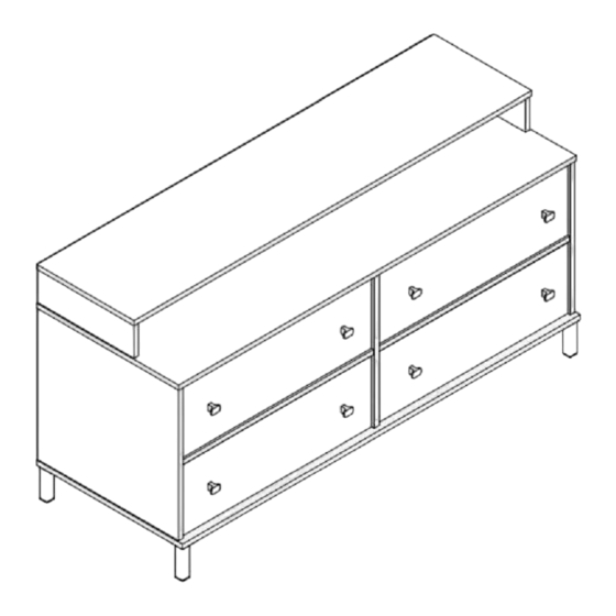
4566850COMS
Media Dresser
Date of Purchase_ L L
Lot Number:
THIS INSTRUCTION BOOKLET CONTAINS IMPORTANT SAFETY INFORMATION. PLEASE READ AND KEEP FOR FUTURE REFERENCE.
Do Not Return This Product!
Contact our customer service team for help first
1-800-489-3351
Visit: www.ameriwoodhome.com
A
WARNING
-Unit can tip over causing severe injury or death.
-Anchor unitto stud in wall (if instructed to)
-Do not albw children climb on unit
-Put heavy items on lower shelves or drawers
(Gray
Oak)
Aneriwood·
B344566xxxCOMS00AL
Easy
Tough
Assembly Difficulty Meter
Follow Ameriwood Home
HOME
Advertisement

Subscribe to Our Youtube Channel
Related Manuals for Ameriwood HOME 4566850COMS


Summary of Contents for Ameriwood HOME 4566850COMS
- Page 1 Easy Tough Assembly Difficulty Meter WARNING Follow Ameriwood Home -Unit can tip over causing severe injury or death. -Anchor unitto stud in wall (if instructed to) -Do not albw children climb on unit -Put heavy items on lower shelves or drawers...
- Page 5 Board Identification Not actual size Bottom Panel Top Panel Upper Drawer Top Upper Left/Right panel Upper Partition Right Side Panel 2PCS Left Side Panel Drawer Front Partition Panel Drawer Left Side Brace Panel 4PCS 4PCS 2PCS Drawer Support Drawer Bottom Drawer Back 4PCS Drawer Right Side...
- Page 6 Board Identification Not actual size FRONT VIEW DRAWER TOP DRAWER BACK BACK VIEW ameriwoodhome.com...
- Page 7 Each part has a unique part number. Please refer to the appropriate part number when ..contacting customer service for replacement parts. Before throwing any packaging, please verify all contents and make sure you have received all ..the parts listed above. 4566850COMS LABEL PART NAME Quantity...
- Page 8 Aneriwood· HOME Part List Not actual size (x12) ( x8) (x16) Cam Lock Cover (x8) (x8) Wood Dowel Minifix Housing Minifix Bolt Drawer Bracket <p6 x 30 mm <p15 x 10 mm <p7 x 34 mm (x 1 5) (x32) (x16 ) (x5) P/H Tapping Screw...
- Page 9 Each part has a unique part number. Please refer to the appropriate part number when � contacting customer service for replacement parts. Before throwing any packaging, please verify all contents and make sure you have received all � the parts listed above. 4566850COMS MODEL# (Gray Oak) Hardware Bag Reference #: 24566850COMS0AL ameriwoodhome.com...
- Page 10 STEP 1 Dowels extend out 3/8''. For more details,please see page 4 - Install Minifix Housing (3) and Wood Dowel (4) into Brace (I) as below shown. - Repeat this step for another Brace (I). Arrow facing outward (x2) ameriwoodhome.com...
- Page 11 STEP 2 - Install Minifix Bolt (2) and Wood Dowel (4) into Le� Side Panel (F) and Right Side Panel (G) as shown below. ameriwoodhome.com...
- Page 12 STEP 3 - Install Minifix Bolt (2) both side and Wood Dowel (4) into Par��on (H) as shown below. ameriwoodhome.com...
- Page 13 STEP 4 Quick Assembly Recomm. 2 Persons Proper Oriental of CAM LOCK - With another help to hold, Assemble Le� Side Panel (F), Par��on (H) with Brace (I) as show below. -Assemble Par��on (H), Right Side Panel (G) with Brace (I) as show below. unfinished edge unfinished edge unfinished edge...
- Page 14 STEP 5 Recomm. 2 Persons - Assemble Le� Side Panel (F), Par��on (H) and Right Side Panel (G) into Bo�om Panel (C) as show below. Turn the switch to lock. pre-drill nut turn switch to lock unfinished edge ameriwoodhome.com...
- Page 15 STEP 6 - Install Metal Leg(8) with Leg Screw (9) into Bo�om Panel (C) as shown. (x3) (x3) (x3) (x3) (x3) ameriwoodhome.com...
- Page 16 STEP 7 - Select one of the borings, install Safety Bracket Kit (12a) and (12b) into Top Panel (B) as shown below. **do not fully �ghten this screw ameriwoodhome.com...
- Page 17 STEP 8 - Assemble Top Panel (B) with Le� Side Panel (F), Par��on (H) and Right Side Panel (G) as shown below. Turn the switch to lock. pre-drill nut turn switch to lock unfinished edge ameriwoodhome.com...
- Page 18 STEP 9 - Assemble Upper Le�/Right Panel (D) and Upper Par��on (E) with Top Panel (B) as shown below. Turn the switch to lock. pre-drill nut unfinished edge turn switch to lock unfinished edge unfinished edge ameriwoodhome.com...
- Page 19 STEP 10 - Assemble Upper Top Panel (A) with Upper Le� / Right Panel (D) and Upper Par��on (E) as shown below. Turn the switch to lock. pre-drill nut turn switch to lock unfinished edge ameriwoodhome.com...
- Page 20 STEP 11 IMPORTANT! THE BACK PANEL IS A STRUCTURAL PART OF THIS UNIT AND MUST BE INSTALLED PROPERLY. With the help of another, carefully turn your unit over on its front side. Make sure the unit is square. Posi�on both back panel as shown. Using Nail (11), a�ached Bo�om Back Panel (Q) as shown below. Align the Bo�om Back Panel equally with outside edges and nails straight throught into back edges as shown.
- Page 21 STEP 12 IMPORTANT! THE BACK PANEL IS A STRUCTURAL PART OF THIS UNIT AND MUST BE INSTALLED PROPERLY. With the help of another, carefully turn your unit over on its front side. Make sure the unit is square. Posi�on both back panel as shown. Using Nail (11), a�ached Bo�om Back Panel (Q) as shown below. Align the Bo�om Back Panel equally with outside edges and nails straight throught into back edges as shown.
- Page 22 STEP 13 IMPORTANT! THE BACK PANEL IS A STRUCTURAL PART OF THIS UNIT AND MUST BE INSTALLED PROPERLY. With the help of another, carefully turn your unit over on its front side. Make sure the unit is square. Posi�on both back panel as shown. Using Nail (11), a�ached Upper Back Panel (P) as shown below. Align the Bo�om Back Panel and Upper Back Panel equally with outside edges and nails straight throught into back edges as shown.
- Page 23 STEP 14 IMPORTANT! THE BACK PANEL IS A STRUCTURAL PART OF THIS UNIT AND MUST BE INSTALLED PROPERLY. With the help of another, carefully turn your unit over on its front side. Make sure the unit is square. Posi�on both back panel as shown. Using Nail (11), a�ached Upper Back Panel (P) as shown below. Align the Bo�om Back Panel and Upper Back Panel equally with outside edges and nails straight throught into back edges as shown.
- Page 24 STEP 15 - Flip the unit, turn to front of unit. TURN 90° TURN 180° ameriwoodhome.com...
- Page 25 STEP 16 - Install Cam Lock Cover (1) . close to lock ameriwoodhome.com...
- Page 26 STEP 17 Tips for moving this unit: Two people should hold the unit and carry it from the bottom. It is recommended the drawers are not installed before moving. Improper movement beyong this could cause unit damage, instability, product collapse and serious injury.
- Page 27 STEP 18 For Masonry, Concrete, or other wall materials: Consult your local hardware store for appropriate anchors to securely attach the safety bracket. IMPORTANT: THIS UNIT MUST BE hole SECURE TO THE WALL TO HELP stud PREVENT TIPOVER. FOLLOW THESE INSTRUCTIONS TO INSTALL THE ANTI-TIPPING SAFETY BRACKET PROVIDED WITH THIS...
- Page 28 STEP 19 - Install Drawer Bracket (5) to Drawer Front (J) using PWA Screw (6). - Install Wood Dowel (4) into Drawer Support (O). - Repeat this step for other drawers. Arrow facing outward (x4) (x4) ameriwoodhome.com...
- Page 29 STEP 20 - Assemble Drawer Side (K & L) and Drawer Support (O) to Drawer Front (J). - Repeat this step for other drawers. unfinished surface (x4) ameriwoodhome.com...
- Page 30 STEP 21 - Slide in Drawer Bo�om (M) into Drawer Side (K & L) and Drawer Front (J). - Install Drawer Back (N) using Drive Fastener (7). - Install T Knob Handle Set (10a & 10b) to Drawer Front (J). - Repeat this for other drawers.
- Page 31 STEP 22 - Flip the unit, turn to front of unit. Repeat this for other drawers. TURN 90° (x4) ameriwoodhome.com...
- Page 32 STEP 23 - Install drawer into body. NOTE: The drawer bracket holes are slo�ed. Drawer fronts can be adjusted by loosening screw,making needed adjustments and re�ghtening screw. ameriwoodhome.com...
- Page 33 Maximum Loads This unit has been designed to support the maximum loads shown. Exceeding these load limits could cause sagging instability product collapse and/or serious injury. 25 lbs 25 lbs 11.3 kg 11.3 kg (each dra wer) 25 lbs 11.3 kg (each drawer) Cer cate of Conformity 1.
- Page 35 - Antes de la instalación, asegúrese de que el interruptor de luz esté desbloqueado. Sistema de cierre Cam Lock (página 3) Este sistema de sujeción Cam Lock se utilizará durante todo el proceso de montaje. ** Si la posición del pasador está desplazada, use pinzas para sostener el interruptor basculante en posición vertical y gire con cuidado el interruptor de bloqueoal centro de la abertura.
- Page 36 Página 7 - Instale la carcasa Minifix (3) y el pasador de madera (4) en el soporte (I) como se muestra a continuación. - Repita este paso para otro Brace (I). Página 8 - Instale el perno Minifix (2) y la espiga de madera (4) en el panel lateral izquierdo (F) y el lateral derecho Panel (G) como se muestra a continuación.
- Page 37 Página 15 - Ensamble el Panel Superior Izquierdo/Derecho (D) y la Partición Superior (E) con el Panel Superior (B) Como se muestra abajo. Gire el interruptor para bloquear. Página 16 - Ensamble el Panel Superior Superior (A) con el Panel Superior Izquierdo/Derecho (D) y el Panel Superior Partición (E) como se muestra a continuación.
- Page 38 Página 20 Con la ayuda de otro, voltee cuidadosamente su unidad sobre su lado frontal. Asegúrese de que la unidad sea cuadrada. Coloque ambos paneles traseros como se muestra. Usando el Clavo (11), fije el Panel Posterior Inferior (Q) como se muestra a continuación. Alinee el panel trasero inferior por igual con los bordes exteriores y clave directamente en los bordes traseros como se muestra.
- Page 39 Página 25 - Instale el soporte del cajón (5) en el frente del cajón (J) con el tornillo PWA (6). - Instale el pasador de madera (4) en el soporte del cajón (O). - Repita este paso para otros cajones. Página 26 - Ensamble el lateral del cajón (K y L) y el soporte del cajón (O) en el frente del cajón (J).
- Page 40 Página 30 Página 31...
- Page 41 -Avant l'installation, assurez-vous que l'interrupteur d'éclairage est déverrouillé. ** Si la position de la broche est décalée, utilisez une pince tenir l'interrupteur à bascule en position verticale position et tournez prudemment le verrou au centre de l'ouverture.
- Page 42 Page 7 - Installez le boîtier Minifix (3) et le goujon en bois (4) dans le renfort (I) comme illustré ci-dessous. - Répétez cette étape pour un autre croisillon (I). Page 8 - Installez le boulon Minifix (2) et le goujon en bois (4) dans le panneau latéral gauche (F) et le côté...
- Page 43 Page 15 - Assemblez le panneau supérieur gauche/droit (D) et la cloison supérieure (E) avec le panneau supérieur (B) comme indiqué ci-dessous. Tournez le commutateur pour verrouiller. Page 16 - Assemblez le panneau supérieur supérieur (A) avec le panneau supérieur gauche/droit (D) et le Partition (E) comme indiqué...
- Page 44 Page 20 IMPORTANT! LE PANNEAU ARRIÈRE EST UNE PARTIE STRUCTURELLE DE CET APPAREIL ET DOIT ÊTRE INSTALLÉ CORRECTEMENT A l'aide d'un autre, retournez délicatement votre appareil sur sa face avant. Assurez-vous que l'unité est carrée. Positionnez les deux panneaux arrière comme indiqué. À l'aide d'un clou (11), fixez le panneau arrière supérieur (P) comme illustré...
- Page 45 Page 25 - Installez le support de tiroir (5) sur l'avant du tiroir (J) à l'aide de la vis PWA (6). - Installez le goujon en bois (4) dans le support de tiroir (O). - Répétez cette étape pour les autres tiroirs. Page 26 - Assemblez le côté...
- Page 46 Page 27 - Faites glisser le bas du tiroir (M) dans le côté du tiroir (K et L) et l'avant du tiroir (J). - Installez l'arrière du tiroir (N) à l'aide de la fixation d'entraînement (7). - Installez l'ensemble de poignées à bouton en T (10a et 10b) sur l'avant du tiroir (J). - Répétez cette opération pour les autres tiroirs.
Need help?
Do you have a question about the 4566850COMS and is the answer not in the manual?
Questions and answers