Advertisement
Quick Links
Advertisement

Related Manuals for Launch MIG 218 XP

Summary of Contents for Launch MIG 218 XP
- Page 1 OPERATING MANUAL...
- Page 2 SAFETY RULES These general safety norms cover both arc welding machines and plasma cutting machines unless otherwise noted. The equipment must only be used for the purpose it was designed for. Using it in any other way could result in damage or injury and in breach of the safety rules. Only suitably trained and competent persons should use the equipment.
- Page 3 Do not weld on coated metals, unless the coating is removed from the weld area, the area is well ventilated, and while wearing an air-supplied respirator. The coatings on many metals can give off toxic fumes if welded. Prevention against burns and radiation Arc rays from the welding process produce intense, visible and invisible (ultraviolet and infrared) rays that can burn eyes and skin.
- Page 4 must be carefully cleaned before they can be cut/welded. Always allow the cut/welded material to cool before touching it or placing it in contact with combustible or flammable material. Do not work in atmospheres with high concentrations of combustible fumes, flammable gases and dust.
- Page 5 that has reached its end of life must be collected separately and returned to an environmentally compatible recycling facility. Handling of Compressed gas cylinders and regulators All cylinders and pressure regulators used in welding operations should be handled with care. Never allow the electrode, electrode holder or any other electrically “hot” parts to touch a cylinder.
- Page 6 CONTENTS 1. Preface 1.1 General 1.2 Introduction 1.3 Technical Specifications 1.4 Overview of Machine 2. InstallationI 3. Operation 4. Trouble shooting 5. Maintenance 5.1 Cables 5.2 Power source 5.3 Regular maintenance...
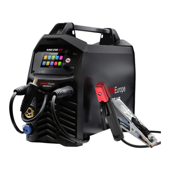
- Page 7 1.2 Introduction The Mig 218 XP power source is a generation of inverter-based portable MIG/MMA/TIG Welding machine with Synergic Programs for solid welding wires. It is a Multi-process power source designed for demanding professional use in Steels, Stainless, Cast Iron, Bronze, Aluminum welding.
- Page 8 Spool gun interface ■ Internal wire feeder, gear driven for up to 200mm Ø spool 1.3 Technical Specifications Power Supply / Phases (V-Ph) Mig 218 XP Duty Cycle@40°c AC230V±15% 50/60HZ 20% @ 200 Amps MIG 35%@200 Amps TIG Output Current Range MIG...
- Page 9 Power factor 8 KVA I Max MIG 35.2 Amps 26.5 Amps I eff MIG TIG 33.5 Amps 15.7 Amps Wire Feeder Type 15.7 Amps Protection Class 15 Amps Insulation Class Gear Driven 2 Roll Dimensions Power Source (LxWxH) IP 21S Weight Power Source Dimension 540 x 195 x 380 mm...
- Page 10 Voltage (Arc Length) / Inching Knob (Push) Negative output“-” Polarity changeover cable Rear View 10. Power switch 11. Input cable 12. Gas inlet Inside View 13. Spool Hub 14. Standard /Spool gun Switch 15. Wire Feed Assembly...
- Page 11 Control Panel Menu Navigation( Rotate and push to select menu option) Current (Wire feed speed) selection (Default) Return/Home button (long push) Voltage selection/Wire inch(Push) Main Menu Synergic MIG Steel Welding Synergic MIG Stainless Steel Welding Synergic MIG Aluminum Welding Manual MIG Welding TIG Welding MMA welding Information...
- Page 12 Synergic MIG Mode Current Thickness Voltage Arc length Wire Diameter Material/Gas Welding Process Trigger Mode More set up 10. Selection Dialogue Information Manual MIG Mode Current Voltage Trigger Mode More set up Selection Dialogue Information...
- Page 13 TIG Mode Current Voltage Selection Dialogue Info MMA Mode Current Voltage VRD(Optional) Hot Start Arc Force Electrode Type(Optional) Selection dialogue info...
- Page 14 Setting Unit Language Software Information Factory Reset Selection Dialogue info...
- Page 15 Icon Reference Guide Synergic MIG Steel Welding Burn Back time Synergic MIG Stainless Steel Welding Preflow time Synergic MIG Aluminum Welding Postflow time Manual MIG Welding Inductance TIG Welding Creep Start MMA Welding 2 Step Machine Information 4 Step Setting Special 2 Step Wire Diameter Special 4 Step...
- Page 16 DC Welding Continuous Spot OFF Time Single Pulse Welding Wire feeding Speed Double Pulse Welding More Setting Fast MIG Welding VRD (Voltage Reduction Device) 16,5 Synergic DC Fast Welding Hot Start Synergic Pulse Fast Welding Arc Force Synergic Double Pulse Fast Electrode Type Welding Synergic Cold Fast Welding...
- Page 17 INSTALLATION Unpacking Check the packaging for any signs of damage. Carefully remove the machine and retain the packaging until the installation is complete. Location The machine should be located in a suitable position and environment. Care should be taken to avoid moisture, dust, steam, oil or corrosive gases Place on a secure level surface and ensure that there is adequate clearance around the machine to ensure natural airflow.
- Page 18 MIG Welding Insert the welding torch into the “Euro connector for torch in MIG” output socket on the front panel of the machine, and tighten it. Install the wire spool on the spindle adapter. Connect the cylinder equipped with the gas regulator to the gas inlet on the back panel of the machine with a gas hose.
- Page 19 Gas less Self Shielded Welding Insert the welding torch into the “Euro connector for torch in MIG” output socket on the front panel of the machine, and tighten it. Insert the cable plug with work clamp into the “+” output terminal on the front panel of the welding machine, and tighten it clockwise.
- Page 20 TIG Welding For the TIG torch with Dinse connection ■ Insert the cable plug with the earth clamp into the “+” socket on the front panel of the welding machine, and tighten it clockwise. ■ Insert the cables plug of the TIG torch into the “-” socket on the front panel of the machine or insert the Europe plug of the TIG torch into the Europe socket(for the torch with Europe connector) and tighten clockwise.
- Page 21 OPERATION Before starting any welding activity ensure that you have suitable eye protection and protective clothing. Also take the necessary steps to protect any persons within the area. MIG/MAG Connect the MIG torch leads as detailed above. Ensure that a suitable inert gas supply is connected.
- Page 22 Where required adjust the burn-back time potentiometer (above the feed unit inside the machine) to get the proper electrode stick-out. One second after the arc stops, the gas supply will be cut off. Gas selection Metal inert gas welding (MIG): Uses Argon (Ar), Helium (He) or Ar-He mixtures as the shield gas, and it mainly used for welding aluminium and its alloys.
- Page 23 should be 10 times as the welding wire diameter. Shield gas flow selection The protection effect is the primary consideration. Besides, the protection effect of inner-angle welding is better than that of external-angel welding, so the gas flow in inner-angle welding should be lower. Less or no shield gas is needed in FCAW. Refer to the table below for the recommended gas flow rates.
- Page 24 TROUBLE SHOOTING In the event of a failure of the machine, contact an authorised service agent. The following operation requires sufficient professional knowledge on electric aspects and comprehensive safety knowledge. Make sure the input cable of the machine is disconnected from the electricity supply and wait for 5 minutes before removing the machine covers Before taking your unit for servicing, check the list below.
- Page 25 Welding can be carried out when pushing the torch trigger, but the voltage cannot be adjusted. Check if the voltage feedback wire inside the machine is in good condition.! PCB inside the machine may be defective. Welding current is unstable. Check the pressure arm on the wire feeder for proper pressure.! Check if the drive roll matches the wire size being used.! Check the contact tip of the welding torch for wear.
- Page 26 MAINTENANCE The utilisation level of the power source and its working environment should be taken into consideration in planning the frequency of maintenance of the machine. Appropriate use and preventive maintenance guarantee the trouble-freest use of the equipment. This allows you to avoid interruptions in use and increases the productivity of the machine.
- Page 27 ■ Checking of electrical connections. ■ Checking of the mains cable and plug. ■ Replacement of damaged or worn parts. ■ Calibration testing, with adjustment of the functions and operational values of the machine, if necessary.
- Page 28 LAUNCH Europe GmbH Heinrich-Hertz-Str. 10 ▪ 50170 Kerpen Tel.: +49 22 73 9875-0 ▪ Fax: +49 22 73 9875-33 info@launch-europe.de ▪ www.launch-europe.de...
Need help?
Do you have a question about the MIG 218 XP and is the answer not in the manual?
Questions and answers