
Summary of Contents for DRESSTA 515G
- Page 1 SM515G520G06/1E SERVICE MANUAL 515G 520G SERIAL NUMBER 93501 SERIAL NUMBER 83501 AND UP AND UP DRESSTA www.l-34.com - запчасти Dressta...
- Page 2 - запчасти Dressta...
- Page 3 THIS MATERIAL IS PROPRIETARY TO DRESSTA Co. Ltd. AND NOT TO BE REPRODUCED, USED, OR DISCLOSED EXCERT IN ACCORDANCE WITH WRITTEN AUTHORIZATION FROM DRESSTA Co. Ltd. IT IS OUR POLICY TO IMPROVE OUR PRODUCTS WHENEVER IT IS POSSIBLE AND PRACTICAL TO DO SO.
- Page 4 - запчасти Dressta...
- Page 5 SECTION 1 INTRODUCTION www.l-34.com - запчасти Dressta...
- Page 6 - запчасти Dressta...
- Page 7 DANGER! This symbol and text in bold letters is used throughout this Manual indicates an emergency, which is not avoided may result in injury or death. This sign calls your attention to a most serious danger. DRESSTA 515G-520G www.l-34.com - запчасти Dressta...
- Page 8 2. Be sure the machine has the correct equipment required by local rules and regulations. 3. A rollover protective structure ROPS with a seat belt and falling objects protective structure FOPS are required in almost all applications. DO NOT operate this machine without a ROPS-FOPS cab. 515G-520G DRESSTA www.l-34.com - запчасти Dressta...
- Page 9 9. Safety must always be the operator's most important concern. He must refuse to operate when he knows it is unsafe and consult his supervisor when safety is in doubt. DRESSTA 515G-520G www.l-34.com - запчасти Dressta...
- Page 10 5. Turn on the machine's lights at night and times of poor visibility to see and be seen. 6. DO NOT adjust the seat while the machine is moving because a loss of control may result. Stop the machine, apply the parking brake and then adjust the seat. 515G-520G DRESSTA www.l-34.com - запчасти Dressta...
- Page 11 15. Keep the machine as close to the side of the road as safely possible to leave room for oncoming and passing vehicles. 16. Pass other vehicles only when the road is clear and the machine has enough distance and reserve power to pass. DRESSTA 515G-520G www.l-34.com - запчасти Dressta...
- Page 12 STAND CLEAR. DO NOT PULL OR TOW UNLESS THE OPERATOR'S COMPARTMENT IS GUARDED AGAINST OR OUT OF REACH OF A WHIPPING CHAIN OR CABLE. 515G-520G DRESSTA www.l-34.com - запчасти Dressta...
- Page 13 14. Use only approved parts specified in PARTS CATALOG for repairs and maintenance. Failure to do so could compromise personal safety, machine performance and reliability. DRESSTA 515G-520G www.l-34.com - запчасти Dressta...
- Page 14 15. Never align holes with fingers or hands. Use the proper aligning tool to avoid injury. 16. Remove sharp edges and burrs from reworked parts. 17. Do not carry loose objects in pockets because they might catch on the machine and result in a fall or injury. 515G-520G DRESSTA www.l-34.com - запчасти Dressta...
- Page 15 ONLY after the pressure is relieved. 2. Use extreme caution when adding coolant to a hot radiator to avoid being burned. Wear gloves and goggles and keep face away from the filler neck. DRESSTA 515G-520G www.l-34.com - запчасти Dressta...
- Page 16 Keep the fluid containers out of the reach of children. NEVER puncture the fluid container or put it into a fire. Dispose of empty containers properly. DO NOT store fluid containers in the operator's compartment. 515G-520G DRESSTA www.l-34.com - запчасти Dressta...
- Page 17 2740 [mm] 2820 [mm] Reach at maximum height and 45° dump angle per SAE* 1040 [mm] 1020 [mm] Maximum Lifting Height 4600 [mm] 5050 [mm] Weight 9500 [kg] 11000 [kg] may vary depending on wheel size. DRESSTA 515G-520G www.l-34.com - запчасти Dressta...
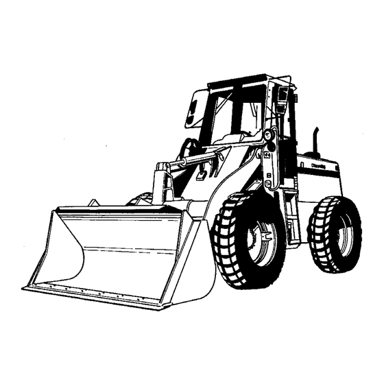
- Page 18 515G with a Bucket of 1.53 [m 520G with a Bucket of 1.91 [m Fig. 1.2. General Dimensions for the standard configuration of 515G, 520G wheel loaders equipped with ROPS-FOPS cab, standard bucket with cutting edge and standard tires 515G-520G DRESSTA www.l-34.com - запчасти...
- Page 19 Stamped Machine Serial Number (3), is located on the LH side of the rear frame. Fig. 1.3. Location of Machine and ROPS-FOPS Cab Serial Numbers Plates 1. ROPS-FOPS Serial Number Plate 2. Machine Serial Number Plate 3. Stamped Machine Serial Number DRESSTA 515G-520G www.l-34.com - запчасти Dressta...
- Page 20 Parts Checklist No (CPL) (2), Engine Model (3) and Rated HP and RPM (4) Fig. 1.5. Engine Serial Number Plate 1. Engine No 3. Engine Model 2. Parts Checklist No (CPL) 4. Rated HP and RPM 515G-520G DRESSTA www.l-34.com - запчасти Dressta...
- Page 21 Check splines with their mating parts for wear. Check gears and splines for pitting, burrs, broken or missing teeth. Burrs can be removed with a fine carborundum stone, but care must be taken so that only the burr is removed, and that the gear or spline profile is not changed. DRESSTA 515G-520G www.l-34.com - запчасти Dressta...
- Page 22 (activator) to obtain maximum strength and cure speed at room temperature. Active Metals Inactive Metals Steel Stainless Steel Copper Nickel Brass Zinc Manganese Cadmium Bronze Pure Aluminum Titanium Bright Platings Aluminum Alloy Anodized Surface 515G-520G DRESSTA www.l-34.com - запчасти Dressta...
- Page 23 Loctite anaerobic adhesives and sealants. It is especially recommended for applications with passive metals or inert surfaces and with large bond gaps. DRESSTA 515G-520G www.l-34.com - запчасти Dressta...
- Page 24 (See Fig.1.7). A fast curing type primer will fix parts for normal handling in 10 to 15 minutes and will achieve 75 [ C] of ultimate strength in 1 hour and full cure in 2 to 4 hours. 515G-520G DRESSTA www.l-34.com - запчасти Dressta...
- Page 25 INTRODUCTION SECTION 1 Page 21 LOCTITE USAGE Cure Speed vs. Activator Cure Speed vs. Substrate Cure Speed vs. Temperature Fig. 1.7. Typical Curing Performance DRESSTA 515G-520G www.l-34.com - запчасти Dressta...
- Page 26 0.75 - when parkerized (phosphate coated) bolts or nuts are used. 0.85 - when cadmium plated bolts or nuts and zinc bolts w/waxed zinc nuts are used. 0.90 - when hardened surfaces are used under the nut or bolt head. 515G-520G DRESSTA www.l-34.com - запчасти Dressta...
- Page 27 Metric Thread alloy or low carbon boron steel quenched and tempered. Class 10.9 Marked on top or side of head. Medium carbon or carbon Metric Thread alloy or low carbon boron steel quenched and tempered. DRESSTA 515G-520G www.l-34.com - запчасти Dressta...
- Page 28 (Rockwell "C" 38 45), all phosphate coated and assembled without supplemental lubrication (as received) condition. Phosphate coated bolts used in tapped holes in steel or gray iron and phosphate coated bolts used with phosphate coated prevailing torque nuts. 515G-520G DRESSTA www.l-34.com - запчасти Dressta...
- Page 29 47 61 1 – 1/2 1/ 2 62 79 1/ 2 75 88 2 – 1/2 1/ 2 107 123 187 203 3 – 1/2 159 180 Inside diameter of hydraulic tube or hose fitting. DRESSTA 515G-520G www.l-34.com - запчасти Dressta...
- Page 30 6.2 7.3 Worm Drive - 1-3/4 inch 2.2 3.3 4.5 5.6 Open Diameter and Under Worm Drive - Over 1-3/4 inch Open Diameter — 4.5 5.6 Worm Drive - All "Ultra-Tite" 10.7 11.8 4.5 5.6 515G-520G DRESSTA www.l-34.com - запчасти Dressta...
- Page 31 21. TORQUE VALUES FOR AIR CONDITIONING O-RING CONNECTIONS Size Torque Values for Materials [Nm] Connection Thread [inch] Steel-steel 7/16-20 15 25 5/8-18 27 33 3/4-16 40 48 7/8-14 47 54 1-1/16-12 54 61 1-1/16-14 54 61 DRESSTA 515G-520G www.l-34.com - запчасти Dressta...
- Page 32 18. Torque Values for Hydraulic Tubes and Fittings ..............25 19. Torque Values for Hose Clamps .................... 26 20. Torque Values for Air Conditioning Tubes and Fittings............26 21. Torque Values for Air Conditioning O-ring Connections ............26 DRESSTA 515G-520G www.l-34.com - запчасти Dressta...
- Page 33 SECTION 4 BRAKES www.l-34.com - запчасти Dressta...
- Page 34 - запчасти Dressta...
- Page 35 19. Description and Operation......................17 20. Specification ..........................19 21. Removal ............................ 19 22. Disassembly ..........................20 23. Inspection and Repair ....................... 20 24. Reassembly..........................21 25. Installation ..........................22 DIFFERENTIAL VALVE 26. Description and Operation......................22 DRESSTA 515G-520G www.l-34.com - запчасти Dressta...
- Page 36 - запчасти Dressta...
- Page 37 2. Differential Valve 7. Parking Brake 3. Pressure Differential Switch 8. Front Brake Line 4. Brake Pump 9. Rear Brake Line 5. Brake Pump Booster (only for 520G) Fig. 4.1. 515G Machine Braking System DRESSTA 515G-520G www.l-34.com - запчасти Dressta...
- Page 38 MASTER BRAKES Fig. 4.2. 520G Machine Braking System Only for 515G: When either of two brake pedals (6, Fig. 4.1) is depressed the brake linkage will move a spool in the brake pump (4). Only for 520G: When either of two brake pedals (6, Fig. 4.2) is depressed the brake linkage will move a spool in the brake pump booster (5).
- Page 39 Brake disc ......... Steel bonded with friction material; sides must be parallel within 0.10 [mm] and flat within 0.25 [mm]. Minimal brake disc lining thickness ................0.7 [mm] Gap between cab floor and pedal arm pad (520G only) ..........2 ±1 [mm] DRESSTA 515G-520G www.l-34.com - запчасти Dressta...
- Page 40 2. Fully depress and hold the brake pedal. Be sure the parking brake is released. WARNING! Be sure the area in front of the machine is clear of personnel and obstructions because the machine may move forward during this test. 515G-520G DRESSTA www.l-34.com - запчасти Dressta...
- Page 41 5. Pressure the brake to 6 [MPa] and close the valve (2). Observe drop pressure after 5 minutes. 6. The maximum pressure drop is 0.1 [MPa] within 5 minutes. If pressure drop is bigger than maximum, replace brake piston seal rings or bearing retainer seal ring. DRESSTA 515G-520G www.l-34.com - запчасти Dressta...
- Page 42 NOTE: It is necessary to remove the complete axle in order to service the front axle brakes. Only the axle shaft assemblies need to be removed for rear axle brake service. Fig. 4.5. Service Brake (only 515G) Fig. 4.6. Service Brake (only 520G) 1.
- Page 43 Fig. 4.9. Removing the Brake Plate Fig. 4.10. Removing the Brake Piston 1. Brake Plate 3. Bearing Retainer 1. Slotted Screws 3. Brake Piston 2. Brake Piston 4. Drive Axle Shaft Housing 2. Screwdriver DRESSTA 515G-520G www.l-34.com - запчасти Dressta...
- Page 44 1. Install the new O-ring (1, Fig.4.12) on the brake piston (2). 2. Replace the bearing retainer O-ring (1, Fig. 4.13). NOTE: Before installing the brake piston, thoroughly lubricate the piston O-ring and bearing retainer O-ring with oil. 515G-520G DRESSTA www.l-34.com - запчасти Dressta...
- Page 45 3. Position the brake piston in the brake piston cavity making sure that the three tapped holes (2, Fig. 4.14) are facing outward. 4. Only for 515G: Install special tool 21.261.0153 (1, Fig. 4.15) using four of the bolts (2) used for mounting the axle shaft housing assy (6, Fig. 4.5) to differential housing (7).
- Page 46 Adjust the clevis to take up all of the slack in the control cable. After that repeat steps 1 5. 7. If further adjustment is impossible and parking brake does not hold the machine stationary, check the parking brake condition. Refer to INSPECTION AND REPAIR under PARKING BRAKE in this section. 515G-520G DRESSTA www.l-34.com - запчасти Dressta...
- Page 47 2. Parking Brake 8. Yoke 25. Washer 39. Bolt 3. Brake/Lever Housing Assy 9. Washer 26. Springs 40. Bolt 4. Brake Shoe Assy 20. Brake Drum 33. O-ring 7. Retainer 21. Brake Cross Lever 36. Bolt DRESSTA 515G-520G www.l-34.com - запчасти Dressta...
- Page 48 Only for 515G: When the brake pedal is pushed, the brake arm assy pushes piston assy (9) in. Only for 520G: When the brake pedal is pushed, the brake arm assy pushes piston of the brake pump booster.
- Page 49 22. O-ring 5. Gasket 14. Cup 23. Piston 6. Gauges 15. Piston 24. Housing 7. Gasket 16. Piston Assy 25. O-ring 8. Snap Ring 17. Spring 26. Connector 9. Piston Assy 18. Guard 27. Connector DRESSTA 515G-520G www.l-34.com - запчасти Dressta...
- Page 50 1. Disconnect and drain the front and the rear brake circuit lines (3 and 4, Fig. 4.18 and Fig. 4.19) from the brake pump (1). 2. Only for 515G: Remove two bolts (2) securing the brake pump (1) to the front frame and remove the brake pump (1).
- Page 51 2. Install the snap ring (8) in the housing bore to retain the piston. 3. Install gasket (5) and plug (4) into the bottom of the housing (24). 4. Only for 515G: Place brake pump (1, Fig. 4.18) against front frame bracket and install the two bolts (2).
- Page 52 Should the transmission hydraulics be lost, the brake system will still operate only without a hydraulic assist. When the pedal is depressed, the signal spool (1) will mechanically contact the piston (5) and actuate the brake pump. 515G-520G DRESSTA www.l-34.com - запчасти Dressta...
- Page 53 (N), the electrical system master switch is off and the keys are removed from master switch and from starting switch. WARNING! Always lock the frames together before working near the center of the machine. If the frames move, serious injury or death could result. DRESSTA 515G-520G www.l-34.com - запчасти Dressta...
- Page 54 7. Unscrew the plug (19) with O-ring (18) and remove parts (18, 25, 26, 27, 28, 29, 30, 31 and 32) from housing (1). 8. Remove the plugs (20). 23. INSPECTION AND REPAIR Fig. 4.21. Brake Pump Booster Exploded View 515G-520G DRESSTA www.l-34.com - запчасти Dressta...
- Page 55 4. Place the bolt (13) through the piston (12). Apply Loctite 242 to the first 2 3 threads on the bolt (13) and install the nut (14). Torque the nut to 147-166 [Nm]. Install the spring (15) on the bolt (13). DRESSTA 515G-520G www.l-34.com - запчасти Dressta...
- Page 56 The O-rings (8) located on each end of the spool (7) will prevent leakage when the switch (9) is removed. The switch (9) and the valve are serviced as a complete assembly. 515G-520G DRESSTA www.l-34.com - запчасти Dressta...
- Page 57 SECTION 4 Page 23 DIFFERENTIAL VALVE Fig. 4.22. Differential Valve 1. Spring 6. Spring 2. Terminal 7. Spool 3. Plunger 8. O-ring 4. Contact 9. Differential Pressure Switch 5. Brake Tube 10. Stop Lights Switch DRESSTA 515G-520G www.l-34.com - запчасти Dressta...
- Page 58 - запчасти Dressta...
- Page 59 SECTION 5 STEERING www.l-34.com - запчасти Dressta...
- Page 60 - запчасти Dressta...
- Page 61 STEERING SECTION 5 CONTENTS 1. Description..........................3 2. Specifications..........................4 3. Service Diagnosis ........................4 4. Removal............................5 5. Disassemble, Inspection, Repair and Reassemble ..............6 6. Installation........................... 7 DRESSTA 515G-520G www.l-34.com - запчасти Dressta...
- Page 62 - запчасти Dressta...
- Page 63 Articulated front and rear frames make possible left and right 40 articulation and 4.70[m] - (515G), 5.05[m] - (520G) turning radius outside of the tires. Generally the steering system consists of hydraulic components and mechanical linkage. Mechanical linkage of the steering system consists of the steering wheel (1) and steering column assy (2).
- Page 64 1. Steering column seized or dirt. 1. Clean, repair or replace steering column. 2. Telescope spring weak or broken. 2. Replace telescope spring. 3. Lever assy details failed or damaged. 3. Repair or replace lever assy. 515G-520G DRESSTA www.l-34.com - запчасти Dressta...
- Page 65 8. Remove four bolts with washers (6, Fig. 5.4) mounting steering column assy (7) lower flange to the operator platform bracket (4). Free steering column (4, Fig. 5.3) lower shaft splined end from the steering control valve (8) and take the steering column out of the machine. DRESSTA 515G-520G www.l-34.com - запчасти Dressta...
- Page 66 2. Referring to the diagnosis chart check for excessive wear or damage steering column assy components: - lever assy - catch assy (20) - springs set (10) - bearings (14 and 26) - steering column - (27) 515G-520G DRESSTA www.l-34.com - запчасти Dressta...
- Page 67 (4). 8. Install steering wheel (2, Fig. 5.3) onto steering column assy (4) shaft end. 9. Install steering wheel nut (2A) onto steering column assy (4) shaft end. Torque the nut to 48 [Nm]. DRESSTA 515G-520G www.l-34.com - запчасти Dressta...
- Page 68 14. Axial Bearing 23. Catch 6. Pitman Arm 15. Cover Assy 24. Pin 7. Lock Washer 16. Cover 25. Pin 8. Lever 17. Screw 26. Telescope Bearing 9. Handle 18. Clamp Strip 27. Steering Column 515G-520G DRESSTA www.l-34.com - запчасти Dressta...
- Page 69 SECTION 6 COOLING SYSTEM www.l-34.com - запчасти Dressta...
- Page 70 - запчасти Dressta...
- Page 71 10. INSTALLATION ............13 DRESSTA www.l-34.com - запчасти Dressta 515G-520G...
- Page 72 - запчасти Dressta...
- Page 73 The cooling system permits to operate at higher engine temperatures without risk of coolant boiling. Information on cooling system is contained in 515G, 520G Wheel Loaders Operator’s Manual and Operation and Maintenance Manual Industrial QSB-3.9-30, QSB4.5-30 and QSB-5.9-30 Series Engines, Bulletin No 4021388.
- Page 74 Heat is transferred away to atmosphere by air flowing through the radiator core. Then oil is directed to the return filter and oil reservoir. 515G-520G DRESSTA www.l-34.com - запчасти Dressta...
- Page 75 515G ........
- Page 76 Refer to SERVICE DIAGNOSIS - Section 7. External leakage of transmission oil 1. Damaged drive train system oil cooler. Remove drive train oil cooler. Conduct pressure test of oil cooler, remove leakages or replace. 515G-520G DRESSTA www.l-34.com - запчасти Dressta...
- Page 77 5. DESCRIPTION 515G – Radiators assy is hanged on two vertical brackets welded to side surface of transmission oil cooler and hydraulic oil cooler. Brackets are mounted to the radiator guard assy with bolts.
- Page 78 Remove gas spring on both sides. Attach slings and carefully lift the engine guards assy (3). Remove bolts securing lower cover (5) to frame and take it out of the frame. Fig. 6.3. Engine and Radiators Assy Guards 515G 1. Air Precleaner 4.
- Page 79 9. Loosen the clamp, remove coolant inlet tube (5). 10. Remove hose (6) from drive train oil cooler. Fig. 6.5. Radiators Assy Disassembly Points 515G / 520G (bottom view) 1. Engine Cooling System Drain Hose 2. Hydraulic System Oil Cooler Hose (inlet) Fig.
- Page 80 COOLING SYSTEM SECTION 6 Page 8 Fig. 6.7. A/C System Disassembly 515G 1. Fan Shroud 2. Bolts 16. MACHINES EQUIPPED WITH A/C SYSTEM: Loosen clamp, remove engine cooling system fill hose (2, Fig. 6.4). Remove bolts (2, Fig. 6.7) securing fan shroud (1) to radiator. Secure shroud with A/C system condenser on frame.
- Page 81 8. Disconnect plug from the coolant level switch (3). Remove wire harness from the strip and secure it out of the frame. 9. Loosen the clamp, remove engine cooling system venting hose (4). 10. Loosen the clamp, remove coolant inlet tube (5). DRESSTA 515G-520G www.l-34.com - запчасти Dressta...
- Page 82 15. Loosen the clamp (2, Fig. 6.11) remove hose (3) from elbow (1). 16. Remove hose (4, Fig. 6.11) from drive train oil cooler. 17. Remove radiator bar (5) from both sides of the radiator. 515G-520G DRESSTA www.l-34.com - запчасти Dressta...
- Page 83 NOTE: Elements (cores) of the radiator assy, are mounted (welded) and have to be replaced by new if unrepairable. NOTE: Elements (cores) of the radiator assy, are made of aluminum, any repairs required are to be done in experienced workshop. DRESSTA 515G-520G www.l-34.com - запчасти Dressta...
- Page 84 Fig. 6.12. Radiators Assy with Shroud 1. Hydraulic Oil Cooler 4. Engine Cooler 7. Plate Bottom 2. Bolts 5. Drive Train Oil Cooler 8. Overflow Hose 3. Radiator Cap 6. Fan Shroud 9. Rubber Seal 515G-520G DRESSTA www.l-34.com - запчасти Dressta...
- Page 85 (3) to hydraulic reservoir and radiators guards (4). Reinstall gas springs on both sides of the guards. Remove slings. 18. Install precleaner (1), and exhaust pipe (2). Close the engine guards. DRESSTA 515G-520G www.l-34.com - запчасти Dressta...
- Page 86 18. Attach slings to the engine guards assy (2, Fig. 6.9), lift and position guards assy, install the bolts fastening it to hydraulic reservoir and radiators guards (3). Reinstall gas springs on both sides of the guards. Remove slings. 19. Reinstall precleaner (1, Fig. 6.9). 515G-520G DRESSTA www.l-34.com - запчасти Dressta...
- Page 87 SECTION 7 DRIVE TRAIN www.l-34.com - запчасти Dressta...
- Page 88 - запчасти Dressta...
- Page 89 3. Hydraulic Oil Flow ........................3 4. Specifications ..........................4 5. Service Diagnosis ........................6 TESTS AND CHECKS 6. Checking the Charging Pump Flow Rate ..................8 7. Checking Transmission and Torque Converter Pressures ............8 8. Torque Converter Stall Speed Check ..................10 DRESSTA 515G-520G www.l-34.com - запчасти Dressta...
- Page 90 - запчасти Dressta...
- Page 91 Oil from the priority valve (8) is directed to the pressure regulator valve (10) and control valve (11). In machine 515G oil from the filter is directed to the pressure regulator valve (10) and control valve (11).
- Page 92 (285 480 [kPa] for 520G and 285 580 [kPa] for 515G) in the circuit, to allow oil to enter the lubrication circuit, where it joins the flow from the oil cooler. Lube oil is directed to lubricate all disengaged clutch packs. When the lube circuit is satisfied,...
- Page 93 15. Directional Spools M. Main Oil Pressure 7. Pressure Filter 16. Brake Pump Booster (520G only) R. Reverse Clutch Pack 8. Priority Valve (520G only) 17. Output Shaft 9. Oil Cooler 18. Torque Converter DRESSTA 515G-520G www.l-34.com - запчасти Dressta...
- Page 94 7. Torque converter oil pressure abnormal 7. Refer to CHECKING TRANSMISSION AND TORQUE CONVERTER PRESSURES in this Section. 8. Low oil flow through system 8. Refer to CHECKING CHARGING PUPM FLOW RATE in this Section. 515G-520G DRESSTA www.l-34.com - запчасти Dressta...
- Page 95 2. Check range pack pressures. Refer to CHECKING TRANSMISSION AND TORQUE CONVERTER PRESSURES in this Section. Knocking while travel changes 1. Drive shafts splines backlash 1. Replace worn or damaged parts 2. Transmission output shaft spline backlash 2. Repair transmission DRESSTA 515G-520G www.l-34.com - запчасти Dressta...
- Page 96 WARNING! Be sure the area in front and behind the machine is clear of personnel and obstructions as the machine may move during this test. DO NOT allow anyone near the tires or on the access ladders during the test. 515G-520G DRESSTA www.l-34.com - запчасти Dressta...
- Page 97 Forward Second 2050 2345 Forward third 2050 2345 Reverse first 2050 2345 Reverse second 2050 2345 Reverse third 2050 2345 4. If pressures do not meet specifications, refer to the following PRESSURE DIAGNOSTIC CHART. DRESSTA 515G-520G www.l-34.com - запчасти Dressta...
- Page 98 PRESSURE REGULATOR VALVE in Section 7C. Low or zero each directional and range engagement pressure 1. Low main oil pressure. 1. Refer to first complaint above. 2. Transmission disconnect switch 2. Refer to ELECTRICAL, Section 8 malfunction. 515G-520G DRESSTA www.l-34.com - запчасти Dressta...
- Page 99 2. Refer to CHECKING TRANSMISSION AND TORQUE CONVERTER PRESSURES in this Section. 3. Clutch pack excessive wear. 3. Refer to TRANSMISSION, Section 7C. Stall speed too low 1. Too low engine power. 1. Refer to ENGINE, Section 12. DRESSTA 515G-520G www.l-34.com - запчасти Dressta...
- Page 100 - запчасти Dressta...
- Page 101 SECTION 7B TORQUE CONVERTER www.l-34.com - запчасти Dressta...
- Page 102 - запчасти Dressta...
- Page 103 5. Service Diagnosis ........................6 6. Test and Adjustments ........................ 6 TORQUE CONVERTER 7. Removal ........................... 7 8. Disassembly ..........................7 9. Inspection and Repair ......................11 10. Reassembly ..........................11 11. Installation ..........................14 DRESSTA 515G-520G www.l-34.com - запчасти Dressta...
- Page 104 - запчасти Dressta...
- Page 105 SECTION 7C. Also covered in SECTION 7C is the procedure for checking the pressures in the transmission/converter circuit. DRESSTA 515G-520G www.l-34.com - запчасти Dressta...
- Page 106 21. Flat Washer 6. Impeller 14. Turbine 22. Front Cover 7. Ball Bearing 15. Drive Housing 23. Bolt 8. Drive Gear 16. Ball Bearing W/Retaining Ring 24. Flat Washer Fig. 7B.1. Cross Section of Torque Converter 515G-520G DRESSTA www.l-34.com - запчасти Dressta...
- Page 107 Fig. 7B.2. Exploded View of Torque Converter 4. SPECIFICATIONS Torque converter to transmission housing bolts..............92 [Nm] Impeller to drive housing bolts...................34 42 [Nm] Drive gear to impeller bolts....................34 42 [Nm] Front cover to drive housing bolts ..................19 23 [Nm] DRESSTA 515G-520G www.l-34.com - запчасти Dressta...
- Page 108 1. Coat all suction lines and connections with shaving cream. 2. Operate the machine in neutral and observe the shaving cream. 3. If a leak is present, a crater will form in the shaving cream at the location of the leak. 515G-520G DRESSTA www.l-34.com - запчасти Dressta...
- Page 109 5. Remove the retaining ring (18) that retains bearing (17) to drive housing (15). Separate the drive housing from turbine (14). 6. Remove retaining ring (19). Using a puller remove bearing (17) from the turbine as shown in Fig. 7B 6. DRESSTA 515G-520G www.l-34.com - запчасти Dressta...
- Page 110 7. Remove retaining ring (13), stator (12), retaining ring (13) and retaining ring (11) from the sleeve assy (1). 8. Remove bolts (9) and separate impeller (6) from drive gear (8). Fig. 7B.6. Removing Turbine Bearing 515G-520G DRESSTA www.l-34.com - запчасти Dressta...
- Page 111 13. Remove the bolt securing the drive gear bearing retainer. Refer to Fig. 7B.9. 14. Remove the drive gear as shown in Fig. 7B.10. Fig. 7B.9. Removing Bearing Retainer Bolt Fig. 7B.10. Removing Drive Gear DRESSTA 515G-520G www.l-34.com - запчасти Dressta...
- Page 112 2. Install drive gear (8) on the sleeve assy (1) as shown in Fig. 7B.13. 3. Install bearing (7). It is recommended that the bearing be heated to facilitate installation. Install retaining ring (11). Refer to Fig. 7B.14. 515G-520G DRESSTA www.l-34.com - запчасти Dressta...
- Page 113 (13), stator (12) and retaining ring (13) on the sleeve assy (1). 5. Remove the aligning dowels from the impeller (6). Install mounting hardware (9 and 10). Torque the bolts to 34 42 [Nm]. Fig. 7B.15. Aligning Dowels for Impeller Installation DRESSTA 515G-520G www.l-34.com - запчасти Dressta...
- Page 114 14. Using new O-rings install the converter charging pump and the double hydraulic supply pump. Torque the bolts to 34 42 [Nm]. 15. Install converter housing seal ring (1) Fig. 7B.12 and O-ring (2). 515G-520G DRESSTA www.l-34.com - запчасти Dressta...
- Page 115 3. Lubricate the clutch pack shaft seal rings with grease. 4. Install the sump strainer to converter charging pump tube. 5. Install the transmission assembly in the machine as described in SECTION 7C, "TRANSMISSION". DRESSTA 515G-520G www.l-34.com - запчасти Dressta...
- Page 116 - запчасти Dressta...
- Page 117 SECTION 7C TRANSMISSION www.l-34.com - запчасти Dressta...
- Page 118 - запчасти Dressta...
- Page 119 14. Inspection and Repair ....................... 30 15. Reassembly and Installation ..................... 30 TRANSMISSION CONTROL VALVE 16. Description ..........................31 17. Removal and Disassembly......................33 18. Inspection and Repair ....................... 34 19. Reassembly and Installation ..................... 35 DRESSTA 515G-520G www.l-34.com - запчасти Dressta...
- Page 120 - запчасти Dressta...
- Page 121 8. Input Shaft 21. Strainer 9. Reverse Idler Gear 22. Output shaft 10. Gear Range (1) Clutch 23. Yoke 11. Gear Range (1) Drum 24. Torque Converter Mounting Bolts 12. Gear 25. Gear Shroud 13. Gear DRESSTA 515G-520G www.l-34.com - запчасти Dressta...
- Page 122 "reverse" oil is delivered through passage (C) causing reverse driver gear (3) to engage with the shaft in the same manner. The oil flowing through passage (A) lubricates bearings (4) and aids in cooling the clutches. 515G-520G DRESSTA www.l-34.com - запчасти Dressta...
- Page 123 8. Needle Bearing 20. Ball 9. Directional Piston 21. Seal Ring 10. Seal Ring A. Lube Oil Inlet 11. Seal Ring B. Oil Passage for Forward Clutch 12. Friction Disc C. Oil Passage for Reverse Clutch DRESSTA 515G-520G www.l-34.com - запчасти Dressta...
- Page 124 Transmission to engine mounting bolts ............... 40 50 [Nm] Yoke retainer nut...................... 100 120 [Nm] NOTE: Except for the special torques shown, all bolts and nuts are to be given a standard torque. Refer to SECTION 1. 515G-520G DRESSTA www.l-34.com - запчасти Dressta...
- Page 125 376 416 Ball Spring 17.60 10.59 0.5 0.7 Pressure Regulator Valve Inner Spring 66.22 46.56 228 242 Outer Spring 89.45 61.54 14.5 560 586 Ball Spring 23.37 13.97 22 27 Fig. 7C.3. Transmission Power Flow DRESSTA 515G-520G www.l-34.com - запчасти Dressta...
- Page 126 4. Filter Contamination Switch 2. Hydraulic Reservoir 6. Cover 2. Return Oil Filter 5. Bolt and Washer 3. Rear Guard 7. Upper Guard 3. Hydraulic Reservoir 4. Radiator Guard 8. Guard 9. Exhaust Outer Tube 515G-520G DRESSTA www.l-34.com - запчасти Dressta...
- Page 127 Section 12. 15. Remove bolts securing the transmission to the engine flywheel housing. Move the transmission away from the engine. Cover the engine flywheel housing to prevent the entry of dirt. DRESSTA 515G-520G www.l-34.com - запчасти Dressta...
- Page 128 TRANSMISSION SECTION 7C Page 10 TRANSMISSION Fig. 7C.7. Transmission/Torque Converter Exploded View 515G-520G DRESSTA www.l-34.com - запчасти Dressta...
- Page 129 One of them use as a jack screw (2) and install as shown on Fig. 7C.8 and separate the torque converter (6, Fig. 7C.7) with housing (2) from the transmission. Lift this assembly and move it to a clean area. DRESSTA 515G-520G www.l-34.com - запчасти Dressta...
- Page 130 Press two bearings (23) from the gear (22) as shown in Fig. 7C.12. 19. Remove the cover (12, Fig. 7C.7) with shims (19), O-ring (14) and bearing cup (84). Remove output shaft gear shroud (1, Fig. 7C.13). 515G-520G DRESSTA www.l-34.com - запчасти Dressta...
- Page 131 Fig. 7C.13. Output Shaft and Gear Shroud Bearings Removal 1. Gear Shroud 2. Output Shaft 3. Retaining Ring Fig. 7C.14. Output Shaft Cones Fig. 7C.15. Removing Forward Driver Gear and Gear Removal and Bearing DRESSTA 515G-520G www.l-34.com - запчасти Dressta...
- Page 132 6. Thrust Bearing 15. Separator plate C. Oil Passage for Reverse Clutch 7. Thrust Ring 16. Spring Ring D. Oil Drain Hole 8. Needle Bearing 17. Spring Ring 9. Directional Piston 18. Clutch Support Plate 515G-520G DRESSTA www.l-34.com - запчасти Dressta...
- Page 133 5. Release the "C" clamps and remove the clutch support plate (18), separator plates (14), spring rings (16), friction discs (12), thrust rings (7) and thrust bearing (6). Fig. 7C.17. Removing Bearing from Shaft Fig. 7C.18. Removing Clutch Pack Retaining Ring DRESSTA 515G-520G www.l-34.com - запчасти Dressta...
- Page 134 8. Turn the clutch drum/shaft over and disassemble the reverse clutch in the same manner as the forward clutch. Fig. 7C.19. Removing Clutch Piston Gear Range (2/3) Clutch Assembly (Fig. 7C.20) Fig. 7C.20. Gear Range (2/3) Clutch Exploded View 515G-520G DRESSTA www.l-34.com - запчасти Dressta...
- Page 135 7. Remove seal ring (16) from the piston (15) and seal ring (17) from the inside of the shaft/drum clutch. 8. Turn the shaft over and disassemble the second gear clutch in the same manner as the third gear clutch. DRESSTA 515G-520G www.l-34.com - запчасти Dressta...
- Page 136 10. Needle Bearing 17. Clutch Support Plate 4. Spacer Ring 11. Piston 18. Retaining Ring 5. Gear 12. Seal Ring 19. Seal Rings 6. Gear 13. Seal Ring 7. Ball Bearing 14. Friction Disc 515G-520G DRESSTA www.l-34.com - запчасти Dressta...
- Page 137 7. Remove seal ring (12) from the piston (11) and seal ring (13) from the inside of the clutch drum. Fig. 7C.27. Removing Clutch Piston Fig. 7C.28. Removing Bearing from Shaft 1. Cap Screw 2. Pry Bar DRESSTA 515G-520G www.l-34.com - запчасти Dressta...
- Page 138 (15) onto the clutch drum/shaft (1). Continue this sequence until the stack reaches the rim of the drum; then install the clutch aligning pins as shown in Fig. 7C.31. Continue stacking the discs and spring rings until all of them are in place. 515G-520G DRESSTA www.l-34.com - запчасти Dressta...
- Page 139 6. Remove the clutch aligning pins from the pack as shown in Fig. 7C.33. Remove the "C" clamps. 7. Install thrust washer (8), needle bearings (10) and gear (6). Refer to Fig. 7C.34. Fig. 7C.33. Removing Clutch Aligning Pins Fig. 7C.34. Installing Gear and Bearings DRESSTA 515G-520G www.l-34.com - запчасти Dressta...
- Page 140 If the clearance do not meet above value, replace the clutch drum/shaft. (1). 10. Install tree seal rings (26). Extra care should be taken as the seal rings can be easily damaged. 11. Reassemble the second clutch in the same manner as the third clutch. 515G-520G DRESSTA www.l-34.com - запчасти Dressta...
- Page 141 4. Put gear (81) on the output shaft. Install retaining ring (82) on the output shaft (11) using pliers RSKm-200. Install bearing cones (83) on the output shaft. Refer to Fig. 7C.37. It is recommended that the bearing cone be heated to 80 90 [°C] to facilitate installation. DRESSTA 515G-520G www.l-34.com - запчасти Dressta...
- Page 142 Tap the top of the clutch shaft with a clutch shaft driver tool 21.547.0076 to seat the bearings in housing (1). 515G-520G DRESSTA www.l-34.com - запчасти Dressta...
- Page 143 38 [Nm]. 27. Install yoke (21) on output shaft. 28. Install two brackets to housing (1). Torque the bolts with washer and plate to 140 170 [Nm]. 29. Install O-ring (62) on the housing (2). DRESSTA 515G-520G www.l-34.com - запчасти Dressta...
- Page 144 IMPORTANT: Disconnected lines must be capped with the correct size plastic cap. If caps are not available, use tape or rubber stoppers. Openings must never be plugged with rags as this could introduce foreign material into the system. Tag all disconnected lines for ease of correct installation. 515G-520G DRESSTA www.l-34.com - запчасти Dressta...
- Page 145 2. Inspect the parts for excessive wear and replace if necessary. 3. Inspect the condition of the springs. If they are damaged or not fall within the specifications shown in Paragraph 4, SPECIFICATIONS, they must be replaced. DRESSTA 515G-520G www.l-34.com - запчасти Dressta...
- Page 146 7. Main Spool Inner Spring 12. Spring Pin 3. Lube Spool Spring 8. Spring Guide 13. Main Spool 4. Spool Spring 9. Shim 14. Valve Housing 5. Main Spool Outer Spring 10. Ball Spring 15. Port Plug 515G-520G DRESSTA www.l-34.com - запчасти Dressta...
- Page 147 3. Lube Spool Spring 9. Shim 15. Port Plug 4. Spool Spring 10. Ball Spring 16. Washer 5. Main Spool Outer Spring 11. Ball 17. Main Spool Assy 6. Lube/Torque Converter Spool 12. Spring Pin DRESSTA 515G-520G www.l-34.com - запчасти Dressta...
- Page 148 5. Reconnect hoses to the pressures regulator valve. 6. Start the engine and check connections for leaks. 7. Check the oil pressures as describe in SECTION 7. 8. Install the transmission lower guard to under machine. 515G-520G DRESSTA www.l-34.com - запчасти Dressta...
- Page 149 TRANSMISSION SECTION 7C Page 31 TRANSMISSION CONTROL VALVE 16. DESCRIPTION (Fig. 7C.43) Fig. 7C.43. Transmission Control Valve in "Neutral" with Engine Running DRESSTA 515G-520G www.l-34.com - запчасти Dressta...
- Page 150 (P2') passage. The same spool (15) provides oil flow from (P2) passage to (P2") passage and fills the 3 gear clutch (3) with oil trough selector long spool (12). 515G-520G DRESSTA www.l-34.com - запчасти Dressta...
- Page 151 9. If necessary remove plug (24) with O-ring (25) from regulator spool (26). 10. If necessary remove cover (33), gasket (32), orifices (30 and 31), springs (29) and ball (28). 11. If necessary remove plugs (2, 13 and 14). DRESSTA 515G-520G www.l-34.com - запчасти Dressta...
- Page 152 Spring 40. Solenoid Sleeve 30. Orifice Wiper Ring 41. Nut Selector Long Spool 20. Inner Spring Orifice 42. O-Ring 21. R.H. Cover Assy Return Spring Gasket 22. Solenoid Valve 11. Valve Body 33. Cover 515G-520G DRESSTA www.l-34.com - запчасти Dressta...
- Page 153 NOTE: Be sure springs and spools are assembled in the correct bore of the valve. 3. Install regulator spool (26) with spring (27). 4. Install outer spring (35), inner spring (20), modulator spool (36), spool sleeve (37) and spool (39) with spring (38). DRESSTA 515G-520G www.l-34.com - запчасти Dressta...
- Page 154 Loctite 242 to the thread and torque the bolts to 34 42 [Nm]. 10. Reconnect the control cable to the spool (18). 11. Reconnect the control valve supply hose. 12. . Install the transmission lower guard to under machine. 515G-520G DRESSTA www.l-34.com - запчасти Dressta...
- Page 155 SECTION 7D DRIVE AXLE AND DIFFERENTIAL www.l-34.com - запчасти Dressta...
- Page 156 - запчасти Dressta...
- Page 157 19. Reassembly and Installation ..................... 25 DIFFERENTIAL 20. Description ..........................28 21. Operation........................... 28 22. Specification ..........................28 23. Service Diagnosis........................30 24. Removal and Disassembly......................31 25. Inspection and Repair ....................... 36 26. Reassembly and Installation ..................... 36 DRESSTA 515G-520G www.l-34.com - запчасти Dressta...
- Page 158 - запчасти Dressta...
- Page 159 The function of the drive shafts is to transmit power from the transmission to front and rear drive axles. DRESSTA 515G-520G www.l-34.com - запчасти Dressta...
- Page 160 3. Articulated joint bearings not properly seated 3. Disassemble and correct at fault or replace or worn articulated joint 4. Excessive end play in transmission output 4. Check and adjust end play. Refer to shaft TRANSMISSION in Section 7C 515G-520G DRESSTA www.l-34.com - запчасти Dressta...
- Page 161 1. Transmission to Hanger Bearing Drive Shaft 2. Transmission to Rear Axle Drive Shaft 2. Transmission Yoke Mounting Bolts 3. Rear Axle Yoke Mounting Bolts 3. Transmission Front Output Yoke 4. Rear Axle Yoke 5. Transmission Output Yoke Mounting Bolts DRESSTA 515G-520G www.l-34.com - запчасти Dressta...
- Page 162 5. Front Axle Yoke Mounting Bolts Hanger Bearing to Front Axle Drive Shaft NOTE: For faster and more efficient removal and installation the spline shaft should be removed with the yokes and hanger bearing as an assembly. 515G-520G DRESSTA www.l-34.com - запчасти Dressta...
- Page 163 5. Unscrew retainer cup (6) and slide it back on spline shaft (9). 6. Separate the yoke (10) from the spline shaft (9). 7. Remove washer (8), felt seal (7) and the second washer (8) from the retainer cup (6). DRESSTA 515G-520G www.l-34.com - запчасти Dressta...
- Page 164 4. Remove bolt (3) and washer (4). Remove yoke (1) from the spline shaft (2). 5. Unscrew the screws in the flanged bearing (5). Press the flanged bearing (5) from the shaft (2) as shown in Fig. 7D.9. 515G-520G DRESSTA www.l-34.com - запчасти Dressta...
- Page 165 (9). Coat the shaft splines liberally with grease. 2. Slide the yoke (10) onto the spline shaft (9) aligning the punch marks made at disassembly. Screw the retainer cup (6) onto the yoke (10) and tighten securely. DRESSTA 515G-520G www.l-34.com - запчасти Dressta...
- Page 166 Front drive axle mounting bolts ..................780 960 [Nm] Rear drive axle bolster trunnion mounting bolts ............340 420 [Nm] Axle shaft housing mounting bolts................250 310 [Nm] Wheel mounting bolts ....................780 960 [Nm] 515G-520G DRESSTA www.l-34.com - запчасти Dressta...
- Page 167 9. Magnetic Plugs 13. Bolts 2. Breather 6. Housing Assy L.H. 10. Plug 14. Rivet 3. Magnetic Plug 7. Housing Assy R.H. 11. Plugs 15. Washers 4. Connector 8. Caps 12. O-rings 16. Identification Plate DRESSTA 515G-520G www.l-34.com - запчасти Dressta...
- Page 168 Brake does not work properly 1. Brake disc worn 1. Check the brake disc. Refer to Operator’s Manual. 2. Brake piston seals worn 2. Replace seals as necessary. Refer to MASTER BRAKE in Section 4. 515G-520G DRESSTA www.l-34.com - запчасти Dressta...
- Page 169 (N), the electrical system master switch is off and the keys are removed from master switch and from starting switch. NOTE: The machine weights over 9500 [kg] for 515G and 11000 [kg] for 520G. Adequate lifting and blocking equipment must be available before beginning axle removal.
- Page 170 (1), shims (2), and thrust disc (3) from the axle rear bolster trunnion (6). Lower the drive axle on the ground carefully. Only 515G (Fig. 7D.15 and 7D.16) 17. Remove washer (8) from rear bolster trunnion (6). Remove rear bolster trunnion (6) from the drive axle and remove strip (4) and O-ring (5) from the rear bolster trunnion (6).
- Page 171 20. To remove all or any of the components from the axle assembly, refer to the pertinent heading in this section for the desired component. Fig. 7D.15. Bolster Rear Axle Exploded View (515G) Fig. 7D.16. Bolster Rear Axle Cross Section (515G) 1.
- Page 172 Fig. 7D.18. Bolster Rear Axle Cross Section (520G) 1. Trunnion Thrust Cap 4. Rear Bearing 7. Axle Front Bolster Trunnion 2. Shim(s) 5. Split Rear Bushing 8. Split Front Bushing 3. Thrust Disc 6. Axle Rear Bolster Trunnion 9. Front Bearings 515G-520G DRESSTA www.l-34.com - запчасти Dressta...
- Page 173 NOTE: Coat drive axles trunnions with grease LITOMOS EP-23 while assembling. 515G Only (Fig. 7D.15 and 7D.16) 10. Install two O-rings (5) and strip (4) into front bolster trunnion (7). Install O-ring (5) and strip (4) into rear bolster trunnion (6).
- Page 174 21. Install transmission to rear axle drive shaft. Refer to DRIVE SHAFTS in this section. 22. Lubricate the rear axle bolster pivots as described in the OPERATOR’S MANUAL. Fig. 7D.21. Measuring Depth of Step in Trunnion Thrust Cap 515G-520G DRESSTA www.l-34.com - запчасти Dressta...
- Page 175 (opposite each other) and install two threaded dowels (B) of the same diameter as removed mounting bolts. Remove the remaining bolts and separate the axle housing (6) from the differential assy (C). 6. Pry thrust plate (15, Fig.7D.27) from the axle housing (6). DRESSTA 515G-520G www.l-34.com - запчасти Dressta...
- Page 176 DRIVE AXLE AND DIFFERENTIAL SECTION 7D Page 20 PLANETARY GEAR Fig. 7D.22. Front Axle Planetary Cross Section (515G) 2. Bearing Retainer 8. Thrust Washers 14. Ring Gear 22. Tapered Bearing 3. Brake Piston 9. Planetary Gear 15. Thrust Plate 23. Tapered Bearing 4.
- Page 177 12. Retaining Ring 19. Seal Ring 28. Needles 6. Axle Housing 13. Spacer Washer 20. Bearing Nut 7. Axle Shaft 14. Ring Gear 21. Washer 8. Thrust Washers 15. Thrust Plate 23. Tapered Bearing DRESSTA 515G-520G www.l-34.com - запчасти Dressta...
- Page 178 DRIVE AXLE AND DIFFERENTIAL SECTION 7D Page 22 PLANETARY GEAR Fig. 7D.24. Front Axle Housing Assembly Exploded View (515G) 1. Carrier Assy 8. Thrust Washers 15. Thrust Plate 22. Seal Ring 2. Bearing Retainer 9. Planetary Gear 16. Carrier 23. Bolt 3.
- Page 179 14. Ring Gear 21. Washer 28. Needles Fig. 7D.26. Separating Axle Shaft Assembly Fig. 7D.27. Removing Thrust Plate from Axle from Differential Housing A. Sling C. Differential Assy 15. Thrust Plate B. Dowels 6. Axle Housing DRESSTA 515G-520G www.l-34.com - запчасти Dressta...
- Page 180 Fig. 7D.30. Pulling Ring Gear from Axle Housing Fig. 7D.31. Driving Spring Pin into A. Puller 6. Axle Housing 9. Planetary Gear 16. Carrier B. Adapter Bars 14. Ring Gear 11. Pin 27. Spring Pin C. Support 515G-520G DRESSTA www.l-34.com - запчасти Dressta...
- Page 181 Preheat bearing (23) cone to 90 100 [°C] and install it on the axle shaft (7), using bearing driver tool 8N54-82/100-190. Fig. 7D.32. Installing Ring Gear Fig. 7D.33. Lowering Axle Housing Over Axle Shaft DRESSTA 515G-520G www.l-34.com - запчасти Dressta...
- Page 182 SECTION 7D Page 26 PLANETARY GEAR Only 515G (Fig. 7D.24) 5. Measure the thickness of thrust washer (13) in three places. Accuracy of measurement must be 0.01 [mm]. Divide this measurement by three to obtain the average value. Record the result.
- Page 183 D. Bolt with Nut A. Special Tool 21.282.0173 6. Axle Housing B. Dial Indicator 6. Axle Housing B. Dial Indicator 7. Axle Shaft C. Special Tool 21.282.0045 7. Axle Shaft C. Special Tool 21.282.0045 16. Carrier DRESSTA 515G-520G www.l-34.com - запчасти Dressta...
- Page 184 Special torques: Disc gear mounting bolts ....................285 310 [Nm] Pinion shaft bearing retainer mounting bolts ..............100 125 [Nm] Yoke mounting bolt...................... 250 300 [Nm] Differential bearing retainer mounting bolts ..............100 125 [Nm] 515G-520G DRESSTA www.l-34.com - запчасти Dressta...
- Page 185 31. Bolt 44. Seal Ring 9. Thrust Washer (K) 21. Shim(s) 32. Bolt 45. Brake Piston 10. Pinion Shaft 23. Tapered Bearing 33. Bolt 46. Seal Ring 11. Disc Gear 24. Tapered Bearing 34. Bolt DRESSTA 515G-520G www.l-34.com - запчасти Dressta...
- Page 186 1. Pinion or carrier bearing damaged 2. Pinion gear and disc gear backlash 2. Readjust pinion and disc gear backlash. adjustment too loose 3. Excessive pinion shaft end play 3. Replace parts as necessary. 515G-520G DRESSTA www.l-34.com - запчасти Dressta...
- Page 187 (34) and shims (23) from the differential assy housing (5) as shown in Fig. 7D.38. Remove O-ring (34) and shims (23) from the bearing retainer (6). Fig. 7D.38. Lifting Bearing Retainer Assembly Fig. 7D.39. Removing Pinion Shaft from Bearing Retainer DRESSTA 515G-520G www.l-34.com - запчасти Dressta...
- Page 188 22. Thrust Washer (T) 34. Oring 46. Spacer Sleeve 11. Planetary Gear Carrier 23. Shim(s) 35. Seal Ring 47. Spacer Sleeve 12. Planetary Gear Shaft 24. Shim(s) 36. Bolt 13. Seal Ring 25. Washer 37. Bolt 515G-520G DRESSTA www.l-34.com - запчасти Dressta...
- Page 189 14. Lift the differential carrier with disc gear as one assembly from the differential assy housing (5). Refer to Fig. 7D.43. Fig. 7D.43. Removing Differential Carrier Fig. 7D.44. Removing Planetary Gear with Disc Gear Shafts DRESSTA 515G-520G www.l-34.com - запчасти Dressta...
- Page 190 Fig. 7D.45. Removing Bearing Cone from Carrier REAR AXLE Only 515G (Fig. 7D.46) 1. Unscrew a bolt (29) and remove washer (3), O-ring (26) and yoke assy (2). 2. Remove the axle shafts (8), brake discs (17, 7D.24), brake plates (5) and brake pistons (3) with seal rings (19) as described in MASTER BRAKE in Section 4.
- Page 191 DRIVE AXLE AND DIFFERENTIAL SECTION 7D Page 35 DIFFERENTIAL Fig. 7D.46. Rear Axle Differential Assembly Exploded View (515G) 1. Main Drive Gears Assy 11. Disc Gear 21. Shim(s) 31. Bolt 2. Yoke Assy 12. Thrust Washer (T) 22. Plug 32. Bolts 3.
- Page 192 8. Axle Shaft 19. Guard 30. Seal Ring 42. Spacer Sleeve 9. Thrust Washer (K) 20. Cover 31. Bolt 43. Spacer Sleeve 10. Pinion Shaft 21. Shim(s) 32. Bolt 11. Disc Gear 22. Plug 33. Bolt 515G-520G DRESSTA www.l-34.com - запчасти Dressta...
- Page 193 1. Install bearing (31) cup into bearing retainer (6), using bearing cup driver tool 21.547.0098. 2. Install bearing (32) cup into bearing retainer (6), using bearing cup driver tool 21.547.0131. NOTE: For machine 515G use special tool 21.217.0080. For machine 520G use special tool 21.282.0172.
- Page 194 8. Lift special tool sleeve (B) with your hand until it bottoms on bearing (31) cone. Note the dial indicator reading equal to the (X) in Fig. 7D.48. Add 45.9 [mm] -for 520G or 10 [mm] -for 515G to measured (X) and note the result.
- Page 195 6. Bearing Retainer B. Special Tool Sleeve 31. Tapered Bearing C. Dial Indicator with Magnetic Base 32. Tapered Bearing D. Special Tool A. Special Tool Load X. Distance Between Bearing Cone and Special Tool Sleeve DRESSTA 515G-520G www.l-34.com - запчасти Dressta...
- Page 196 (5). 37. Install thrust washer (16) and crown (27) into carrier (11). Install planetary gear shafts (12) in carrier (11) and secure they using pins (45). Install planetary gears (28) on the shafts (12). 515G-520G DRESSTA www.l-34.com - запчасти Dressta...
- Page 197 NOTE: Beside obtaining the correct tooth contact for new gear set, the following disc gear and pinion adjustments can be made to bring the tooth contact back to the original wear pattern for used gear sets. DRESSTA 515G-520G www.l-34.com - запчасти Dressta...
- Page 198 1.3 4.0 [Nm], what corresponds to a force of 7.4 24.0 [N] applied at a diameter equal to 340 [mm] for 520G and 330 [mm] for 515G. 48. Unscrew the bolts (39) with washers (41) and remove bearing retainers (14) with shims (24).
- Page 199 54. Install seal ring (44, Fig. 7D.37) on bearing retainer (7). Install seal ring (46) on brake piston (45). Install the brake piston (45), axle shaft (8), brake plate and brake disc to the housing (16). Fig. 7D.52. Checking Disc Gear Backlash Fig. 7D.53. Correct Gear Tooth Contact DRESSTA 515G-520G www.l-34.com - запчасти Dressta...
- Page 200 If such is the case, it will be necessary to move pinion away from the center of the disc gear by adding shims under the Fig. 7D.57. Short Heel Contact pinion shaft bearing retainer 515G-520G DRESSTA www.l-34.com - запчасти Dressta...
- Page 201 7. Install magnetic base dial indicator (C) with dial tip resting on the special tool sleeve (B) and zero dial indicator (C). Fig. 7D.58. Rear Axle Pinion Shaft Bearings Preload Special Tool (515G) 17. Bearing Retainer B. Special Tool Sleeve 24.
- Page 202 425-07-3091 52.84±0.02 Table 3. Dimensions and Sleeves Parts Numbers (for 515G, see Fig. 7D.46) 15. Preheat bearing (24, Fig. 7D.46) cone to 80 90 [°C] and install it on the pinion shaft (10), using bearing cone driver tool 8N54-60/72-170. Install spacer sleeves (39 and 40) on the pinion shaft (10).
- Page 203 A. Rear Dimension E. Shaft Diameter B. Location of Mounting Distance Stamped on Pinion Shaft F. Tool Shaft C. Dimension to be obtained 10. Pinion Shaft D. Housing Hole Diameter 16. Differential Assy Housing DRESSTA 515G-520G www.l-34.com - запчасти Dressta...
- Page 204 (7). Install bearing retainer (7) with shims (13) to housing (16) and torque the bolts (32) to 100 125 [Nm]. Second retainer (7) installation should be conducted in the same manner as for first bearing retainer (7). 515G-520G DRESSTA www.l-34.com - запчасти Dressta...
- Page 205 NOTE: For machine 520G use special tool 21.282.0172. 4. Install bearing retainer (17) with bearing (24 and 26) cups on special tool (D). 5. Install special tool sleeve (B) on special tool (D) base pin. DRESSTA 515G-520G www.l-34.com - запчасти Dressta...
- Page 206 17. Bearing Retainer B. Special Tool Sleeve 24. Tapered Bearing C. Dial Indicator with Magnetic Base 26. Tapered Bearing D. Special Tool A. Special Tool Load X. Distance Between Bearing Cone and Special Tool Sleeve 515G-520G DRESSTA www.l-34.com - запчасти Dressta...
- Page 207 28. Install pinion shaft assy to differential assy housing (16, Fig. 7D.47) without O-ring (29) and shims (21). Torque the bolts (33) with washers (36) to 100 125 [Nm]. DRESSTA 515G-520G www.l-34.com - запчасти Dressta...
- Page 208 Install seal ring (6) on the bearing retainer (7). Install bearing retainer (7) with shims (13) to housing (16) and torque the bolts (34) with washers (35) to 100 125 [Nm]. Second retainer (7) installation should be conducted in the same manner as for first bearing retainer (7). 515G-520G DRESSTA www.l-34.com - запчасти Dressta...
- Page 209 (16) and cover (20). Install cover (20) on the top of differential assy housing (16) and torque the bolts (34) with washers (35) to 100 125 [Nm]. 57. Install drive axle as described in DRIVE AXLE in this section. DRESSTA 515G-520G www.l-34.com - запчасти Dressta...
- Page 210 - запчасти Dressta...
- Page 211 SECTION 8 ELECTRICAL www.l-34.com - запчасти Dressta...
- Page 212 - запчасти Dressta...
- Page 213 20. Battery Storage ......................... 46 21. Battery Primary Rating ......................46 22. Cold Engine Cranking Performance ..................46 23. Dry Charge Activation ....................... 47 24. Typical Causes of Battery Failure....................47 25. Visual Inspection of Battery ....................... 48 DRESSTA 515G-520G www.l-34.com - запчасти Dressta...
- Page 214 27. Operation ........................... 49 28. Specifications..........................51 29. Service Diagnosis ........................51 30. Removal............................. 54 31. Tests ............................55 32. Disassembly ..........................56 33. Inspection and Repair........................ 59 34. Reassembly ..........................64 35. Installation..........................65 515G-520G DRESSTA www.l-34.com - запчасти Dressta...
- Page 215 As a guide for identifying the various electrical units and for tracing the electrical cables and connections, refer to the Wiring Diagrams in this Section. DRESSTA 515G-520G www.l-34.com - запчасти Dressta...
- Page 216 (6 [A]), will flow to the transmission shifter (80) movable contacts. All solenoid valves (F, R, A, B) are in their neutral positions. The first gear is hydraulically engaged. The machine will not move. 515G-520G DRESSTA www.l-34.com - запчасти Dressta...
- Page 217 (Accelerator Position Sensor) (20) and IVS (Idle Validation Switch) (21) is described in Section 12 POWER. Diagnostics for ECM (6) is described in Troubleshooting and Repair Manual Electronic Control System ISB an QSB 5.9 Engines Bulletin 4021456 vol. 1 and 2. DRESSTA 515G-520G www.l-34.com - запчасти Dressta...
- Page 218 68D. Kick-down Button (from second to first gear * Optional attachment equipped on order. and vice versa) NOTE: The wiring diagram represents the system inactive, i.e. while the machine is parked and the electric system master switch is off. 515G-520G DRESSTA www.l-34.com - запчасти Dressta...
- Page 219 ELECTRICAL SECTION 8 Page 7 WIRING DIAGRAMS Fig. 8.1. Machine Wiring Diagram DRESSTA 515G-520G www.l-34.com - запчасти Dressta...
- Page 220 ELECTRICAL SECTION 8 Page 9 WIRING DIAGRAMS Fig. 8.2. Engine Wiring Diagram DRESSTA 515G-520G www.l-34.com - запчасти Dressta...
- Page 221 Cab Connector Startup Electromagnetic Switch Instrument Panel Connector Air Conditioner Compressor Clutch Air Cleaner Clogging Warning Light Switch Cab Connector Low Engine Oil Pressure and Hourmeter Warning Light Switch Hourmeter Engine Coolant Temperature Sensor DRESSTA 515G-520G www.l-34.com - запчасти Dressta...
- Page 222 14. Front Wiper Motor Switch 15. Heater/Air Conditioner Switch 16. Heater Fan Motor 17. Thermostat 18. Air Conditioner High Pressure Switch 19. Air Conditioner Low Pressure Switch 20. Heater Fan Motor Switch 21. Relay 22. Resistor 515G-520G DRESSTA www.l-34.com - запчасти Dressta...
- Page 223 ELECTRICAL SECTION 8 Page 13 WIRING DIAGRAMS Fig. 8.3. Cab Wiring Diagram DRESSTA 515G-520G www.l-34.com - запчасти Dressta...
- Page 224 1. Faulty F or R solenoid valve. 1. Check for voltage coil and change the coil or the solenoid valve. 2. Faulty RNF or RNR relay. 2. Change the relay. 3. Faulty transmission shifter. 3. Change the shifter. 515G-520G DRESSTA www.l-34.com - запчасти Dressta...
- Page 225 This will continue unless the electrical demands of the system cause the system voltage to fall below the voltage setting. DRESSTA 515G-520G www.l-34.com - запчасти Dressta...
- Page 226 10. Indicator Light Terminal 11. Solid State Regulator 12. Rotor and Slip Ring Assembly 13. Threaded Hole for Grounding T1. Terminal #1 - Indicator Light or Resistance Wire (3-Wire System) T2. Terminal #2 -Voltage Sense (3-Wire System) 515G-520G DRESSTA www.l-34.com - запчасти Dressta...
- Page 227 Permissible voltage change at 5000 [RPM] and load (5 - 95 [%]) max of current.....0.5 [V] Rotor Field Coil Specifications at 26.7 [°C] ................. 9.3÷10.0 [ ] 2.4÷2.6 [A] Cold current output at 1600 [RPM] ....................15 [A] at 5000 [RPM].....................70 [A] Weight ............................. 6.3 [kg] DRESSTA 515G-520G www.l-34.com - запчасти Dressta...
- Page 228 Fig. 8.6. Troubleshooting a System 1. Alternator Ground Terminal 5. Voltmeter 2. Magnetizing Jumper Lead (touch briefly to relay terminal “R”) 6. Steps 6, 7 3. Battery 7. Alternator Battery Terminal 4. Steps 4, 5 8. Alternator 515G-520G DRESSTA www.l-34.com - запчасти Dressta...
- Page 229 Recheck alternator (8) for output. RATED OUTPUT CHECK Test Equipment Needed: • Voltmeter • Ammeter (current capability at least 15 [A] higher than alternator rating) • Variable Carbon Pile Load Test DRESSTA 515G-520G www.l-34.com - запчасти Dressta...
- Page 230 16. Turn carbon pile load (7) on and adjust to obtain maximum alternator output on ammeter (9). Record maximum ampere output. With alternator (2) still running at maximum output, check and record voltage drop in ground circuit between alternator housing and battery negative terminal. Turn carbon pile load (7) off. 515G-520G DRESSTA www.l-34.com - запчасти Dressta...
- Page 231 9. V-Belt 10. Drive Pulley 5. Remove nut with washer (8) and take bolt (4) out from the alternator (6) housing eyes and engine bracket (5) hole. 6. Remove alternator (1) out of the machine. DRESSTA 515G-520G www.l-34.com - запчасти Dressta...
- Page 232 131. • Hexagon Nut 161. • Bushing 132. • Washer 162. • Hexagon Nut 133. • Nut Assembly 163. • Washer 134. • Connector 164. • Screw and Washer Assembly 165. • Retainer Plate 515G-520G DRESSTA www.l-34.com - запчасти Dressta...
- Page 233 After separation, place tape over brush holder assembly (10, Fig. 8.11) opening inside unit to prevent dirt from entering bearing during checks. Fig. 8.10. Disassembly of Alternator 1. Housing (with stator) 3. Frame (with rotor) 151. Thru Bolts (4 pcs) DRESSTA 515G-520G www.l-34.com - запчасти Dressta...
- Page 234 NOTE: The stator should also be replaced if the windings are uniformly dark and burned, with the varnish coating flaking off to expose bare wires. Fig. 8.11. Removing Stator 1. Housing 10. Brush Holder Assembly 9. Stator 152. Nuts, Rectifier Assembly (3 Pcs.) 515G-520G DRESSTA www.l-34.com - запчасти Dressta...
- Page 235 Fig. 8.13. Check of Auto Start & Trio Assembly 1. Housing A. Step – 9 6. Auto Start and Trio Assembly B. Step – 10 153. Screw And Washer Assembly 154. Insulated Rectifier Screw 155. Insulated Regulator Screw DRESSTA 515G-520G www.l-34.com - запчасти Dressta...
- Page 236 - If both readings are correct continue to Step 11. Fig. 8.14. Electrical Check of Rectifier Bridge 1. Housing 72. Insulated Heat Sink A. Step – 11A 7. Rectifier Assembly 73. Diode Clips B. Step – 11B 71. Ground Heat Sink 515G-520G DRESSTA www.l-34.com - запчасти Dressta...
- Page 237 146. Terminal Stud 121. Nut 136. Terminal Stud 147. Insulator 122. Washer 137. Insulator 153. Screw and Lock Washer Assembly 123. Nut Assembly 126. Insulator 155. Screw, Insulated Regulator 124. Connector 131. Nut 157. Nut Assembly DRESSTA 515G-520G www.l-34.com - запчасти Dressta...
- Page 238 Fig. 8.16. Removing Brush Holder Disassembly 1. Housing 145. Washer 156. Cover 5. Regulator 153. Screw and Lock Washer Assembly 158. Screw And Washer Assembly 10. Brush Holder Assembly 155. Screw, Insulated Regulator 160. Washer 515G-520G DRESSTA www.l-34.com - запчасти Dressta...
- Page 239 (A) to a slip ring (81) and one lead (B) to rotor (8) frame assembly. Reading should be infinite (open) to show that field is not grounded. If field resistance is outside specifications or if field is grounded, replace rotor assembly (8). DRESSTA 515G-520G www.l-34.com - запчасти Dressta...
- Page 240 NOTE: Hold shaft with 5/16" hexagonal wrench (B) in socket end or wrap rotor assembly in shop cloth and tighten in vice just enough to hold while tightening hexagon nut (162). 4. Tighten hexagon nut (162) to 100 [Nm]. 515G-520G DRESSTA www.l-34.com - запчасти Dressta...
- Page 241 O.D. max. – 25.5 [mm] I.D. min. – 19.0 [mm] DEPTH (mark) – 7.6 [mm] Fig. 8.20. Bearing and Bushing 1. Housing 161. Bushing B. Tube 2. Bearing Assembly A. Machined Tool C. Arbor press DRESSTA 515G-520G www.l-34.com - запчасти Dressta...
- Page 242 12. Install brush holder assembly (10) with screw and washer assembly (158) and insulated regulator screw (155) nearest housing. Finger tighten. 13. Place tape over brush holder assembly (10) opening to protect bearing from dirt. 515G-520G DRESSTA www.l-34.com - запчасти Dressta...
- Page 243 Fig. 8.24. Installing Auto-Start and Trio Assembly 1. Housing 10. Brush Holder Assembly 5. Regulator 61. Long Connector Strap 6. Auto Start and Trio Assembly 153. Screw and Washer Assembly 7. Rectifier Assembly 154. Screw, Insulated Rectifier DRESSTA 515G-520G www.l-34.com - запчасти Dressta...
- Page 244 143. Nut Assembly 124. Connector 144. Connector 125. Terminal Stud 145. Washer 126. Insulator 146. Terminal Stud 133. Nut Assembly 147. Insulator 134. Connector 155. Insulated Regulator Screw 135. Washer 136. Terminal Stud 137. Insulator 515G-520G DRESSTA www.l-34.com - запчасти Dressta...
- Page 245 22. Tighten rectifier assembly nuts (152) to three threaded studs on rectifier assembly (7) to 2.5 [Nm]. 23. Clean brushes in brush holder assembly (10) by removing tape and wiping brushes with clean soft cloth. Contact surfaces of brushes must be free of grease and other contaminants. DRESSTA 515G-520G www.l-34.com - запчасти Dressta...
- Page 246 Fig. 8.29. Brush Pin and Hardware 1. Housing 132. Washer 156. Cover 121. Nut 136. Terminal Stud 159. Screw Assembly 122. Washer 141. Nut 125. Terminal Stud 142. Washer A. Pin 131. Nut 146. Terminal Stud 515G-520G DRESSTA www.l-34.com - запчасти Dressta...
- Page 247 30. Slide thru bolts (151) through 4 holes in housing (1) and frame (3), finger tighten. 31. Tighten thru bolts (151) to 11.0 [Nm]. 32. Remove brush pin (A, Fig. 8.29) from housing (1) assembly to release brushes onto slip rings inside unit. DRESSTA 515G-520G www.l-34.com - запчасти Dressta...
- Page 248 2. With carbon pile load (7) turned off and with battery (6) or battery set fully charged. Battery voltage and ground polarity must be same as system in which alternator is used. Check and record battery voltage before proceeding with test. 515G-520G DRESSTA www.l-34.com - запчасти Dressta...
- Page 249 A. "D" Shaped Test Hole in Housing 1. Housing B. Test Tab On Brush Clip Inside Unit 5. Regulator Terminal C. Screwdriver (tilted to touch test tab 156. Cover and edges of test hole at same time) A. Connector DRESSTA 515G-520G www.l-34.com - запчасти Dressta...
- Page 250 4. Adjust proper V-belt (9) tension and protect it with lock bolt (7). For tension checking refer to the OPERATORS’S MANUAL. 5. Install output terminal (1) lead and its nut. Torque the nut. 6. Install ground lead with ground screw (3). 7. Close and lock upper L.H. side engine guard. 515G-520G DRESSTA www.l-34.com - запчасти Dressta...
- Page 251 (9) recess and held in place with the mounting bar (5). Access to the batteries is gained by raising the radiator guard and the batteries cover (1). The cables (3, 4, 6) are nutted (7) and protected with cap (8). DRESSTA 515G-520G www.l-34.com - запчасти Dressta...
- Page 252 1.835. The specific gravity can be measured directly with a hydrometer or determined by the stabilized voltage. The state-of-charge battery shows the chart below. Charge Level [%] Specific Gravity Voltage [V] 1.265 12.68 1.225 12.45 1.190 12.24 1.155 12.06 Discharged 1.120 11.89 515G-520G DRESSTA www.l-34.com - запчасти Dressta...
- Page 253 As the battery approaches the discharged condition, the easier it is for its electrolyte to freeze. d. Electrolyte Freezing Point Electrolyte freezing point shows chart below. Freezing point [°C] Specific gravity 1.120 1.200 1.255 1.270 DRESSTA 515G-520G www.l-34.com - запчасти Dressta...
- Page 254 2. Apply a load test 475 [A] (1/2 of the Cold Cranking Amperes at -18 [°C]) rating of the battery. Read voltage after 15 seconds with load connected, remove load. Estimate or measure battery temperature and compare voltage reading with the Voltage Chart. 515G-520G DRESSTA www.l-34.com - запчасти Dressta...
- Page 255 When any battery is being charged, periodically measure the temperature of the electrolyte, if the temperature exceeds 52 [°C], or if violent gassing or spewing of electrolyte occurs, the charging rate must be reduced or temporarily halted. DRESSTA 515G-520G www.l-34.com - запчасти Dressta...
- Page 256 27 [ C] to -18 [ C]. Note that a nearly discharged battery at -18 [ C] has less than 1/10 the available cranking power of a fully charged battery at 27 [ C]. 515G-520G DRESSTA www.l-34.com - запчасти Dressta...
- Page 257 6. Is voltage regulator setting correct? A high voltage regulator setting can cause excessive gassing and water loss, thermal runaway, and eventual damage to plates and separators. If the voltage regulator setting is too low, the battery will be in constant state of discharge. DRESSTA 515G-520G www.l-34.com - запчасти Dressta...
- Page 258 3. SEPARATORS; Hold the separators in front of a bright light and visually inspect for holes, dendrites, or active material through the pores of the separator web, or other visible damage. 515G-520G DRESSTA www.l-34.com - запчасти Dressta...
- Page 259 When the starting switch is ON, the current flows through two circuits in the direction indicated by the arrows. K.S. The plunger is pulled by the electromagnetic field produced by the pull-in coil and holding coil. Then the main contact is closed. DRESSTA 515G-520G www.l-34.com - запчасти Dressta...
- Page 260 A cranking period for all types of cranking motors should never exceed 30 [s] without stopping to allow the motor to cool. 515G-520G DRESSTA www.l-34.com - запчасти Dressta...
- Page 261 IMPORTANT: Do not operate the cranking motor longer than 30 seconds. CAUTION! Do not disconnect or short any lead wire while cranking motor is operating. DRESSTA 515G-520G www.l-34.com - запчасти Dressta...
- Page 262 Perform Test 2 (on page 54) Perform Test 1 (on page 53) See Wiring Diagrams. Remove cranking Replace Replace (Service Diagnosis motor from engine electromagnetic switch electromagnetic switch in Paragraph 5) and repair it 515G-520G DRESSTA www.l-34.com - запчасти Dressta...
- Page 263 3. Briefly touch jumper wire to 50 Terminal of electromagnetic switch. If the electromagnetic switch operates, probable cause of cranking motor failure is in the electrical starting circuit. 1. Jumper Wire To Ground Battery Cranking Motor DRESSTA 515G-520G www.l-34.com - запчасти Dressta...
- Page 264 3. Remove two bolts with washers (2) mounting cranking motor (1) to the engine flywheel housing (3) mounting pad. 4. Remove cranking motor (1) out of the machine. 5. Remove gasket, spacer from the cranking motor mounting flange. 515G-520G DRESSTA www.l-34.com - запчасти Dressta...
- Page 265 With the same condition as in pull-in test disconnect the positive (+) lead from 50 Terminal. Check that the pinion gear returns inward. If the pinion gear does not return, repair or replace the electromagnetic switch. DRESSTA 515G-520G www.l-34.com - запчасти Dressta...
- Page 266 NOTE: Appling locating marks to the field coil (1), electromagnetic switch (13) housing (12) and guard (23) before removing the parts will make it easier to reinstall them. 2. Remove two bolts (31). 3. Remove the guard (23) from the cranking motor. 515G-520G DRESSTA www.l-34.com - запчасти Dressta...
- Page 267 36. Spring Washer 9a.Ball Bearing 23. Guard 37. Cover 10. Spring 24. Steel Ball 38. O-Ring 11. Shaft 25. Spring 39. Washer 12. Housing 26. Gear 40. Nut 13. Electromagnetic Switch 27. Clutch Shaft DRESSTA 515G-520G www.l-34.com - запчасти Dressta...
- Page 268 6. Carefully pull out the field coil (1, Fig. 8.37) and remove motor armature (4) using a plastic hammer. 7. Remove the three bolts (32), washers (39) and discard the O-rings (33) from the cranking motor housing (12). 515G-520G DRESSTA www.l-34.com - запчасти Dressta...
- Page 269 If there is no continuity between any segment, replace the armature. 2. INSPECT COMMUTATOR FOR GROUND Using an ohmmeter, check for no continuity between the commutator and armature coil core. If there is continuity, replace the armature. DRESSTA 515G-520G www.l-34.com - запчасти Dressta...
- Page 270 Minimum dia. – 35 [mm] If the diameter is less than minimum diameter, replace the armature. CAUTION! If the armatures’ commutator was designed or constructed with asbestos replace the armature. Undercutting is not recommended. 515G-520G DRESSTA www.l-34.com - запчасти Dressta...
- Page 271 Standard length: 20.5 [mm] Minimum length: 18.3 [mm] NOTE: Measure the length of the brush from the center depth. 11. INSPECT CONTACT SURFACE OF BRUSH. If the contact surface is rough, correct it with sandpaper No.400. DRESSTA 515G-520G www.l-34.com - запчасти Dressta...
- Page 272 If not, replace the clutch assembly. 14. INSPECT FRONT AND REAR BEARINGS. Rotate the bearing by hand while applying inward force. If the bearing sticks or does not rotate smoothly, replace the bearing. 515G-520G DRESSTA www.l-34.com - запчасти Dressta...
- Page 273 Using an ohmmeter, check for no continuity between the positive (+) and negative (-) brush holders. If there is continuity, replace the brush holder. NOTE: Do the inspection at locations 1 and 2 as shown above. DRESSTA 515G-520G www.l-34.com - запчасти Dressta...
- Page 274 3. Align the claw of the brush plate (21) with its groove of the field coil (1) and place the brush plate (21) onto the field coil (1). 4. Using a screwdriver, hold the brush spring (22) back and connect the brush into the brush plate (21). Connect the four brushes (3). 515G-520G DRESSTA www.l-34.com - запчасти Dressta...
- Page 275 2. Install cranking motor mounting bolts with washers (2) and tighten to torque 190 250 [Nm]. 3. Reconnect all electrical leads (4, 5 and 7) to the cranking motor (1) and to the solenoid switch (6) terminals and tighten them (see SPECIFICATIONS for Special Torque). DRESSTA 515G-520G www.l-34.com - запчасти Dressta...
- Page 276 - запчасти Dressta...
- Page 277 SECTION 9 FRAME www.l-34.com - запчасти Dressta...
- Page 278 - запчасти Dressta...
- Page 279 1. Service/Special Tools ........................3 GENERAL 2. Description and Operation......................3 3. Specification ..........................4 4. Inspection and Repair........................5 CENTER HINGE PINS 5. Removal and Disassembly ......................6 6. Inspection and Repair........................ 12 7. Reassembly..........................12 DRESSTA 515G-520G www.l-34.com - запчасти Dressta...
- Page 280 - запчасти Dressta...
- Page 281 This latter item insures a much shorter turning radius than that afforded by the more conventional rigid frame and steering axle type. DRESSTA 515G-520G www.l-34.com - запчасти Dressta...
- Page 282 FRAME SECTION 9 Page 4 GENERAL Fig. 9.3. Front and Rear Frame (515G) 1. Frame Front 8. Rubber Bulkhead 15. Upper RH Guard 2. Frame Rear 9. Link Assy 16. Upper LH Guard 3. Cover 10. Pin 17. Transmission Guard 4.
- Page 283 Bearing retainer plate mounting bolt (7). (Loctite 262 applied) ...........46 [Nm] Lower hinge (Fig. 9.8) Retainer plate to rear frame mounting bolt (6) (Loctite 262 applied)........46 [Nm] All remaining Battery box to frame mounting bolts..................110 [Nm] Counterweight mounting bolts...................380 [Nm] DRESSTA 515G-520G www.l-34.com - запчасти Dressta...
- Page 284 1. Position the machine on a level and compacted ground. 2. Start the engine and operate the boom and bucket levers to bring oil in equipment system to operating temperature. 515G-520G DRESSTA www.l-34.com - запчасти Dressta...
- Page 285 Block the front frame up so it will drop once unpinned from the rear frame. WARNING! : The machine weight is about 9500 [kg], – 515G, 11000 [kg] – 520G. Adequate lifting and blocking equipment must be available before beginning this procedure.
- Page 286 7. Disconnect brake line and plug the pipe with the cap. 8. Disconnect the accelerator pedal cable. Refer to Section 12 9. Disconnect the transmission emergency control cable from the cab side 515G-520G DRESSTA www.l-34.com - запчасти Dressta...
- Page 287 12. Attach a suitable hoist to lifting eye (3, Fig. 9.4) of front frame, remove the slack and put the trestle (2) under front frame. 13. Remove bolt (2, Fig. 9.7) and nut (13) from the upper hinge and bolt (6, Fig. 9.8) with washer (7) and bushing (5) from the lower hinge. DRESSTA 515G-520G www.l-34.com - запчасти Dressta...
- Page 288 2. Transmission to Drive Shafts Support Drive Shaft 6. Hoses 3. Rear Frame Bracket 7. Upper Hinge 4. Pin 8. Hoses and Harness Support Bracket 9. Hoses 515G (Fig. 9.7) B. Rear Frame Bore Diameter (Upper)..............69.85 [mm] 0.05 C. Pin Bearing Diameter..................49.93 [mm] 0.05 D.
- Page 289 B. Rear Frame Bore Diameter (Upper) ..............80.50 [mm] 0.05 C. Pin Bearing Diameter ..................64.93 [mm] 0.05 D. Rear Frame Bore Diameter (Lower) ..............65.08 [mm] 0.05 E. Front Frame Bearing Bore Diameter ..............119.93 [mm] 0.05 DRESSTA 515G-520G www.l-34.com - запчасти Dressta...
- Page 290 17. Tap out tapered roller bearings (1), spacer sleeve (3), from the upper hinge, using copper hammer 1.519.0750 and mallet Fig. 9.1. 18. Remove washer (3, Fig. 9.8),) retaining rings (2) from lower hinge. Tap out needle roller (1), using copper hammer 1.519.0750 and mallet Fig. 9.2. 515G-520G DRESSTA www.l-34.com - запчасти Dressta...
- Page 291 16. Connect brake line, fill and vent the system. Refer to the OPERATOR’S MANUAL for this procedure. 17. If the accelerator pedal cable was disconnected during frame separation. Refer to Section12 for proper adjustment. DRESSTA 515G-520G www.l-34.com - запчасти Dressta...
- Page 292 21. Start the engine and build up pressure in the hydraulic system. Check the following: machine articulation, hydraulic leakage at the disconnected points performed for frame separation, proper hinge assembly installation (refer to INSPECTION AND REPAIR in this Section). 515G-520G DRESSTA www.l-34.com - запчасти Dressta...
- Page 293 SECTION 10 HYDRAULICS www.l-34.com - запчасти Dressta...
- Page 294 - запчасти Dressta...
- Page 295 6. Steering System Performance Test ..................15 7. Loader Equipment System Performance Test ................16 8. Steering System Pressure Test....................17 9. Loader Equipment System Pressure Test................. 18 10. Suction Line Leakage Test......................18 DRESSTA 515G-520G www.l-34.com - запчасти Dressta...
- Page 296 - запчасти Dressta...
- Page 297 1. Three Range Pressure Gauge ....................1212 2. Quick Disconnect ......................864-01-0059 GENERAL 2. DESCRIPTION AND OPERATION Fig. 10.1. Hydraulic Components 4. Hydraulic Reservoir 8. Hydraulic Pump 13. Ground Driven Steering Pump 21. Steering Cylinder 31. Bucket Cylinder 34. Boom Cylinders DRESSTA 515G-520G www.l-34.com - запчасти Dressta...
- Page 298 The steering system pressure is checked at the quick disconnect (7) mounted in the hydraulic pump (8) outlet port and limited to 16.5 17.5 [MPa] by the system relief valve (15) located in the priority valve (14). 515G-520G DRESSTA www.l-34.com - запчасти Dressta...
- Page 299 12. *Ground Driven Steering Pump Activate Spool 41. Hydraulic Accumulator (emergency steering) 44. Oil Cooler 13. Ground Driven Steering Pump 46. Ride Control Block 14. Priority Valve 45. Block with Hydraulic Accumulators - if equipped DRESSTA 515G-520G www.l-34.com - запчасти Dressta...
- Page 300 HYDRAULICS SECTION 10 Page 6 GENERAL Fig. 10.2. Hydraulic System Schematic with RSM (3-spool Control Valve) 515G-520G DRESSTA www.l-34.com - запчасти Dressta...
- Page 301 HYDRAULICS SECTION 10 Page 7 GENERAL Fig. 10.3. Hydraulic System Diagram for Machine 520G (3-spool Control Valve) DRESSTA 515G-520G www.l-34.com - запчасти Dressta...
- Page 302 (34) or the bucket cylinder (31). The boom and bucket control lever has four positions for boom operation: raise, hold, lower, float and three positions for bucket operation: roll back, hold and dump. 515G-520G DRESSTA www.l-34.com - запчасти Dressta...
- Page 303 Steering and loader equipment systems share common oil cooler (44). The oil cooler is integrated with the loader radiator. 515G (Fig. 10.4) The 515G machine has the same hydraulic system as the 520G with the following exceptions described below: PILOT SYSTEM: throttle valves (34) openings have different diameters.
- Page 304 HYDRAULICS SECTION 10 Page 10 GENERAL Fig. 10.4. Hydraulic System Diagram for Machine 515G (3-spool Control Valve) 515G-520G DRESSTA www.l-34.com - запчасти Dressta...
- Page 305 Pilot Pressure [MPa] 3.0 3.2 3.0 3.2 Operating Time – At full throttle with bucket empty Machine Model 515G 520G Boom raise [s] Boom lower [s] Bucket closing (roll back) [s] Bucket opening (dump) [s] DRESSTA 515G-520G www.l-34.com - запчасти Dressta...
- Page 306 1. Fill hydraulic reservoir to appropriate level. Refer to OPERATOR’S MANUAL. 2. Restricted hydraulic pump suction strainer. 2. Clean the suction strainer. 3. Steering and loader equipment system pump 3. Repair or replace the pump. Refer to malfunction. Section 10A. 515G-520G DRESSTA www.l-34.com - запчасти Dressta...
- Page 307 1. Steering control valve cardan shaft fork 1. Replace shaft. worn. 2. Steering control valve springs broken 2. Replace springs. or fatigued. 3. Steering control valve cardan shaft or 3. Replace worn parts. sleeve splines worn. DRESSTA 515G-520G www.l-34.com - запчасти Dressta...
- Page 308 Ground driven steering system warning light glows with engine operative 1. Electrical problem- steering system correct. 1. Check switch and electrical wire for short circuit. 2. Broken hydraulic pump (steering 2. Repair or replace pump. equipment system no operative) 515G-520G DRESSTA www.l-34.com - запчасти Dressta...
- Page 309 1. Check the steering stop pads. Be sure the steering wheel stops turning left or right before the frame halves hit the stop pads. The clearance between stop pads should be 15 25 [mm]. 2. Operate the machine to warm up the hydraulic oil. DRESSTA 515G-520G www.l-34.com - запчасти Dressta...
- Page 310 9. Check operation and if needed adjust automatic boom kick-out. Refer to the “OPERATOR’S MANUAL” for this procedure. 10. Check operation and if needed adjust automatic bucket leveler. Refer to the “OPERATOR’S MANUAL” for this procedure. 515G-520G DRESSTA www.l-34.com - запчасти Dressta...
- Page 311 Record the reading on the gauge. Return the steering wheel to the straight ahead position. Stop the engine. 4. The steering system relief valve should open in both directions at 19.5 21.5 [MPa] for 515G. For 520G it should open at 16.5 17.5 [MPa]. If the results meet this specification, the steering system functioning properly.
- Page 312 1. Apply shaving cream to all the suction lines. 2. Start the engine and operate the hydraulic system. Observe the shaving cream. 3. If leak is present, a crater will form in the shaving cream at the location of the leak. 515G-520G DRESSTA www.l-34.com - запчасти Dressta...
- Page 313 SECTION 10A PUMPS www.l-34.com - запчасти Dressta...
- Page 314 - запчасти Dressta...
- Page 315 GROUND DRIVEN STEERING PUMP (If equipped) 21. Description and Operation......................18 22. Specifications ..........................19 23. Removal ............................ 20 24. Disassembly ..........................21 25. Inspection and Repair ....................... 22 26. Reassembly..........................23 27. Installation ..........................24 DRESSTA 515G-520G www.l-34.com - запчасти Dressta...
- Page 316 - запчасти Dressta...
- Page 317 Fig. 10A.1. The Pump Location 1. Bucket Cylinder 5. Ground Driven Steering Pump 2. Boom Cylinders 6. Steering and Loader Equipment Pump 3. Steering Cylinders 7. Drive Train Pump 4. Hydraulic Reservoir DRESSTA 515G-520G www.l-34.com - запчасти Dressta...
- Page 318 1. Low oil level. 1. Fill transmission to proper level. 2. Air leaking into suction line. 2. Tighten fittings, check size and condition of line. 3. Wrong kind of oil. 3. Drain transmission, fill with non-foaming oil. 515G-520G DRESSTA www.l-34.com - запчасти Dressta...
- Page 319 IMPORTANT: If the hydraulic flowmeter has been connected before the oil warm up procedure, be sure the adjustable flow orifice valve of the flowmeter is completely open during the warm up period otherwise, severe pump damage could result. Fig. 10A.2. Preparation for Drive Train Pump Removal (515G L.H side view) Guard Operator Cab Mounting Bolts with Washers 4.
- Page 320 Fig. 10A.3. Drive Train Pump Disconnecting Points 1. Transmission 4. Mounting Bolt with Washer – 2 pcs 2. Outlet Hose 5. Drive Train Pump 3. Oil Level Gauge Dipstick 6. Inlet Tube 515G-520G DRESSTA www.l-34.com - запчасти Dressta...
- Page 321 (4) from the pump. The two dowel pins (16, Fig. 10A.5) which align the front cover, housing and rear cover are a tight fit and will require the use of the plastic mallet to separate these parts. DRESSTA 515G-520G www.l-34.com - запчасти Dressta...
- Page 322 8. Remove wear plate (10), seal retainer (7), seal gland (6) and O-ring (5) from the rear cover (11). 9. If necessary, remove the bearings (18, Fig. 10A.5) from the rear cover (11). 515G-520G DRESSTA www.l-34.com - запчасти Dressta...
- Page 323 ”wipe” on the inside gear pocket wall on the intake side. There should not be excessive wear or deep scratches and gouges. 8. Inspect bronze side of both wear plates (Fig. 10A.9) for erosion, pitting, scratches or scoring, replace if damaged. DRESSTA 515G-520G www.l-34.com - запчасти Dressta...
- Page 324 Uniform pressure must be used to prevent misalignment or damage to the seal. Coat seal land with graphite grease after installation. 3. Install retaining ring (14) in front cover (4) using tongs RSKm-200. 515G-520G DRESSTA www.l-34.com - запчасти Dressta...
- Page 325 20. Place a small amount of clean oil in the inlet of the pump and rotate the drive shaft away from the inlet one revolution. The breakaway torque to turn the drive shaft must not exceed 47 [Nm] after assembly. DRESSTA 515G-520G www.l-34.com - запчасти Dressta...
- Page 326 8. Start the engine and check for oil leaks. Check the pump inlet line for air leaks and stop the engine. 9. Install the (1, Fig. 10A.2) of the LH side of the machine and to secure it install bolts with guard washers (3). 515G-520G DRESSTA www.l-34.com - запчасти Dressta...
- Page 327 3.0 3.2 [MPa] Special Torque Pump housing mounting bolts ....................160 [Nm] Pump flange stud nuts - 515G..................90 100 [Nm] Pump flange stud nuts - 520G..................200 210 [Nm] Pump inlet port bolts - 515G....................50 60 [Nm] Pump inlet port bolts - 520G....................60 80 [Nm] Pump outlet port bolts .......................35 40 [Nm]...
- Page 328 If caps are not available, use tape or rubber stoppers. Openings must never be plugged with rags. This practice could introduce dirt or lint into critical hydraulic components. Tag all disconnected lines to facilitate proper installation. 515G-520G DRESSTA www.l-34.com - запчасти Dressta...
- Page 329 4. Unscrew four bolts with washers (6) and disconnect outlet hose (8) of the pump (2). 5. For 515G only - Remove block (5) and discard the block mounting seal, disconnect the outlet hose to pilot block (9) and harness (10) of the pump (2).
- Page 330 8. Housing 13. Shaft Seal 4. Front Cover 9. Driven Gear 14. Retaining Ring 5. O-Ring 10. Wear Plate 15. Shaft Seal 16. O-Ring 18. INSPECTION AND REPAIR See to 9. INSPECTION AND REPAIR. 515G-520G DRESSTA www.l-34.com - запчасти Dressta...
- Page 331 4. Install mounting bolts with washers (7) using Loctite 592 sealant to secure to torque converter. Tighten mounting bolts to 160 [Nm]. 5. For 515G only - Reconnect the outlet hose to pilot block (9) and harness (10) to the connection port and the block (5).
- Page 332 (1, 9) to the check valve (4) and they’re for the operation of a signal pressure plunger, which determines the pump (3) operating mode of on or off. 515G-520G DRESSTA www.l-34.com - запчасти Dressta...
- Page 333 Pump housing mounting bolts ..................150 160 [Nm] Valve housing to pump mounting bolts ..................40 [Nm] Pump inlet tube nut .......................110 120 [Nm] Pump outlet tube nut ......................80 95 [Nm] Signal pressure hoses nut....................8 13 [Nm] DRESSTA 515G-520G www.l-34.com - запчасти Dressta...
- Page 334 (14) to retain the correct relationship during reassembly. 8. Remove four mounting bolts with washers (11, Fig. 10A.15) and separate valve assy (5) from the ground driven steering pump (3). 9. Remove two O-rings (19 and 26, Fig. 10A.16). 515G-520G DRESSTA www.l-34.com - запчасти Dressta...
- Page 335 10. Wear Plate 23. Plug 36. Inlet Check Valve Poppet 11. Drive Gear 24. O-Ring 37. Check Valve Seat 12. Driven Gear 25. Spring 38. Air Bleeder Plug 13. Housing 26. O-Ring 39. Screws with Cap DRESSTA 515G-520G www.l-34.com - запчасти Dressta...
- Page 336 9. Inspect the pump sections for cracks and replace as necessary. 10. Inspect check valve springs for damage, distortion or weakness. Springs meeting the requirements shown in SPECIFICATIONS, should function properly. Springs not meeting the requirements should be replaced. 515G-520G DRESSTA www.l-34.com - запчасти Dressta...
- Page 337 12. Press firmly until front cover (4) is fully seated against housing (13). Make sure all notches are in alignment, if not pump is incorrectly assembled. Make sure all seals and wear plates have stayed in their proper position. DRESSTA 515G-520G www.l-34.com - запчасти Dressta...
- Page 338 7. Fill the hydraulic reservoir with oil. Refer to the OPERATOR’S MANUAL for oil specifications and procedure. 8. Start the engine and check for oil leaks. Check the pump inlet line for air leaks. Stop the engine. 515G-520G DRESSTA www.l-34.com - запчасти Dressta...
- Page 339 SECTION 10B VALVES www.l-34.com - запчасти Dressta...
- Page 340 - запчасти Dressta...
- Page 341 20. Specifications .......................... 43 21. Shock Valve, Anticavitation Valve and Relief Valve Test and Adjustment......44 22. Removal ..........................45 23. Disassembly and Reassembly ....................45 24. Inspection and Repair ......................47 25. Installation ..........................47 DRESSTA 515G-520G www.l-34.com - запчасти Dressta...
- Page 342 26. Specifications ........................48 27. Description and Operation....................48 28. Pressure Regulator Valve Test and Adjustment..............49 29. Removal ..........................50 30. Disassembly ......................... 51 31. Inspection and Repair......................51 32. Reassembly.......................... 51 33. Installation ..........................52 515G-520G DRESSTA www.l-34.com - запчасти Dressta...
- Page 343 STEERING CONTROL VALVE 2. DESCRIPTION 515G – STEERING UNIT (Fig. 10B.1) It is a load sensing steering unit consisting of a steering spool and sleeve (2), a activation spool (4) and two metering pump (3, 5) (rotary meters). The activation spool (4) determines whether one or both pumps are active.
- Page 344 VALVES SECTION 10B Page 4 STEERING CONTROL VALVE Fig. 10B.1. Steering Unit Diagram – 515G Circuit Shock Valve with Anticavitation Valve 24 [MPa] Relief Valve 19.5 21.5 [MPa] Steering Spool and Sleeve Priority Valve Main Metering Pump (Gear Set) Steering Control Valve...
- Page 345 7. Valve Block 3. Steering Cylinder 8. Circuit Shock Valve with Anticavitation Valve 20 [MPa] 4. Steering Control Valve Spool and Sleeve 9. Steering Control Valve 5. Gear Set 10. Priority Valve * - alternative DRESSTA 515G-520G www.l-34.com - запчасти Dressta...
- Page 346 L to T and from R to T passages. Fig. 10B.2A. View of Valve Block 1. Connection Ports 2. Shock Valve with Anticavitation Valve 3. Mounting hole Fig. 10B.2B. System Diagram of Valve Block 1. Anticavitation Valve 2. Shock Valve 515G-520G DRESSTA www.l-34.com - запчасти Dressta...
- Page 347 (7b) in neutral position. Rotation of spool (7c) in relation to sleeve (7b) results in interconnection of cavity (P) and (LS). Sleeve (7b) through pin (5) and Cardan shaft (10) is connected with inner gerotor gear (14a). DRESSTA 515G-520G www.l-34.com - запчасти Dressta...
- Page 348 In such a case oil from reservoir is drawn through ball valve (9). Oil pressure with manual steering (emergency steering) amounts to 2.2 [MPa] assuming that maximum force that may exert average operator on steering wheel is 120 [Nm]. 515G-520G DRESSTA www.l-34.com - запчасти Dressta...
- Page 349 3. If adjustment of relief valve (2, Fig. 10B.6) is required, follow the below procedure: Lift floor mat from cab floor (4) and remove steering column guard (Refer to Section 5). Unscrew the plug (5, Fig. 10B - See REASSEMBLY FOR LOADER 515G) using 8 [mm] hexagon socket spanner and remove washer (4).
- Page 350 (Refer to the OPERATOR’S MANUAL in Section 5 for this procedure). Fig. 10B.5. Access to Hydraulic Valves Bolt with Washer (4 pcs) Right Hand Side Inspection Cover Front Inspection Cover Bolt with Washer (2 pcs). 515G-520G DRESSTA www.l-34.com - запчасти Dressta...
- Page 351 View under the Cab (515G) View under the Cab (520G) Fig. 10B.6. Steering Control Valve Mounting and Connection Points 1. Steering Column 6. Hose (L) 2. Relief Valve (for 515G only) 7. Hose (R) 3. Bolt with Washer 8. Hose (P) 4. Cab Floor 9.
- Page 352 VALVES SECTION 10B Page 12 STEERING CONTROL VALVE 7. DISASSEMBLY Fig. 10B.7. Steering Control Valve (515G) 1. Wiper Ring 8. Pin 16. Washers 26. Check Valve 2. Housing, Spool and Sleeve 9. Springs Set 17. Bolts 27. Roll Pins 2a. Housing 10.
- Page 353 5. Seal Kit (Seal, O-ring, Lip Seal) 13. Gears Set 19. Identification Plate 7.A. DISASSEMBLY FOR LOADER 515G (Fig. 10B.7). 1. Fasten control valve in the holding tool SJ 150-9000-08. Unscrew seven bolts (17), remove washers (16) and cover (15).
- Page 354 O-rings (14). 4. Lift separator plate (29) and second set gear (13), remove its O-rings (14) 5. Remove Cardan shaft (10), lift off the separator plate (12), O-ring (11) and remove two roll pins (27). 515G-520G DRESSTA www.l-34.com - запчасти Dressta...
- Page 355 8. Take ring (7), bearing assy (6) from sleeve and spool. The outer (thin) bearing race can sometimes “stick” in the housing, therefore check that it has come out. 9. Push out pin (8) connecting spool (2b) with sleeve (2c). DRESSTA 515G-520G www.l-34.com - запчасти Dressta...
- Page 356 10. Carefully slide spool (2b) from sleeve (2c). 11. Remove return springs set (9) from groove in spool (2b). 12. Remove seals (5) and wiper ring (1). 515G-520G DRESSTA www.l-34.com - запчасти Dressta...
- Page 357 Adjusting Screw Washer Plug Fig .A. DISASSEMBLY OF RELIEF VALVE ASSY (Fig .B.) – If needed. 15. Unscrew plug (5) using an 8 [mm] hexagon socket spanner and remove washer (4) from relief valve. DRESSTA 515G-520G www.l-34.com - запчасти Dressta...
- Page 358 1. Unscrew two bolts with washer secure the valve block (11, Fig. 10B.6) to steering control valve (10), remove valve block (11). 2. Fasten steering control valve in the holding tool SJ 150-9000-08. Unscrew six bolts (17) plus special bolt (18). Remove washers (16) and cover (15) 515G-520G DRESSTA www.l-34.com - запчасти Dressta...
- Page 359 O-rings (14). 4. Remove Cardan shaft (10). 5. Lift off the intermediate plate (12) and O-ring (14). 6. Use a 2 [mm] Allen key to unscrew the threaded sleeve (4) and shake out ball (3). DRESSTA 515G-520G www.l-34.com - запчасти Dressta...
- Page 360 SECTION 10B Page 20 STEERING CONTROL VALVE 7. Disassembly housing spool and sleeve (2). Refer to 7A. DISASSEMBLY FOR LOADER 515G - step 8 13. 8. INSPECTION AND REPAIR Wash thoroughly all parts and check for scores, nicks, fractures (particularly sliding surfaces of spools and valves as well as bores in valve body).
- Page 361 (2c). 5. Line up the springs and centre them. 6. Guide the ring (7) down over the sleeve (2c). The ring should be able to move - free of springs. DRESSTA 515G-520G www.l-34.com - запчасти Dressta...
- Page 362 Fig .C. 9. Turn the steering unit until the bore is horizontal. Guide the outer part of the assembly tool SJ 150N4014-1 into the bore for the spool and sleeve. 515G-520G DRESSTA www.l-34.com - запчасти Dressta...
- Page 363 12. Press and turn the seal and O-ring (5) into position in the housing. 13. Draw the inner and outer parts of the assembly tool out of the steering unit bore, leaving the guide from the inner part in the bore. DRESSTA 515G-520G www.l-34.com - запчасти Dressta...
- Page 364 (5) into place in the housing. 16. With a light turning movement, guide the spool and sleeve into the bore. 17. The spool set will push out the assembly tool guide. The seal kit (5) is now in position. 515G-520G DRESSTA www.l-34.com - запчасти Dressta...
- Page 365 500 [cSt] at 20 [°C] and place into the groove. 22. Place over the pins separator plate (12), guide the Cardan shaft (10) down into the bore so that the slot is parallel with the connection flange. DRESSTA 515G-520G www.l-34.com - запчасти Dressta...
- Page 366 IMPORTANT: Fit the inner gerotor gear (13a) and Cardan shaft (10) so that a tooth base in the gear is positioned in relation to the shaft slot as shown below. Turn outer gerotor gear (13b) so that seven trough holes are aligned with holes in the housing. 515G-520G DRESSTA www.l-34.com - запчасти Dressta...
- Page 367 500 [cSt] at 20 [°C] and place them into valve assy (31) groove. 28. Place cover (15) in position. Fit the seven bolts (17) with washers (16) and insert them. Cross-tighten all the screws with a torque of 30 [Nm] DRESSTA 515G-520G www.l-34.com - запчасти Dressta...
- Page 368 29. For assembly of the relief valve (19) (Refer 7.A. DISASSEMBLY LOADER 515G, Fig.B.), fit the piston (1) and spring (2). 30. Screw in the adjusting screw (3) with an 8 mm hexagon socket spanner. Don’t tight the spring. The pressure setting will...
- Page 369 (Refer to RELIEF VALVE, SHOCK VALVE AND ANTICAVITATION VALVE TEST AND ADJUSTMENT - for Loader 515G in this Section) 34. Screw plug (6) with washer (5) into the two shock valves and tighten them with a torque of 30 [Nm] using a 6 mm hexagon socket spanner.
- Page 370 SJ 150-9000-22 and a plastic hammer. 9.B. REASSEMBLY FOR LOADER 520G (Fig. 10B.8) 1. Install housing spool and sleeve (2) (Refer to 9.A.REASSEMBLY FOR LOADER 515G, Step 1 17) 2. Turn the steering unit until the bore is vertical again.
- Page 371 6. Guide the Cardan shaft (10) down into the bore so that the slot is parallel with the connection flange. 7. Place the Cardan shaft (10) as shown, so that it is held in position by the mounting fork SJ 150-9000-3. DRESSTA 515G-520G www.l-34.com - запчасти Dressta...
- Page 372 (13b). Fit the gear set (13) on the Cardan shaft (10). IMPORTANT: For fitting the inner gerotor gear (13a) and Cardan shaft (10) (Refer to 9.A. REASSEMBLY FOR LOADER 515G - step 24). 9. Fit the spacer (11) into the inner gerotor gear (13a).
- Page 373 8. Start the engine. Operate the machine to warm up the hydraulic oil to operating temperature and check if loader system operates correctly and check for leaks. 9. For 515G only - If necessary perform adjustment of relief valve (2) as describes in this Section. Shut off the engine.
- Page 374 11. Seal Ring 6. O-Ring 12. Relief Valve 13. Seal * - Inner plug (1) with inner spool (3) - For loader 515G Outer plug (1) with outer spool (3) - For loader 520G 515G-520G DRESSTA www.l-34.com - запчасти Dressta...
- Page 375 Page 35 PRIORITY VALVE For loader 515G (Fig. 10B.9) priority valve without pilot pressure relief valve is used in connection with steering unit with pilot pressure relief valve (Fig. 10B.1). For loader 520G priority valve (Fig. 10B.10) with pilot pressure relief valve is used in connection with steering unit without pilot pressure relief valve (Fig.
- Page 376 6. Hose to PP Connection (520G only) 2. Bolt with Washer 7. Housing 3. Hose to EF Connection 8. Relief Valve (520G only) 4. Hose to CF Connection 9. Hose to T Connection (520G only) 5. Hose to P Connection 515G-520G DRESSTA www.l-34.com - запчасти Dressta...
- Page 377 15. DISASSEMBLY (Fig. 10B.9 and 10B.10) 1. Clean the exterior of the priority valve to remove all dirt and grease. 2. For 515G only - Screw out from the PP connection port inner plug (1) and remove O-ring (2). For 520G only - Screw out from the PP connection port outer plug (1) and remove O-ring (2).
- Page 378 2. Guide the spring (5) and plug (7) with O-ring (6) into the bore LS connection. 3. For 515G only - Install in the PP connection port inner plug (1) with O-ring (2) and in the LS connection port outer plug (7) tighten them to torque 60 [Nm].
- Page 379 (3), boom section assy (4) and outlet section assy (5). Control valve (3-spool) consists of additional second auxiliary equipment section assy (2). Inlet section assy (Fig. 10B.13) includes the following assemblies: plug assy flange assy relief valve DRESSTA 515G-520G www.l-34.com - запчасти Dressta...
- Page 380 Pressure rise, will result in opening of relief valve and redirecting oil to reservoir (See SPECIFICATIONS in this Section). Bucket Section Assy (Fig. 10B.14) includes the following assemblies: caps kit (pilot port) two shock valves check valve spool 515G-520G DRESSTA www.l-34.com - запчасти Dressta...
- Page 381 (See SPECIFICATIONS in this Section) Auxiliary Equipment Section Assy (Fig. 10B.14) Structure and operation on this section are identical as Bucket Section Assy. DRESSTA 515G-520G www.l-34.com - запчасти Dressta...
- Page 382 (8a, 8b) to the hydraulic reservoir and it’s also available at the ports (3a, 3b). Center passages (8a, 8b) are interconnected with ports (3a, 3b). All the interconnected oil passages and ports causes that oil under external forces may relocate from one space of hydraulic cylinder to the other. 515G-520G DRESSTA www.l-34.com - запчасти Dressta...
- Page 383 To the flange assy (1) is connected the outlet pipe (14, Fig. 10B.17), through that excess oil is to pipe away to the hydraulic reservoir. 20. SPECIFICATIONS Opening Pressure Relief Valve ......................19.5 21.5 [MPa] Shock Valve ..........................24 [MPa] DRESSTA 515G-520G www.l-34.com - запчасти Dressta...
- Page 384 12. Bucket Section Assy 5. Boom Section Pipe 13. Bolt with Washer 6. Bucket Section Pipe 14. Outlet Pipe 7. Bolt with Spring Washer 15. Boom Section Assy 8. (Studs, Nuts, Washers) Kits 16. Bracket 515G-520G DRESSTA www.l-34.com - запчасти Dressta...
- Page 385 1. Clean the exterior of the control valve to remove all dirt and grease. Place the control valve into locally made appropriate sturdy stand to fasten it. 2. Remove four nuts with washers (5, Fig. 10B.18) from the studs. DRESSTA 515G-520G www.l-34.com - запчасти Dressta...
- Page 386 10. Anticavitation Valve 4. Inlet Section Assy 11. Plug Assy 5. (Stud, Nuts, Washers) Kits 12. Outlet Section Assy 6. Check Valves 13. Seal (Between Sections) 7. Relief Valve 14. Bolt with Washer 15. Plug Assy 515G-520G DRESSTA www.l-34.com - запчасти Dressta...
- Page 387 7. Reconnect pipes (5, 6) with their split flanges and O-rings and tighten bolts with spring washers to 35 40 [Nm]. 8. Reconnect pilot pressure hoses (1) to the control valve and tighten them. DRESSTA 515G-520G www.l-34.com - запчасти Dressta...
- Page 388 (6) and the check valves (2). To start the hydraulic system, a backpressure of at least 1 [MPa] on service ports (P1, P2, P3) has to be applied when the accumulator is discharged. 515G-520G DRESSTA www.l-34.com - запчасти Dressta...
- Page 389 1. Operate the machine to warm up the hydraulic oil. Lock the frames with locking bar. 2. Connect the pressure gauge OEM 1212 to the pressure check point (quick disconnect) (5, Fig. 10B.21) is at the pilot block outlet port M. DRESSTA 515G-520G www.l-34.com - запчасти Dressta...
- Page 390 5. Unplug wire harness connector(s) (13) from the pilot valve lock solenoid(s). 6. Unscrew two bolts with washers (1) mounting pilot block to the bracket (2). Remove pilot block from the machine. 7. Cover the opening mounting hole to protect the system from dirtiness. 515G-520G DRESSTA www.l-34.com - запчасти Dressta...
- Page 391 5. Lubricate all parts with hydraulic oil before installation. 32. REASSEMBLY 1. Install check valve assy (9, Fig. 10B.20). 2. Install pressure regulator valve (6). 3. Install three way valve (4) and three way valve (4A, for 3 spool control valve only). DRESSTA 515G-520G www.l-34.com - запчасти Dressta...
- Page 392 8. Start the engine and check if loader system operates correctly and check for leaks. 9. If needed, perform pressure control valve adjustment, in the way described under PRESSURE CONTROL VAVE TEST AND ADJUSTMENT in this Section. 515G-520G DRESSTA www.l-34.com - запчасти Dressta...
- Page 393 SECTION 10C CYLINDERS www.l-34.com - запчасти Dressta...
- Page 394 - запчасти Dressta...
- Page 395 19. Description and Operation ....................17 20. Specifications ........................17 21. Leakage Test ........................17 22. Removal ..........................18 23. Disassembly .......................... 20 24. Inspection and Repair ......................21 25. Reassembly .......................... 21 26. Installation ..........................22 DRESSTA 515G-520G www.l-34.com - запчасти Dressta...
- Page 396 - запчасти Dressta...
- Page 397 4. Torque wrench ......................1.549.0037 5. Steering cylinder gland nut socket ................1.541.0381 6. Bucket cylinder gland nut socket ................. 1.541.0400 7. Boom cylinder 515G gland nut socket................. 1.541.0409 8. Boom cylinder 520G gland nut socket................. 1.541.0383 9. Steering cylinder piston nut socket..............8N40M-41/19-65 10.
- Page 398 2. Seal Ring 8. Boom Cylinders 14. Bucket Cylinder 3. Lubrication Fitting 9. Welded Pin with Shim(s) 15. Welded Pin (with Shims for 515G only) 4. Plug 10. Lubrication Fitting 16. Welded Pin 5. Welded Pin 11. Welded Pin with Shim(s) 6.
- Page 399 NOTE: Before disconnecting hoses from steering cylinder place a suitable container for oil drains from the cylinder. Fig. 10C.2. Locking Front and Rear Frames 1. Locking bar 3. Steering Cylinder Piston Rod 2. Pins 4. Rear Frame DRESSTA 515G-520G www.l-34.com - запчасти Dressta...
- Page 400 2. Shut off the engine and turn several times steering wheel to the right and to the left to relieve oil pressure remaining in steering system. 3. Remove four bolts securing the front inspection cover to the front frame and remove the cover. 515G-520G DRESSTA www.l-34.com - запчасти Dressta...
- Page 401 4. Fasten piston rod (3) blocking its turn, unscrew piston nut (4) from the piston rod and remove piston (5) with seals. 5. Remove seals (9, 10) and O-ring (11) from the piston (5). DRESSTA 515G-520G www.l-34.com - запчасти Dressta...
- Page 402 NOTE: Use a press of 100 [Ton] in capacity and driver 50 [mm] (See SPECIAL TOOLS) to press the bushing (2) out. 9. Remove bushing (2, Fig. 10C.6), if required, 10. Follow this procedure for disassembly of the other steering cylinder. 515G-520G DRESSTA www.l-34.com - запчасти Dressta...
- Page 403 Fig. 10C.7. Gland and Gland Nut Installation 1. Cylinder Housing 6. Gland A. High-Temperature Grease per HMS B27-0004 3. Piston Rod 18. Gland Nut B. Loctite 569 Apply Places DRESSTA 515G-520G www.l-34.com - запчасти Dressta...
- Page 404 Turn several times steering wheel to the right and to the left to bleed steering system. 9. Check all connection for leakage and check the oil level in the hydraulic reservoir and fill as necessary. Refer to the OPERATOR’S MANUAL for oil specifications and procedure. 515G-520G DRESSTA www.l-34.com - запчасти Dressta...
- Page 405 2. Raise the bucket off the ground. Place the machine in straight forward position. 3. Dump the bucket completely and shut off the engine. Apply parking brake. NOTE: Before disconnected hoses from bucked cylinder place a suitable container for oil drains from the cylinder. DRESSTA 515G-520G www.l-34.com - запчасти Dressta...
- Page 406 2. Hydraulic Hose (supplying oil above piston) 8. Gland Wiper Ring 3. Bucket Cylinder 9. Bolt with Washer 4. Split Flange with 4 Bolts 10. Pin 5. Harness 11. Lever Assy 6. Automatic Bucket Leveler Proximity Switch 12. Piston Rod 515G-520G DRESSTA www.l-34.com - запчасти Dressta...
- Page 407 4. Attach a suitable hoist and sling to the bucket cylinder. 5. Remove bolt with washer (9, Fig. 10C.8), tap out pin (10) (with shims for 515G, if mounted), using copper hammer 1.519.0750 and disconnect the piston rod (12) end from the bellcrank lever (11).
- Page 408 10. Piston Seal 17. Ring Wear 4. Piston 11. Wear Ring 18. O-Ring 5. Piston Nut 12. O-Ring 19. O-Ring 6. Cover 13. Thrust Ring 20. Wiper Ring 7. Ring 14. Buffer Ring 21. Gland 515G-520G DRESSTA www.l-34.com - запчасти Dressta...
- Page 409 NOTE: Exercise extra caution not to scratch the piston seal rings (10) in any local area when installing the ring over major diameter of the piston. 5. Heat the piston seal ring (10) to 40 [ C] in oil to improve its pliability. DRESSTA 515G-520G www.l-34.com - запчасти Dressta...
- Page 410 The cylinder should be positioned with hydraulic ports right side (See Fig. 10C.8). 2. For 515G only – Before install pin (5, Fig. 10.C.9) select thickness of shims pack so that end of bucket cylinder clearance in cylinder mounting bracket is max. 1 [mm]. Follow this procedure before install pin (10, Fig.
- Page 411 4. Apply parking brake. Raise the boom slightly, roll back the bucket and lower the boom so that, piston rods are completely retracted. Shut off the engine. NOTE: Before disconnected hoses from bucked cylinder place a suitable container for oil drains from the cylinder. DRESSTA 515G-520G www.l-34.com - запчасти Dressta...
- Page 412 11. Rise a little boom and remove blocking from the under bucket and tires. Operate the boom up and down several times to expel all air and to check the operation of the cylinder. Check all connection for leakage. 515G (L.H. View) 520G (R.H. View) Fig. 10C.11. Boom Cylinder Disconnect Points 1.
- Page 413 Fig. 10C.12. Supporting Boom for Removal of Boom Cylinders (L.H. View) 1. Cylinder Housing 4. Pin 2. Pin 5. Bolt with Washer 3. Bolt with Washer 6. Boom Cylinder Piston Rod 7. Boom Arm DRESSTA 515G-520G www.l-34.com - запчасти Dressta...
- Page 414 65 [mm] (See SPECIAL TOOLS) to press the bushings (16, Fig. 10C.13) out. 7. Remove bushing (16) from the cylinder housing (1), if required. 8. Follow this procedure for disassembly of the other boom cylinder. 515G-520G DRESSTA www.l-34.com - запчасти Dressta...
- Page 415 7. Install piston nut (2) on the piston rod threaded end and torque the nut to1600 50 [Nm] using torque wrench 1.543.0058 and socket 8N40M-61/25-75. 8. Coat piston (3) and cylinder housing bore contact surfaces with oil. Slide piston rod (6) together with piston (3) into cylinder housing. DRESSTA 515G-520G www.l-34.com - запчасти Dressta...
- Page 416 (7). 7. Follow this procedure (item 2 and 3 above) to install pin (4, Fig. 10C.12) together with shims and bolt with washer (5). Secure pin (4) to torque the bolt to 100 150 [Nm] - (for 515G) and 300 350 [Nm] - (for 520G).
- Page 417 SECTION 10E RESERVOIRS AND FILTERS www.l-34.com - запчасти Dressta...
- Page 418 - запчасти Dressta...
- Page 419 SECTION 10E CONTENTS 1. Description and Operation ...................... 3 2. Specifications .......................... 4 3. Removal ..........................5 4. Disassembly ..........................7 5. Inspection and Repair ......................7 6. Reassembly ..........................8 7. Installation ..........................9 DRESSTA 515G-520G www.l-34.com - запчасти Dressta...
- Page 420 - запчасти Dressta...
- Page 421 200 [kPa], the excess pressure will be bled off to atmosphere. If the pressure falls below 2 [kPa], the valve will function to allow air at atmospheric pressure to enter the reservoir. DRESSTA 515G-520G www.l-34.com - запчасти Dressta...
- Page 422 Pressure (cracking)..............200 [kPa] Vacuum (cracking) ..............0 2 [kPa] Filter element ................. 10 micron Special Torques Oil filter cover (with oil applied to the gasket) ................. 27 [Nm] Sight gauge ........................250 280 [Nm] 515G-520G DRESSTA www.l-34.com - запчасти Dressta...
- Page 423 9. Return Pipe 5. Mounting Hole (to Rear Frame) NOTE: Before removing any components from the hydraulic reservoir, clean the top surface of the reservoir and the components to be dismantled with a commercial cleaning solvent. DRESSTA 515G-520G www.l-34.com - запчасти Dressta...
- Page 424 Fig. 10E.4. Return Filter Assy 1. Cover 5. O-ring 9. Filter Control Oil Switch 2. Spring 6. Filter Body 10. By-pass Valve 3. O-ring 7. Filter Element 4. Head 8. O-ring S = 30 [mm] 515G-520G DRESSTA www.l-34.com - запчасти Dressta...
- Page 425 (4). Then, clean the inside of the reservoir using a brush fastened to bar of sufficient length through filler oil filter mounting hole or return filter mounting hole (after removal of strainer and filter). DRESSTA 515G-520G www.l-34.com - запчасти Dressta...
- Page 426 Install the return filter (1, Fig. 10E.2) to the reservoir (4) and fasten with four bolts with washers. Install the oil return pipe (5, Fig. 10E.1) to the return filter (4) and tighten them. 515G-520G DRESSTA www.l-34.com - запчасти Dressta...
- Page 427 Fill the system with fresh oil. Refer to the OPERATOR’S MANUAL for this procedure. Start the engine, move the hydraulic controls in all directions and visually check hoses and connections for leakage. Check oil level, refer to the OPERATOR’S MANUAL. DRESSTA 515G-520G www.l-34.com - запчасти Dressta...
- Page 428 - запчасти Dressta...
- Page 429 SECTION 12 POWER www.l-34.com - запчасти Dressta...
- Page 430 - запчасти Dressta...
- Page 431 POWER SECTION 12 CONTENTS 1. Description..........................3 2. Specifications ..........................3 3. Air Inducation System Test .......................3 4. Engine Control Checking......................5 5. Removal ............................7 6. Engine Repair......................... 11 7. Installation ..........................11 DRESSTA 515G-520G www.l-34.com - запчасти Dressta...
- Page 432 - запчасти Dressta...
- Page 433 Page 3 1. DESCRIPTION The machines 515G and 520G are powered by QSB-5.9-30 Cummins Engine, six cylinder turbocharged diesel engine. This engine is a high speed, four cycle, two valves per cylinder type, using a 24 [V] direct starting system. The engine has direct injection electronically controlled fuel system.
- Page 434 1. Air Cleaner Warning Light Switch 4. West-Gate Actuator Connection 2. Air Cleaner Body Outlet 5. Engine lifting Bracket (front) 3. Turbocharger Connection Fig. 12.2. Compressed Air Fill Points . 1. 1/8 NPT Plug 515G-520G DRESSTA www.l-34.com - запчасти Dressta...
- Page 435 2. With accelerator pedal fully depressed, check to make sure engine is running at designated high idle speed for 515G - 2580 - 2760 [RPM], for 520G – 2600 – 2750 [RPM]. 3. If designated speeds are not within specification check accelerator pedal and OEM harness.
- Page 436 1. 50 Pin Connector (view of harness connector) 5. Pin No 29 + 5VDC Supply 2. 22 Pin Connector 6. Pin No 19 Signal 3. Potentiometer Circuit (TPS) 7. Pin No 30 Return 4. Switch Circuit (IVS) 8. OEM Harness 515G-520G DRESSTA www.l-34.com - запчасти Dressta...
- Page 437 WARNING! Before working on the machine turn both the starting switch and electrical master switch to the "OFF" position and the take keys out to prevent accidental starting. Fig. 12.4. Engine Disconnecting Points (515G RH Side) 1. Wire Harness (OEM) 6. Coolant Level Sensor Wire 10.
- Page 438 16. Remove wire harness (1) from the clips and secure out of the frame. 17. Remove bolt securing ground cable to the engine flywheel housing on the bottom. 18. Loose the clamp and remove cab heater return hose (5). 515G-520G DRESSTA www.l-34.com - запчасти Dressta...
- Page 439 POWER SECTION 12 Page 9 Fig. 12.6. Engine Disassembly Points (515G). 1. Rear Lifting Bracket 5. Bolts 2. Cab Heater Supply Hose 6. Ground Wires (-) 3. OEM Wire Harness Plug 7. Air Cleaner Warning Light Switch 4. Tachometer Sensor 19.
- Page 440 Use wood block and hydraulic jack. 26. Attach the hoist to the engine lifting bracket (5, Fig. 12.1) (1, Fig. 12.6) and tighten. NOTE: To give access to the front engine lifting bracket of 515G machine the exhaust muffler has to bee removed.
- Page 441 10. Reinstall ground wires (6) to the engine block. 11. Reinstall wire to the engine tachometer sensor (4). 12. Reconnect OEM wire harness plug (3). NOTE: Plug have to be dry and clean. Use the use electrical contact cleaner P/N 3824510. DRESSTA 515G-520G www.l-34.com - запчасти Dressta...
- Page 442 27. Install radiator assy rear enclosure as described in section 6 COOLING SYSTEM, INSTALLATION (item 2 to 18 refer to 515G) (item 2 to19 refer to 520G). 28. If necessary, check and perform engine control system as described in Par. 4, „ENGINE CONTROL CHECKING”.
- Page 443 SECTION 13 SUPERSTRUCTURE www.l-34.com - запчасти Dressta...
- Page 444 - запчасти Dressta...
- Page 445 8. Cab Installation ............10 DRESSTA 515G-520G www.l-34.com - запчасти Dressta...
- Page 446 - запчасти Dressta...
- Page 447 Page 3 1. DESCRIPTION The 515G and 520G series loaders are equipped with 6-sided, single-door ROPS-FOPS cab or ROPS-FOPS only structure with canopy. The both cabs are mounted to the two machined surfaces of the front frame with the bolts. The operator’s compartment is fully protected by ROPS - FOPS (the structure protecting against rolling over of machine and falling rocks).
- Page 448 RH frame. Protect A/C-heater control panel against damage. NOTE: Do not disconnect the hoses (3, Fig. 13.1) from the A/C-heater. Disconnecting the hoses causes gas escape out of A/C system. 515G-520G DRESSTA www.l-34.com - запчасти Dressta...
- Page 449 WARNING! The weight of cab assy is 400 [kg]. The lifting equipment must be designed to safely lift the cab assy. Fig. 13.5. Cab Lifting 1. RH Side Cab Lifting Point DRESSTA 515G-520G www.l-34.com - запчасти Dressta...
- Page 450 9. Unplug the wire harness connectors from the pilot valve lock solenoids (5, Fig. 13.7). 10. Remove ground wire (6, Fig. 13.7) from the platform. 515G-520G DRESSTA www.l-34.com - запчасти Dressta...
- Page 451 2. Pilot and Quick Coupling Solenoids Lock Switches Wire Harness 4. Hydraulic Hoses 14. Remove bolts securing platform to ladder. 15. Remove bar (4, Fig. 13.4) securing floor mat to front frame on both sides. DRESSTA 515G-520G www.l-34.com - запчасти Dressta...
- Page 452 (C) around the edge of the glass or window. IMPORTANT: Work carefully, do not exert excessive pressure on the edge of the glass. 515G-520G DRESSTA www.l-34.com - запчасти Dressta...
- Page 453 2. Check and complete the lacking insulation’s elements of cab and platform. 3. Inspect the electrical harness for damage and repair if necessary. 4. Clean and cover contact surfaces of cab and front frame with grease. Do not paint. DRESSTA 515G-520G www.l-34.com - запчасти Dressta...
- Page 454 (3) to openings. Guide wire harness under the cab. Install cab linings (1). 7. Reconnect cab supply wire connector (1, Fig. 13.1) and wires connector (2) from under the cab. 8. Before starting the machine check the operation of the windshield wipers, washers, fan, A/C heater. 515G-520G DRESSTA www.l-34.com - запчасти Dressta...
- Page 455 SECTION 15 WHEELS www.l-34.com - запчасти Dressta...
- Page 456 - запчасти Dressta...
- Page 457 9. Wheel Installation ............15 DRESSTA 515G-520G www.l-34.com - запчасти Dressta...
- Page 458 - запчасти Dressta...
- Page 459 17.5x25 12 PR – 0.350 [MPa] 15.5x25 12 PR – 0.375 [MPa] Radial tires – 0.350 [MPa] Type of Rims Size of Rims 515G 515GH 520G Standard W1GLx24 14 x 25 14x25 Optional 12x25 14.5x25 Optional 14x25 17x25 DRESSTA 515G-520G www.l-34.com - запчасти Dressta...
- Page 460 A continuous flow of air bubbles means there is a leak. NOTE: The valve cap is vital to ensure that the valve remains clean and leak proof and works efficiently. Fig. 15.1. Wheel with Single-Piece Rim Areas to Inspect 515G-520G DRESSTA www.l-34.com - запчасти Dressta...
- Page 461 Once the check described above has been carried out, the tread and sidewalls must be washed. Then sponge the tyre down with soapy water, paying particular attention to any cuts. NOTE: Underinflation affects a tyre performances reduction. DRESSTA 515G-520G www.l-34.com - запчасти Dressta...
- Page 462 WARNING! Use extra caution when removing wheel. Max weight of wheel is 300 [kg]. Hoisting equipment must conform to safety requirements. NOTE: Remove fender before attempt to remove wheel with hoisting equipment and slings 515G-520G DRESSTA www.l-34.com - запчасти Dressta...
- Page 463 WHEELS SECTION 15 Page 7 Fig. 15.3. Rear Axle Machine Support Point Fig. 15.3A. Front Frame Machine Support Point Fig. 15.4. Wheel Lifting Methods DRESSTA 515G-520G www.l-34.com - запчасти Dressta...
- Page 464 Fig. 15.5. Large Size Tire Removal Operation Using the SICAM TCS 52 NW Wheel Servicing Tooling Fig. 15.6. Two Types Valves Assembly 1. Valve Base 3. Ring Washer 5. Valve Core 7. Valve Core Housing 2. Rubber Grommet 4. Rim Nut 6. Valve Cap 8. O-ring 515G-520G DRESSTA www.l-34.com - запчасти Dressta...
- Page 465 Use “KE-2” tools set for tire removal. Tire Removing Sequence Fig. 15.7. Three-Piece Rim (cross-section) 1. Rim 4. Locking Ring 2. Tapered Bead Seat Ring 5. Tire 3. O-Ring DRESSTA 515G-520G www.l-34.com - запчасти Dressta...
- Page 466 Repaint the rim and removable components. Check joint (welded joint) of rim for fractures. Check tire contact surface (C) of rim for deep pinholes and surface irregularities which cause air leakage from the tire. 515G-520G DRESSTA www.l-34.com - запчасти Dressta...
- Page 467 4. Replace for new one O-ring (3, Fig. 15.9). Fig. 15.9. Three-Piece Wheel Rim Assembly. 1. Rim 3. O-Ring A. Locking Ring Groove 2. Tapered Bead Seat Ring 4. Locking Ring B. O-Ring Groove C. Tire Contacting Surface DRESSTA 515G-520G www.l-34.com - запчасти Dressta...
- Page 468 (7) and torque it to 7.7 – 8.8 [Nm]. Install valve core (5) valve cap (6). NOTE: Tighten the nut (4, Fig. 15.6), not valve base. Do not overtighten the nuts. 2. Position rim on the wooden cross shaped stand to keep the tyre off the ground. 515G-520G DRESSTA www.l-34.com - запчасти Dressta...
- Page 469 8. Inflate tire to the required service pressure (see Specification). Check for any leakage. Install valve cap (6, Fig. 15.6). IMPORTANT: Operation of the machine with incorrect pressure in tires (depending on work place) may cause damage to tires or increased fuel consumption. DRESSTA 515G-520G www.l-34.com - запчасти Dressta...
- Page 470 WHEELS SECTION 15 Page 14 Tire Installing Sequence Fig. 15.11. Three-Piece Rim (cross-section) 1. Rim 4. Locking Ring 2. Tapered Bead Seat Ring 5. Tire 3. O - Ring 515G-520G DRESSTA www.l-34.com - запчасти Dressta...
- Page 471 WARNING! Use extra caution when lifting the machine and removing supports. Hoisting equipment must conform to safety requirements. 4. Torque wheel mounting bolts to 870 - 920 [Nm]. 5. Install wheel fender if removed. 6. Unlock machine frame halves. DRESSTA 515G-520G www.l-34.com - запчасти Dressta...
- Page 472 - запчасти Dressta...
- Page 473 SECTION 17 MOUNTED EQUIPMENT www.l-34.com - запчасти Dressta...
- Page 474 - запчасти Dressta...
- Page 475 3. Description ..........................4 BOOM AND BUCKET LINKAGE 4. Description and Operation ....................5 5. Specifications ........................6 6. Removal and Disassembly....................7 7. Inspection and Repair ......................10 8. Reassembly and Installation ....................10 DRESSTA 515G-520G www.l-34.com - запчасти Dressta...
- Page 476 - запчасти Dressta...
- Page 477 10. Boom lower bushing driver 515G ................1.547.0407 11. Boom lower bushing driver 520G ................1.547.0403 12. Boom upper and middle bushing driver 515G ............. 1.547.0408 13. Boom upper bushing driver 520G ................1.547.0402 14. Boom middle bushing driver 520G ................1.547.0405 15.
- Page 478 Mounted equipment generally consists of the bucket (1), boom (2) and lever (3). Machine can be equipped with several kinds of buckets or grab, which are described in details in the OPERATOR’S MANUAL. For bucket removal and installation procedure refer to the OPERATOR’S MANUAL. 515G-520G DRESSTA www.l-34.com - запчасти Dressta...
- Page 479 The lower end of the lever assy (2, Fig. 17.2) is pinned to the bucket link assy (3) with pin (10). Second bucket link end is connected to the bucket eye with pin (8, Fig. 17.6). The pins (7 and 8) ride on the bushings (3, Fig. 17.5) in the bucket link (1) bores. DRESSTA 515G-520G www.l-34.com - запчасти Dressta...
- Page 480 76.454 76.454 0.025 0.025 middle hole * 76.454 76.754 0.025 0.025 Lever to Bucket Link 50.99 63,69 0.038 0.055 Bucket Link * 63,754 +0.025 0.025 Tube with Bracket 76.295 76.295 0.035 0.035 with bushing 515G-520G DRESSTA www.l-34.com - запчасти Dressta...
- Page 481 (bucket cylinder removal details see in Section 10C). 5. Lower the bucket cylinder (1) rod end onto bellcrank (11) and detach sling. 6. Attach a hoist to the lever (2) upper fork bores and remove sling sag. DRESSTA 515G-520G www.l-34.com - запчасти Dressta...
- Page 482 Fig. 17.6. Lever and Bucket Link Disconnect Points 1. Bucket Cylinder 7. Pin 2. Lever 8. Pin 3. Pin 9. Bucket 4. Pin 10. Bucket Link Assy 5. Pin 11. Bellcrank 6. Bolt with Washer 12. Boom 515G-520G DRESSTA www.l-34.com - запчасти Dressta...
- Page 483 N 1.547.0396 and driver (see SPECIAL TOOLS). Fig. 17.7. Boom Arm Disconnect Points 1. Boom Arm 4. Bolt with Washer 7. Pin with Lubrication Fitting 2. Pin 5. Front Frame 8. Bucket 3. Lubrication Fitting 6. Bolt with Washer DRESSTA 515G-520G www.l-34.com - запчасти Dressta...
- Page 484 Preheating before welding is recommended to 150 200 [ºC]. 5. Check the boom, lever and bucket link for proper shape and geometry (warpage). If permanent important deformation is encountered, damage parts replacement with a new one is recommended. 515G-520G DRESSTA www.l-34.com - запчасти Dressta...
- Page 485 14. Secure the pin (7, Fig. 17.7) with bolt with washer (6). If removed, install lubrication fitting on the pin (7) and lubricate pin through the lubrication fitting. 15. Repeat steps 10 14 for other boom arm. DRESSTA 515G-520G www.l-34.com - запчасти Dressta...
- Page 486 4. Attach a hoist to the end of the bucket link (10, Fig. 17.6) and lift it into position to align other end bushing bore with lever (2) lower fork bores so the lubrication fittings are upper of bucket link (10). 515G-520G DRESSTA www.l-34.com - запчасти Dressta...
- Page 487 7. Install the pin (8, Fig. 17.6) through bucket (9) and bucket link (10) bores using copper hammer 1.519.0142 and secure the pin (8) with bolt with washer (6). 8. Lubricate all pivot points as described in the OPERATOR’S MANUAL. DRESSTA 515G-520G www.l-34.com - запчасти Dressta...
Need help?
Do you have a question about the 515G and is the answer not in the manual?
Questions and answers