Table of Contents
Advertisement
Quick Links
Advertisement
Table of Contents

Summary of Contents for Veloce VelmixLC
-
Page 1: Velmixlc
Velmix LC Installation Guide by Copyright © 2024 PayFacto Inc. Page 1 de 41... -
Page 2: Table Of Contents
Installation Considerations ...................20 Valve and Flowmeter Installation .................22 Valve Connection......................24 Flowmeter Connection ....................27 Connect Valves and Flowmeters to VelmixLC ..............29 Final Connections to VelmixLC ..................31 Connecting the Communications Cable to the POS Workstation ........32 Start Up and Testing ....................34 Start Up and Testing .....................34... -
Page 3: Version History
Velmix LC Installation Guide The following table presents the revision history for this document.. Date Version Description 2024-11-19 Initial documentation Copyright © 2024 PayFacto Inc. Page 3 de 41... -
Page 4: Introduction
Introduction Introduction VelmixLC is a flow control system for beverages served from a tap that communicates with your point of sale (POS) system to better control and optimize the cost and inventory of your beverages in a bar or restaurant. -
Page 5: System Diagram
Installation Guide System Diagram The following illustration shows the general operation of the VelmixLC system for beer lines: The operational flow is similar to the following process: The employee enters a beer order on the Point of Sale (POS) system and the Velmix confirms the quantities poured. -
Page 6: Warnings Prior To Installation
Velmix LC Installation Guide Warnings Prior to Installation ▪ Install the unit in a dry environment, outside the cold room. ▪ If possible, install in a locked area. ▪ The device must be installed close to the cold room, as the cable length for the valves is limited to 6 meters (18 feet) for 24AWG network cable and 8 meters (24 feet) for 23AWG network cable. -
Page 7: Installation And Operating Notes
The unit only works in conjunction with a Point of Sale (POS) workstation (PC with sales software). Used on its own, the device cannot handle keg beer pours. ▪ When the device is unplugged or a power failure occurs, the device loses all its operating parameters. The Veloce POS will automatically restore the operating parameters when power is restored. ▪... -
Page 8: Hardware
Velmix LC Installation Guide Hardware Hardware This section explains the equipment and materials used with VelmixLC. The topics covered are the following: ▪ Included Materials ▪ VelmixLC Connections ▪ Valve and Flowmeter Connections ▪ Valve and Flowmeter Specifications ▪ Wire Connections ... -
Page 9: Included Materials
Velmix LC Installation Guide Included Materials When you choose to install a VelmixLC system for beer lines, you receive two sets of equipment: ▪ VelmixLC installation kit ▪ Beer line kit (1 kit required for each beer line to be controlled) - Page 10 Velmix LC Installation Guide Serial communication cable (1) Power cable (1) Power supply (1) Copyright © 2024 PayFacto Inc. Page 10 de 41...
-
Page 11: Beer Line Kit
Velmix LC Installation Guide Screws (2) Beer Line Kit The beer line kit includes the following components: Composante Image Valve Flowmeter Valve cable 24” / 61cm Copyright © 2024 PayFacto Inc. Page 11 de 41... - Page 12 Velmix LC Installation Guide Valve connector (2 pieces) Push-fit union connector Tube connector 3/8“ / 9.5mm OD * 3/8” / 9.5mm ID (2 pcs.) Copyright © 2024 PayFacto Inc. Page 12 de 41...
-
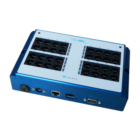
Page 13: Velmixlc Connections
Network connector: Enables Ethernet communication between VelmixLC and the POS. For future development. RJ45 serial connector: Serial communication between VelmixLC and a PC. This communication is only used during development as a debugging tool. During installation at a client's site, the technician doesn't need to bother with this connector, as it is unnecessary for the normal operation of VelmixLC. -
Page 14: Valve And Flowmeter Connections
Installation Guide Valve and Flowmeter Connections A single VelmixLC can control up to 16 beer lines. If the restaurant owner has more than 16 lines, then additional VelmixLCs are required. The number of VelmixLCs required by a restaurant owner may also vary according to the layout of the bars within the establishment. -
Page 15: Valve And Flowmeter Specifications
Cold rooms in restaurants are often located in the basement, with beer towers on the first floor. The VelmixLC provides sufficient power to the valves to allow them to open at a pressure of around 30 psi. This is the recommended operating pressure for this type of installation. However, the restaurant may have multiple floors with beer towers. - Page 16 Velmix LC Installation Guide ▪ Maximum cable length: 30 meters (90 feet) @50mA (4-conductor, 26AWG, telephone cable) ▪ Recommended flowmeter-side connection: 3M Scotchlok UY2 19-26AWG. Copyright © 2024 PayFacto Inc. Page 16 de 41...
-
Page 17: Wire Connections
Should you inadvertently reverse the connection between the flowmeter and the valve, this error is not likely to damage the VelmixLC circuit board, provided you have assembled your wires correctly. As the image below shows, the valve and flowmeter use different pins on the RJ45 connector. The valve terminals are connected to the connector's four central pins, while the flowmeter uses four peripheral pins. -
Page 18: Installation
Installation Guide Installation Installation This section explains how to install VelmixLC with your beer lines. NOTE: If you wish to use another beverage with VelmixLC, it is important to check with PayFacto before installing or changing the source(s) to ensure that the equipment is compatible with the beverage(s) you wish to control instead of (or in addition to) beer. -
Page 19: Installation Diagram
You will notice that: ▪ The VelmixLC is linked to the POS by a serial communication wire, null-modem, db9 female to db9 female. If your POS doesn't have a COM port for serial communication, you can use a USB-to-serial adapter, available from any computer equipment store. -
Page 20: Installation Considerations
▪ Be sure to screw VelmixLC to a solid base or wall. Avoid screwing VelmixLC into materials that may crumble, such as gypsum board. If the VelmixLC screw holes don't match the wall studs, screw a piece of plywood (or equivalent material) to the wall about 1.5 centimetres (5/8 inch) thick to provide a solid base for your installation. - Page 21 Velmix LC Installation Guide Copyright © 2024 PayFacto Inc. Page 21 de 41...
-
Page 22: Valve And Flowmeter Installation
Velmix LC Installation Guide Valve and Flowmeter Installation To integrate the flowmeters and valves into the beer lines in the cold room, you'll need to either cut the beer lines, or detach the hoses from a device that is part of the beer line. First, close the valve at the outlet of the beer barrel. - Page 23 Velmix LC Installation Guide There are two possible types of installation for VelmixLC, large cold room installations and smaller installations using a refrigerator under or near the bar. These different types do not necessarily use the same tubing size, so when you assess the client's requirements, be sure to consider the tubing size and choose the appropriate hose connections.
-
Page 24: Valve Connection
Using pliers, press firmly on the orange button to secure the contact between the different wires. For the network cable, it's important to insert both strands, as a single strand would overheat and possibly damage the cable when using VelmixLC. Copyright © 2024 PayFacto Inc. - Page 25 Velmix LC Installation Guide Repeat the procedure with the red wire of the copper cable and the other 2 “V+” strands of the network cable. The following image illustrates the final result. The final step is to connect the terminals to the valve. Copyright ©...
- Page 26 Velmix LC Installation Guide Copyright © 2024 PayFacto Inc. Page 26 de 41...
-
Page 27: Flowmeter Connection
Normally, the flowmeter should have three wires corresponding to Vcc, ground, and pulse output. When you consider the flowmeter most frequently used with VelmixLC installations, you will find this legend with the wire colors associated to the functions. If the cable leading out of the flowmeter is too long, trim the excess. - Page 28 Velmix LC Installation Guide Copyright © 2024 PayFacto Inc. Page 28 de 41...
-
Page 29: Connect Valves And Flowmeters To Velmixlc
Connect Valves and Flowmeters to VelmixLC To connect the valves and flowmeters to the VelmixLC, you'll need network cables running from the patch panel to the valves and flowmeters. Since the patch panel is located outside the cold room, and the valves and flowmeters are inside, you'll need to drill a hole in one of the walls to make the connections. - Page 30 Velmix LC Installation Guide Finally, install the brew panel back on its bracket and identify your valves and flowmeters. Copyright © 2024 PayFacto Inc. Page 30 de 41...
-
Page 31: Final Connections To Velmixlc
Installation Guide Final Connections to VelmixLC The final connection must now be made from the patch panel to the VelmixLC. Using patch cords, connect the valve and flowmeter cables from the patch panel to the VelmixLC. TIP: If possible, you should use different colored cables to easily identify the valve and flowmeter connections. -
Page 32: Connecting The Communications Cable To The Pos Workstation
Connecting the Communications Cable to the POS Workstation Take a null-modem serial communication cable with 2 female db9 connectors and plug one end into VelmixLC's serial communication port. Tighten the two thumb screws on either side of the connector to prevent accidental disconnection. - Page 33 Velmix LC Installation Guide Copyright © 2024 PayFacto Inc. Page 33 de 41...
-
Page 34: Start Up And Testing
Installation Guide Start Up and Testing Start Up and Testing This section explains how to start up the VelmixLC and ensure that it works correctly with your Point of Sale (POS) system. NOTE: The verification tests in this guide are performed using the Veloce POS. -
Page 35: Powering Up Velmixlc
Then plug the power supply unit into a back-up power supply or wall socket. When you connect the power supply to the VelmixLC, the LED at the top right of the VelmixLC lights up orange, indicating that the unit is ready for operation. - Page 36 Velmix LC Installation Guide Copyright © 2024 PayFacto Inc. Page 36 de 41...
-
Page 37: Verifying The Installation With Veloce
Steady orange: Indicates that the Velmix is operational and has not yet received an order from the POS after start- up. ▪ Alternating orange/red: Indicates that the bypass (latch position where valves are open) is active after VelmixLC start-up. ▪... -
Page 38: Checking Valve Operation
The second person must be located in the cold room, near the valves. Using the Veloce workstation, touch the buttons to open the valves one by one, informing the person standing in the cold room of both the beer type and the line number. The latter will listen to the valve's sound as it opens. - Page 39 Velmix LC Installation Guide Touch each beer button to open and close the valve: Copyright © 2024 PayFacto Inc. Page 39 de 41...
-
Page 40: Checking Flowmeter Operation
Go to the Veloce Quick Service screen and the draught beer menu. Order each beer in turn, then pour some of each order. On the Veloce bar service screen, the number of ounces remaining to be poured will appear below each order. - Page 41 Velmix LC Installation Guide Copyright © 2024 PayFacto Inc. Page 41 de 41...
Need help?
Do you have a question about the VelmixLC and is the answer not in the manual?
Questions and answers