Advertisement
Quick Links
Advertisement

Related Manuals for Novatech HBC-4301A

Summary of Contents for Novatech HBC-4301A
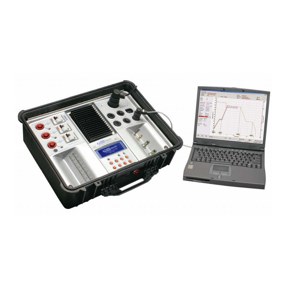
- Page 1 HBC-4301A Hot Bonding Controller Advanced Operators Manual & Calibration Supplied by March 2009...
- Page 3 8.2 Earth Socket ............................23 8.2 Other Safety Issues ..........................23 9. Quality Control Report ..........................25 Information Screen ............................25 Appendix A. HBC-4301A Calibration Check List ..................... 26 March 2009 Advanced Operators Manual HBC-4301A Hot Bonding Controller...
- Page 4 Neither the whole nor any part of the information contained in, or the product described in, this manual may be adapted or reproduced in any material form except with the prior written approval of Novatech Controls (Aust) Pty Ltd (Novatech Controls).
- Page 5 The procedure described in this document includes the calibration and a check of the functions of the HBC- 4301A control case. The calibration of the HBC-4301A control case is set from the control case by using the keypad and the display and the calibration factors are stored within the control case.
- Page 6 The calculation of the thermocouple temperature requires an accurate measurement of the temperature at the point where the thermocouple wire (or thermocouple compensating wire) is joined to copper wires. This is achieved in the HBC-4301A by using two solid-state temperature sensors mounted in thermal contact with the thermocouple input connectors.
- Page 7 1.3 The Display and Keypad The calibration of the HBC-4301A control case is all done from the local keypad and display. Above each key printed in blue writing is a description of the function of the key in Run Mode and below...
- Page 8 07 Vacuum 2 Calibration Calibrate Zero Calibrate Span 08 Phase / Burst Threshold Adjustable (0%/No phase to 100%/No burst) 09 Internal Clock Date and Time Adjustable 10 Serial Interface RS-485 2-wire RS-232 Advanced Operators Manual March 2009 HBC-4301A Hot Bonding Controller...
- Page 9 The DC power rails used by the electronics are derived from a switch mode power supply mounted in the base of the HBC-4301A. There are labelled test points for all the DC voltages accessible under the metal cover plate on the HBC4300-1 PCB.
- Page 10 9. Turn the power off and replace the metal shield on the PCB 10. The HBC-4301A will now need calibrating if the calibration data was reset in set #7 above. NOTE: The temperature accuracy of the HBC-4301A without calibration is generally +/- 3°C...
- Page 11 The software has been written to allow for either type K or type J thermocouples. NOTE: The compensation materials used in the thermocouple input connectors in the HBC-4301A are intended for K-type thermocouples. Mixing of compensation materials has the potential to create temperature offset, although in this application the affect is small given that the copper interface and Cold Junction occurs almost simultaneously.
- Page 12 Advanced Operators Manual March 2009 HBC-4301A Hot Bonding Controller...
- Page 13 The Ref #1, Ref#2 and Ref #3 test points are measured on the main PCB model HBC-4300-1. The PCB is mounted in the rear left hand corner of the base chassis under the shield in the HBC-4301A control case. March 2009...
- Page 14 The TC reference is measured on the thermocouple input PCB model HBC-4300-3 as shown below. The PCB is mounted on the underside of the main control console in the HBC-4301A control case. TC Reference Common TC Reference 12.25mV Figure 4: Thermocouple Input PCB Reference Voltage Test Point Measure and record the thermocouple reference voltage at the test points with the multimeter.
- Page 15 The reliability of the Cold Junction temperature measurement uses two independent sensors have been integrated into the HBC-4301A. Each sensor has separate circuitry to maintain operation in the event that one should fail. The Cold Junction temperature measurement is performed by averaging the reading from the two temperature sensors.
- Page 16 Advanced Operators Manual March 2009 HBC-4301A Hot Bonding Controller...
- Page 17 5. Use the cursor keys to select ‘Calibrate Span’, adjust the displayed value using the option keys until the displayed value matches the pressure of the regulated air supply and press enter. March 2009 Advanced Operators Manual HBC-4301A Hot Bonding Controller...
- Page 18 9. Exit the Calibration Menu and follow steps 5&6 above to turn off vacuum pump #2. 10. You may also wish to repeat step 4 above and return the vacuum pump control mode to its previous state. Advanced Operators Manual March 2009 HBC-4301A Hot Bonding Controller...
- Page 19 4. Next change the signal generator to output 20mA. 5. Use the cursor keys to select ‘Calibrate 20mA’ and press the enter key again. March 2009 Advanced Operators Manual HBC-4301A Hot Bonding Controller...
- Page 20 Advanced Operators Manual March 2009 HBC-4301A Hot Bonding Controller...
- Page 21 Lamp is barely turned on On with low intensity Burst Lamp flashes ~25% duty cycle 25% flash Burst Lamp flashes ~50% duty cycle 50% flash 100% Burst Mains voltage on lamp constantly March 2009 Advanced Operators Manual HBC-4301A Hot Bonding Controller...
- Page 22 7.2 Internal Vacuum Pumps There are two vacuum pumps in the HBC-4301A. Each can be configured independently to run and a fixed rate or via feedback from one of the vacuum sensors to a fixed vacuum level. Neither of the vacuum pumps can be calibrated but they must be checked for the ability to generate a vacuum at a specific leak rates.
- Page 23 During a 1 minute test check that the vacuum level is controlled at the rate of -65kPa. On completion try increasing and decreasing the leak rate from 0.1L/min up to 2L/min to confirm that the control case is capable of responding to changes in conditions. March 2009 Advanced Operators Manual HBC-4301A Hot Bonding Controller...
- Page 24 Advanced Operators Manual March 2009 HBC-4301A Hot Bonding Controller...
- Page 25 8.1 Earth Leak Detectors (Residual Current Detectors) The HBC-4301A has been designed to protect the operator from electric shock by using a separate Residual Current Detector (RCD) on each heater circuit. The RCD also doubles as the power on / off switch for the control case outputs.
- Page 26 Advanced Operators Manual March 2009 HBC-4301A Hot Bonding Controller...
- Page 27 Additional information on the calibration parameters can be obtained from the information screen. This screen is shown when the zone Power and the enter keys are pressed and held for 1 second. Use the function keys to scroll up and down through the information. March 2009 Advanced Operators Manual HBC-4301A Hot Bonding Controller...
- Page 28 PPENDIX HBC-4301A C ALIBRATION HECK Novatech Controls - HBC-4301A Checking Procedure Hot Bonding Controller Supplied to: Date EPROM ver. Serial No. PC software ver. Order No. Visual check Paint quality Cable ties Scratches on anodised parts Ferrites x2 Beeper link off...
- Page 29 Additional Checks Temperature cycle run Final check EPROM version EPROM date Serial number sticker Signed Calibration sticker Date March 2009 Advanced Operators Manual HBC-4301A Hot Bonding Controller...
Need help?
Do you have a question about the HBC-4301A and is the answer not in the manual?
Questions and answers