
Related Manuals for Sanyo PLV-Z8000


Summary of Contents for Sanyo PLV-Z8000
- Page 1 trusted dependable most name projector lamp sales. http://www.myprojectorlamps.com http://www.myprojectorlamps.ca http://www.myprojectorlamps.eu The following projector manual has not been modified or altered in any way.
- Page 2 Multimedia Projector PLV-Z4000 MODEL Owner’s Manual...
- Page 3 Features and Design This Multimedia Projector is designed with the most advanced technology for portability, durability, and ease of use. It uses built-in multimedia features, a palette of 1.07 billion colors, and matrix liquid crystal display (LCD) technology. Short Throw & Wide-Range Zoom Lens Automatic Slide Shutter ◆...
- Page 4 Table of Contents Features and Design . . . . . . . . . . . . . . . . 2 Input . . . . . . . . . . . . . . . . . . . . . . . . . . . . 24 Table of Contents .
- Page 5 To the Owner Before installing and operating the projector, read this manual Safety Precaution thoroughly. The projector provides many convenient features and ● THIS APPARATUS MUST BE EARTHED . functions. Operating the projector properly enables you to WARNING: manage those features and maintains it in good condition for ●...
- Page 6 Safety Instructions All the safety and operating instructions should be read before This projector should be operated only from the type of power the product is operated. source indicated on the marking label. If you are not sure of the type of power supplied, consult your authorized dealer or Read all of the instructions given here and retain them for local power company.
- Page 7 Safety Instructions Air Circulation Installing the Projector in Proper Position Openings in the cabinet are provided for ventilation. To Install the projector properly. Improper installation may reduce ensure reliable operation of the product and to protect it from the lamp life and cause fire hazard. overheating, these openings must not be blocked or covered.
- Page 8 Model Number(s) : PLV-Z4000 Trade Name : Sanyo Responsible party : SANYO NORTH AMERICA CORPORATION Address : 21605 Plummer Street, Chatsworth, California 91311 Telephone No. : (818)998-7322 AC Power Cord Requirement The AC Power Cord supplied with this projector meets the requirement for use in the country you purchased it.
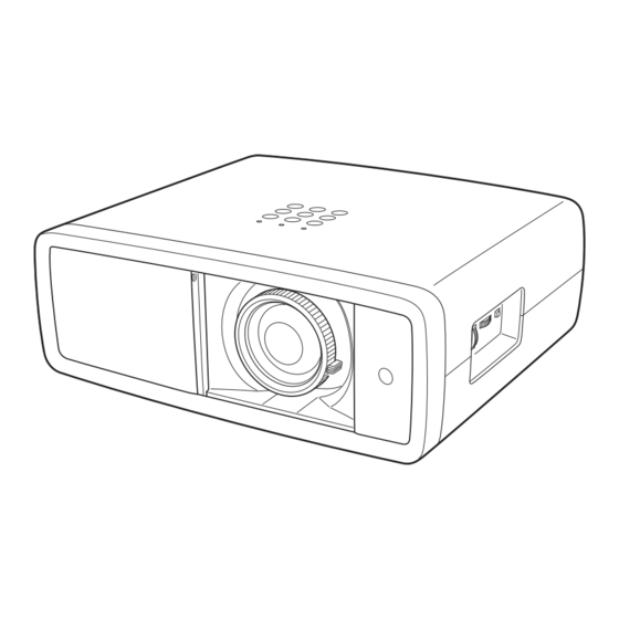
- Page 9 Part Names and Functions Front q Exhaust Vent Air flow CAUTION Hot air is exhausted from the exhaust vent. Do not put heat-sensitive objects near this side. w Top Controls and Indicators e Automatic Slide Shutter r Projection Lens t Focus Ring y Zoom Lever u Infrared Remote Receiver i Vertical Lens Shift Ring (Up/Down)
- Page 10 Part Names and Functions Rear Terminal q COMPUTER r SERVICE PORT Connect the computer output signal, or RGB Scart 21-pin This jack is used to service the projector. video output to this connector (p.16). t HDMI 1/HDMI 2* Connect the HDMI output signal from video equipment w S-VIDEO to these terminals (p.16).
- Page 11 Part Names and Functions Top Control t INPUT button q POWER indicator Lights red while the projector is in stand-by mode. Select an input source (p.24). – – Lights green during operations. – Blinks red during the cooling-off period. y POINT buttons ed7 8 –...
- Page 12 Part Names and Functions Remote Control q POWER ON/STAND-By button Turn the projector on or off (pp.18, 19). w RESET button Reset to the previous figure. This function is limited to when selecting the Image Adjustment (pp.28 – 33) and Picture Adjustment (p.34). e LIGHT button Light up the remote control buttons for about 10 seconds (p.22).
- Page 13 Part Names and Functions Remote Control Operating Range Point the remote control toward the projector (Infrared Remote Receiver) when pressing any buttons. Maximum operating range for the remote control is about 16.4’ (5 m) and 60 degrees in front of the projector. 16.4’...
- Page 14 Installation Positioning the Projector This projector is designed to project on a flat projection surface having a focus range of 3.9’ (1.2 m) to 30.2’ (9.2 m) at maximum zoom and 7 .9’ (2.4 m) to 60.4’ (18.4 m) at minimum zoom. Refer to the figure and table below for the screen size and distance between the projector and screen.
- Page 15 Installation Moving the Lens The projection lens can be moved up and down or left and right manually with the Lens Shift Rings, enabling you to adjust the position of a projected image. After adjusting the position, lock the lens with the Lens Shift Lock. Move the projection lens to the left or right with the Horizontal Horizontal Lens Shift Ring Lens Shift Lock...
- Page 16 Installation This projector can be connected up to six equipment at one time. See the figures below for the connections. Connecting to Video Equipment (Video, S-Video) Video, S-video Video Equipment Use a video cable or a S-video cable (commercially available). Composite S-VIDEO Video Output...
- Page 17 Installation Connecting to Video Equipment (HDMI, RGB Scart) HDMI RGB Scart Use a HDMI cable (optional) for HDMI output. Use a Scart-VGA cable (optional). Video Equipment Video Equipment HDMI Video RGB Scart Output 21-pin Output HDMI Scart-VGA Cable Cable COMPUTER HDMI Connecting to a Computer Computer (Analog)
- Page 18 Installation Connecting the AC Power Cord This projector uses nominal input voltages of 100 – 120 V or 200 – 240 V AC and it automatically selects a correct input voltage. It is designed to work with the single-phase power systems having a grounded neutral conductor.
- Page 19 Basic Operation Turning On the Projector Complete peripheral connections (with a computer, VCR, Main On/Off switch etc.) before turning on the projector. Connect the projector’s AC power cord into an AC outlet and turn the Main On/Off switch on. The POWER indicator lights red.
- Page 20 Basic Operation Turning Off the Projector Press the POWER ON/STAND-BY button on the top control or on the remote control. “Power off?” appears on the screen. Press the POWER ON/STAND-BY button again to turn off the projector. When the Power off confirmation function is set to “Off, ” the projector can be turned off without the confirmation message.
- Page 21 Basic Operation How to Operate the On-Screen Menu The projector can be adjusted or set via the On-Screen Menu. Top Control The menus have a hierarchical structure, with a main menu that is divided into submenus, which are further divided into other submenus.
- Page 22 Basic Operation Menu and its Functions For the detailed menu contents, see the Menu Tree on pages 54 – 55. Main Menu Sub-Menu q Image Select an image mode from among Brilliant cinema, Creative cinema, Pure cinema, Natural, Living, Dynamic, x.v.Color, and User image 1 – 7 (p.27). w Image adj .
- Page 23 Basic Operation Zoom and Focus Adjustment Rotate the Zoom Lever to zoom in and out. Rotate the Focus Ring to focus the image. Zoom Lever Focus Ring Remote Control Operation For some frequently used operations, using the remote control is advisable. Just pressing one of the buttons enables you to have the desired operation quickly, and no need for calling up the On-Screen Menu.
- Page 24 Basic Operation IMAGE MODE buttons Remote Control Press the IMAGE MODE buttons (PRESET or USER) to select the IMAGE MODE desired image mode of the screen. For details, see page 27 . buttons IMAGE ADj . button BRIGHTNESS IMAGE ADj . button Press the IMAGE ADJ.
- Page 25 Input Input Source and System Selection Press the INPUT button on the top control or the INPUT buttons on Top Control INPUT button the remote control (see below) to choose an input source. Video S-video ✔ Note: Component 1 • Before selecting an input source with these buttons, each input must be set on a proper signal form via menu operation (see on pages 25 –...
- Page 26 Input Input Menu Menu Operation Use the Point buttons to select the Input Menu and press the Point or OK buttons to access the submenu items. Use the Point buttons to select an input source and press the Point or OK buttons. The selected item is check marked.
- Page 27 Input HDMI 1 or HDMI 2 When the video signal is connected to the HDMI 1 or HDMI 2 terminals, select HDMI 1 or HDMI 2 respectively. The projector automatically detects the incoming video signal and adjusts itself to optimize its performance. If the output signal of video equipment and the input signal of the projector do not match, you might not get an image with the best quality.
- Page 28 Image Image Mode Selection Image mode selection can be made for each input source. Remote Control Direct Operation Press the IMAGE MODE buttons (PRESET or USER) on the remote control to select the desired image mode. Press the PRESET button to select Brilliant cinema, Creative IMAGE MODE cinema, Pure cinema, Natural, Living, Dynamic, or x.v.Color;...
- Page 29 Image Adjustment Image Mode Adjustment Image mode can be adjusted for each input source and the adjustment is kept until the projector is turned off or the image mode is changed. Direct Operation Remote Control Press the IMAGE ADJ. button on the remote control to display the adjustment bar of Image adj.
- Page 30 Image Adjustment White balance (Red) Press the Point button to lighten red tone; press the Point button to deepen red tone (from -31 to +31). The selected item. White balance (Green) Press the Point button to lighten green tone; press the Point button to deepen green tone (from -31 to +31).
- Page 31 Image Adjustment Advanced menu This function can be selected only when Advanced menu in the Setting Menu (see page 37) is set to “On. ” You can adjust the following items through this function. Iris mode Adjust the lamp aperture. Select from the following options: Mode 1.
- Page 32 Image Adjustment Dynamic gamma Set the level for Dynamic gamma correction. Select from the following options: Off ..Disable dynamic gamma correction Low ..Small correction Mid ..Medium correction High .
- Page 33 Image Adjustment Color data box COLOR MANAGEMENT COLOR MANAGEMENT LIST COLOR MANAGEMENT LIST Select Color management in the Advanced menu and then press the Point or OK buttons. The COLOR MANAGEMENT LIST appears. You can store up to eight (8) color management data in the list.
- Page 34 Image Adjustment Reset To reset the adjusted data, select Reset and press the Point OK buttons. A confirmation box appears. Select [Yes] and then press the OK button. All adjustments return to their previous figures. You can also reset the adjusted data by pressing the RESET button on the remote control.
- Page 35 Picture Adjustment Picture Position and Screen Adjustment Some input source employ special signal formats which may not be tuned by the auto-tuning system of this projector. Picture Adjustment enables you to precisely adjust several parameters manually to match those signal formats. The parameters manually adjusted is stored for every input.
- Page 36 Screen Screen Size Adjustment This projector has the picture screen resize function which enables you to customize the image size. Remote Control Direct Operation Press the SCREEN button on the remote control to select a screen size from among Full, Zoom, Normal, Natural wide, and SCREEN button Anamorphic.
- Page 37 Screen Vertical adj . When it is in the Zoom or Anamorphic mode, press the Point buttons to display the Vertical adj. dialog box. Use the Point buttons to adjust the vertical position. The adjusting range differs depending on the input signal. The adjusted value is only effective in the Zoom and Anamorphic mode.
- Page 38 Setting Setting The Setting Menu allows you to set up other various functions described below. Setting Menu Press the Point buttons to select the Setting Menu and press the Point or OK buttons to access the submenu items. Use the Point buttons to select the desired item and press the Point or OK buttons to access the selected item.
- Page 39 Setting HDMI 1 setup/ HDMI 2 setup HDMI 1 setup Select Normal or Enhanced according to the output signal of video equipment. Press the Point or OK buttons to switch between each option. Normal ..When the output of video equipment is set to “STANDARD.
- Page 40 Setting Rename Rename This function is used to change the name of the Input or the User image. Select Rename and press the Point or OK buttons. The Rename window appears. Use the Point buttons to choose either Input or User image and then press the Point or OK buttons to display the rename item selection window.
- Page 41 Setting Display This function decides whether to display the On-Screen displays. Press the Point or OK buttons to switch between each option. On ... Show all the On-Screen displays. Use this function when you want to project images after the lamp becomes bright enough.
- Page 42 Setting Power management Power management For reducing power consumption as well as maintaining the lamp life, the Power management function turns off the projection lamp when the projector is not used for a certain period. When this function is “On” and if the input signal is interrupted and no button is pressed for more than 30 seconds, the timer display with “No signal”...
- Page 43 Setting Test pattern Filter counter A test pattern for zoom and focus adjustment is available for use when setting up the projector. Filter counter This function is used to set a frequency for the filter cleaning. When the projector reached a specified time between cleanings, a Filter warning icon appears on the screen, notifying the cleaning is necessary.
- Page 44 Information Input Source Information Display The Information Menu is used for checking the status of the image signal being projected and the operation of the projector. Direct Operation Top Control Press the INFO. button on the top control or on the remote control to display the Information Menu.
- Page 45 Maintenance and Cleaning Warning Indicator The WARNING indicator shows the state of the function that protects the projector. Check the state of the WARNING indicator and the POWER indicator to take proper maintenance. The projector is shut down and the WARNING indicator is blinking red. TOP CONTROL When the temperature inside the projector reaches a certain level, the projector is automatically shut down to protect its inside.
- Page 46 Maintenance and Cleaning Cleaning the RGB panels Blemishes such as dust and dirt on the internal optical components of the projector tend to degrade the brightness of the screen and are likely to appear as a shadow on the screen, which can lead to deterioration of image quality. This projector has the RGB panel cleaning holes on the underside for cleaning of the internal parts (such as optical components) of the projector.
- Page 47 Maintenance and Cleaning Cleaning Clean by using the Cleaning function in the Setting Menu Turn the projector on and press the MENU button to display the On-Screen Menu. Select the Setting Menu with the Point buttons. Press the Point or OK buttons to access the submenu items.
- Page 48 Maintenance and Cleaning Cleaning the Air Filter The air filter prevents dust from accumulating on the surface of the optical elements inside the projector. Should the air filter becomes clogged with dust particles, it will reduce cooling fan’s effectiveness and may result in a buildup of internal heat and adversely affect the life of the projector.
- Page 49 Maintenance and Cleaning Resetting the Filter Counter Be sure to reset the Filter counter after cleaning or replacing the air filter. Filter counter Turn the projector on and press the MENU button to display the On-Screen Menu. Select the Setting Menu with the Point buttons.
- Page 50 Maintenance and Cleaning Lamp Replacement When the projection lamp of this projector reaches its end of life, the LAMP REPLACE indicator emits yellow light. If this indicator Top Control lights yellow, replace the lamp with a new one promptly. The time when the LAMP REPLACE indicator should light is depending on the lamp mode.
- Page 51 Maintenance and Cleaning Resetting the Lamp Replacement Counter Be sure to reset the lamp replacement counter after the lamp is replaced. When the lamp replacement counter is reset, the LAMP REPLACE indicator stops lighting. Lamp counter reset Turn the projector on and press the MENU button to display the On-Screen Menu.
- Page 52 Appendix Troubleshooting Before calling your dealer or service center for assistance, check the items below once again. – Make sure you have properly connected the projector to peripheral equipment as described in “Connecting to Video Equipment” and “Connecting to a Computer” on pages 15 – 16. –...
- Page 53 Appendix Problem: – Solutions Horizontal line noise occurs. – When connecting HDTV equipment to the projector’s COMPONENT 1/2 terminals, horizontal line noise may be noted only occasionally. Then adjust the value of Fine sync. (see page 34). Image is Left/Right reversed. –...
- Page 54 Appendix Indicators and Projector Condition Check the indicators for projector’s condition. Indicators Projector Condition POWER LAMP WARNING REPLACE red/green/ orange yellow The Main On/Off switch is off or the AC power cord is unplugged. The projection lamp is being cooled down. The projector cannot be turned ✽...
- Page 55 Appendix Menu Tree Input Video / S-Video Auto Component 1 SECAM NTSC Component 2 NTSC 4.43 PAL-M HDMI 1 PAL-N Quit HDMI 2 Computer RGB (Analog) RGB (Scart) Quit Image Image adj . Brilliant cinema Brightness -31 to +31 Creative cinema Contrast -31 to +31 Pure cinema...
- Page 56 Appendix Picture adj . Setting Overscan 0 to +10 Language English Horizontal -100 to +100 German ❖ Vertical -100 to +100 French ✽ Auto adj. Italian Fine sync 0 to +31 Spanish Total dots -100 to +100 Portuguese Dutch When 480i/575i input, -8 to +8. - - - ❖...
- Page 57 Appendix System Mode Chart PLV-Z4000 can basically accept the signal from all computers and some video equipment with V- and H-Frequency mentioned below and less than 100 MHz of Dot Clock. H-Freq . V-Freq . H-Freq . V-Freq . System System (kHz) (Hz)
- Page 58 Appendix Technical Specifications Projector Type Multimedia Projector Dimensions 15.75” x 5.75” x 13.62” (400 mm x 146 mm x 346 mm) (not including raised portions) (W x H x D) Net Weight 16.5 lbs (7 .5 kg ) LCD Panel System 0.74”...
- Page 59 Appendix Configurations of Terminals Video terminal Terminal: HDMI Pin Configuration TMDS Data 2+ Input Ground (TMDS Clock) Ground (TMDS Data 2) TMDS Clock- Input 1 3 5 7 9 11 13 15 17 19 TMDS Data 2- Input ----- TMDS Data 1+ Input ----- Ground (TMDS Data 1) 19 Pin Type A...
- Page 60 Appendix Dimensions Unit: inch (mm) 15.75 (400) 2.09 (53) 6.5º 3.45 (87.7) 6.31 (160.3)
- Page 61 ME4AE SANyO Electric Co ., Ltd .
Need help?
Do you have a question about the PLV-Z8000 and is the answer not in the manual?
Questions and answers