Table of Contents
Advertisement
Quick Links
Advertisement
Table of Contents

Summary of Contents for NTC FIVEGENTECH ACU132
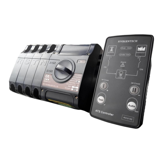
- Page 1 ACU132 ATS CONTROLLER USER MANUAL NTC TECHNOLOGY CO.,LTD.
- Page 2 Version history Date Version Content 2015-10-10 Original release Clarification of notation used within this publication. Sign Instruction Highlights an essential element of a procedure to ensure correctness. NOTE Indicates a procedure or practice, which, if not strictly observed, could result in CAUTION! damage or destruction of equipment.
-
Page 3: Table Of Contents
ACU132 ATS Controller User Manual CONTENTS 1. OVERVIEW ..........................5 2. PERFORMANCE AND CHARACTERISTICS ................5 3. SPECIFICATION ........................6 4. PANEL DESCRIPTION ......................7 4.1. FRONT PANEL ........................ 7 4.2. KEY FUNCTION DESCRIPTION ..................7 4.3. INDICATOR DESCRIPTION .................... 8 4.4. - Page 4 ACU132 ATS Controller User Manual 11.3. INSTALLATION ......................25 12. TROBLESHOOTING ......................25 ACU132 ATS Controller 2015-10-10 Version 1.0 Page 4 of 25...
-
Page 5: Overview
ACU132 ATS Controller User Manual 1. OVERVIEW ACU132 ATS Controller is suitable for No Neutral Position 2-Stage ATS. It can accurately detect 2-way-3-phase voltage and judge voltage abnormal (such as over voltage, under voltage, over frequency, under frequency, lack of phase and phase reverse), then control ATS to transfer. When ATS switch abnormally, the controller can detect close failure and alarm on the front panel to ensure the correct action of ATS. -
Page 6: Specification
ACU132 ATS Controller User Manual 3. SPECIFICATION Items Contents AC power A1N1/A2N2 supply. Operating Voltage Rated AC240V (range: AC170V~277V) Power Consumption Under rated voltage, power consumption is not more than 3VA AC Voltage Input: AC170V – AC277V (ph-N) 3-phase 4-wire AC170V –... -
Page 7: Panel Description
ACU132 ATS Controller User Manual 4. PANEL DESCRIPTION 4.1. FRONT PANEL 4.2. KEY FUNCTION DESCRIPTION Icon Function Description Auto/Manual mode switch; Auto (Setting) Enter into lamp test status by pressing for 3s; Enter into parameter configuration mode by pressing for 8s. 1# Close in Manual mode;... -
Page 8: Indicator Description
ACU132 ATS Controller User Manual 4.3. INDICATOR DESCRIPTION Indicators Description Lamp on: 1# power voltage exceeds over volt threshold; 1# Over Volt Lamp off: 1# power voltage is under over volt return value; Lamp on: 2# power voltage exceeds over volt threshold; 2# Over Volt Lamp off: 2# power voltage is under over volt return value;... -
Page 9: Close Failure Alarm
ACU132 ATS Controller User Manual CLOSE FAILURE ALARM Close Failure Alarm is devided into 1#Close Failure and 2#Close Failure. After close failure alarms, the alarm indicator will flash with 1Hz. Trigger process of 1#Close Failure Alarm: 1#Volt is normal and 1#Close order is sent; if 1#Close input signal can’t be detected, open and re-trip;... -
Page 10: High/Low Voltage And High/Low Frequency Adjustment
ACU132 ATS Controller User Manual 6.3. HIGH/LOW VOLTAGE AND HIGH/LOW FREQUENCY ADJUSTMENT ACU132 ATS Controller 2015-10-10 Version 1.0 Page 10 of 25... -
Page 11: Connection
ACU132 ATS Controller User Manual 7. CONNECTION 7.1. TERMINALS Terminal Item Function Note Single phase: connect to A2, N2; B2 and C2 hang in the air; 2# AC 3-phase 4-Wire 2-phase 3-wire: connect to A2, B2, N2; C2 hang in the air; Input 3-phase 3-wire: connect to A2, B2, C2 after hardware adjusted;... -
Page 12: Programming And Communication
ACU132 ATS Controller User Manual 7.2. PROGRAMMING AND COMMUNICATION Install “M58 Driver Windows.exe” (the driver is suitable for Windows 2000, Windows XP and Windows7 only) before M58 adaptor connecting to PC. After drivers have been installed, open “Control Panel”-“Device Manager” to check Ports (COM & LPT). - Page 13 ACU132 ATS Controller User Manual Open ACU13X software, it can communicate normally after selected correct COM port. ACU132 ATS Controller 2015-10-10 Version 1.0 Page 13 of 25...
-
Page 14: Definition And Range Of Parameters
ACU132 ATS Controller User Manual 8. DEFINITION AND RANGE OF PARAMETERS Form1 Items Range Default Description Power Supply System (1-4) 1: 3-phase 4-wire 2: Single-phase 2-wire 3: 3-phase 3-wire (need to modify circuit board) 4: 2-phase 3-wire 1# Volt Normal Delay (1-7) 1: 1s 2: 5s... - Page 15 ACU132 ATS Controller User Manual Items Range Default Description 3: 5s 4: 8s 5: 10s 6: 15s 7: User defined(Default: 3s) Transfer Delay Expired (1-7) 1: 0.5s 2: 1s 3: 2s 4: 3s 5: 4s 6: 5s 7: User defined(Default: 0.5s) Start Delay (1-7) 1: 3s...
- Page 16 ACU132 ATS Controller User Manual Form2 Item Range Default Description Rated Volt (170-270)V Provide base for over/under volt judge. Rated Freq (50.0-60.0)Hz 50.0 Provide base for over/under frequency judge. Over Volt Monitor 0: Disabled (0-1) Enabled 1: Enabled Over Volt Threshold (100-120)% Threshold Over Volt Return...
-
Page 17: Parameters Setting
ACU132 ATS Controller User Manual 9. PARAMETERS SETTING 9.1. PARAMETERS SETTING MODE In manual mode, enter into parameters setting mode by pressing for 8s and Manual/Auto indicator flashes; ① , ② , ③ , ④ , ⑧ , ⑨ indicators illuminate. and Gen Status indicator Note: Press this time, it can be back to normal mode after LED flashed. -
Page 18: Reset To Default
ACU132 ATS Controller User Manual Indicators Indicators Value Value ① ② ③ ④ ⑤ ⑥ ⑦ 9.3. RESET TO DEFAULT , ⑧ , ⑨ indicators flashes and ① , ② , ③ , ④ indicator are off; press , ⑧ , In parameter setting mode, press ⑨... -
Page 19: Typical Application
ACU132 ATS Controller User Manual 10. TYPICAL APPLICATION 10.1. TYPE A (4P ATS. 3P4W 380V. 40A-125A) Operate Current 3.5A 10.2. TYPE B (4P ATS. 3P4W 380V. 160A-400A) Operate Current 16A ACU132 ATS Controller 2015-10-10 Version 1.0 Page 19 of 25... -
Page 20: Type C
ACU132 ATS Controller User Manual 10.3. TYPE C (4P ATS. 3P4W 380V. 630A-1600A) Operate Current 16A 10.4. TYPE M (4P ATS. 3P4W 380V. 630A-1250A) Operate Current 16A ACU132 ATS Controller 2015-10-10 Version 1.0 Page 20 of 25... -
Page 21: Type Hs
ACU132 ATS Controller User Manual 10.5. TYPE HS (2P 100A ATS. 1P2W 220V) Operate Current 1.6A 10.6. TYPE HS (2P 200A ATS. 1P2W 220V) Operate Current 4.85A ACU132 ATS Controller 2015-10-10 Version 1.0 Page 21 of 25... -
Page 22: Type Top3
ACU132 ATS Controller User Manual 10.7. TYPE TOP3 (2P 125A ATS. 1P2W 220V) Operate Current 3.5A 10.8. TYPE TOP3 (3P 125A ATS. 3P3W 220V) Operate Current 3.5A ACU132 ATS Controller 2015-10-10 Version 1.0 Page 22 of 25... -
Page 23: Type Top3
ACU132 ATS Controller User Manual 10.9. TYPE TOP3 (4P 125A ATS. 3P4W 380V) Operate Current 3.5A 10.10. TYPE W (4P ATS. 3P 4W 380V) Operate Current 2.7A~6.4A ACU132 ATS Controller 2015-10-10 Version 1.0 Page 23 of 25... -
Page 24: Verall Dimension And Panel Cutout
ACU132 ATS Controller User Manual 11. VERALL DIMENSION AND PANEL CUTOUT 11.1. CASE DIMENSION Unit: mm 11.2. CUTOUT The controller has three installation ways: panel built-in, internal 35mm slideway and internal screw mounting. Panel built-in and internal screw mounting are as below: ACU132 ATS Controller 2015-10-10 Version 1.0... -
Page 25: Installation
ACU132 ATS Controller User Manual 11.3. INSTALLATION A)Fixing Clips B) 35mm Slideway C) Screw Mounting 12. TROBLESHOOTING Symptom Possible Remedy Check power connections and voltage of 1# and 2#; Controller inoperative Check F1 or F2 fuse Check ATS; Switch not activate Check the connections between controller and ATS.
Need help?
Do you have a question about the FIVEGENTECH ACU132 and is the answer not in the manual?
Questions and answers