Advertisement
Quick Links
TECHNICAL
INFORMATION
AND
SERVICE
DATA
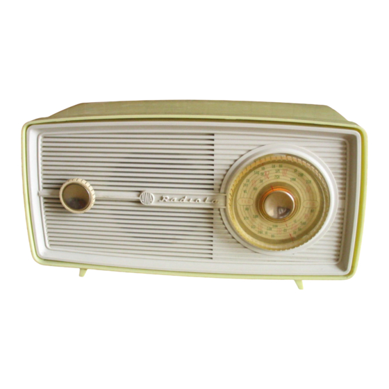
<§>RADIOLA
MODEL 495-MA
FOUR VALVE, BROADCAST, A.C. OPERATED
SUPERHETERODYNE
Issued by:
AMALGAMATED WIRELESS (AUSTRALASIA) LTD.
ELECTRICAL
Frequency Range
. .
540-1600 Kc/s
(555-187.5 Meters)
Intermediate Frequency . .
455 Kc/s.
Power Supply Rating . .200-260 volts A.C.
50 C.P.S.
Power Consumption . .
35 watts
Undistorted Power Output .
1.5 watts
Loudspeaker: 4" Permanent Magnet
Transformer No. 21472A
V.C.
Impedance —
15 OHMS
at
400 C.P.S.
Connection to Power Supply:
The
receiver
should
not
be
connected
to
any
circuit
supplying other than 200-260 volts A.C. at a frequency of
50 C.P.S.
The
connections
on
the
power
transformer
are
shown
below.
RED DOT INDICATES COMMON
CONNECTION FOR ALL VOLTAGES
□
□
S'
230-260
200-230
VOLTS
VOLTS
SPECIFICATIONS
Valve Complement
6BE6 Converter
6AU6 I.F. Amplifier
6BV7
Detector, A.V.C.
High
Gain
Output
6X4 Rectifier
CHASSIS REMOVAL:
The chassis together with the fret is removed by removing
the two screws at the back of the cabinet. This allows complete
accessibility to the top and bottom of the chassis and to the
pilot lamp.
Should it ever be necessary to remove the front fret, first
remove the tuning and volume control knobs. These are only
push on fits;
however in the case of the tuning
control,
forcing the knob past its free travel with a twisting action
is necessary to overcome friction between the knob and the
gang spindle.
Remove the dial scale.
The fret is held to the chassis by three screws, one under
the volume
Control spindle
and
two
in vertical
line
with
the gang spindle.
NOTE: On
removing the dial scale, two other screws are
accessible through the fret. These
hold the gang onto
its
mounting
bracket and
may
be
loosened
off for centering
the gang spindle with relation to the fret.
Reassembly is the reverse of the above. After replacing
the tuning control the pointer should be
lined up on the
State Monograms on either side of the dial scale. Check the
calibration
on
some
known
stations
and
correct
for
any
tracking error by forcing the knob past its free travel
In
the appropriate direction.
Advertisement


Need help?
Do you have a question about the RADIOLA 495-MA and is the answer not in the manual?
Questions and answers