Advertisement
Quick Links
Advertisement

Subscribe to Our Youtube Channel
Summary of Contents for JTX Fitness STRIDER X7
- Page 1 J T X C Y C L O - 3 J T X S T R I D E R X 7 USER MANUAL USER MANUAL...
- Page 2 USER MANUAL TABLE OF CONTENTS SECTION 1. ASSEMBLY SAFETY PRECAUTIONS ..... ..YOUR EQUIPMENT ....... ASSEMBLY INSTRUCTIONS .
- Page 3 Thank you for purchasing the JTX: Slim-Line treadmill. We set up JTX Fitness in 2009 with a very simple aim; to help you reach your fitness goals, effectively, safely and with the best customer service in the industry. Here’s how we will support you to transform your health and fitness, for life.
- Page 4 Section 1 Assembly & Maintenance Thank you for purchasing a JTX Strider X7. Section 1 will show you how to set up and maintain your Cross Trainer. Our customer service team are always on hand if you need extra help. JTX CUSTOMER SERVICE: Email: info@jtxfitness.com...
- Page 5 SAFETY PRECAUTIONS The JTX Strider X7 is designed and built for optimum safety. However, certain safety precautions apply. Please note the following: IF YOU HAVE ANY KNOWN MEDICAL CONDITION, OR PHYSICAL LIMITATION, THAT MAY INTENSIFY THE EFFECTS OF EXERCISE, WE RECOMMEND YOU CONSULT A DOCTOR BEFORE STARTING A NEW EXERCISE ROUTINE.
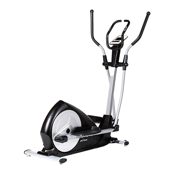
- Page 6 YOUR EQUIPMENT Handlebars Computer Main Frame Foot plates Adjustable Feet PAGE 5...
- Page 7 Please consult the machine diagram and parts lists on pages 26 - 28 to identify the individual parts of your new Cross Trainer. This will help you with assembly. ASSEMBLY PA CK 1 x Multi-tool 2 x Allen Key 1 x Spanner 2 x Hex screw M8 X 100 (61) 2 X Spring washer (26) 2 x Flat washer (63)
- Page 8 ASSEMBLY INS T RUCTI ONS The Strider X7 is easy to assemble but if you need further guidance, we have additional videos available on our website.. Step One: FRONT & REAR SUPPORTS Remove the protective packaging from the stabiliser area, retaining the bolts. This packaging can be disposed of.
- Page 9 Step Two: HANDLEBAR POST Attach the Protective guard (58) around the Handlebar post (4). Connect the Extension wire from the Handlebar Post (59) with the Tension Control (57) together. Fit the Handlebar post (4) onto the Main frame (1) with the 4 Hex Screws (53), 4 Spring washers (18) and 4 Flat washers (12), and then slide the Protective guard (58) down to cover in place.
- Page 10 Step Three: SWING ARMS and PEDAL SUPPORT Insert the Long axle (56) through the Handlebar post (4) then attach the Swing tube (7L/R) on the Long axle (56) with wave washer (21), D-shape washer (24), flat washer (60), spring washer (25) and Hex screw (26). Do not fully tighten yet. Fix the Pedal support(8L/R) on the Crank (20) with Hex screw (26), Spring washer (25), Flat washer (60), D-shape washer (24) and Wave washer (21).
- Page 11 Step Four: HANDLEBARS Attach the 2 swinging handlebars (6L/R) onto the 2 swing tubes (7L/R) and fix tightly with the 4 carriage bolts (44), 4 Arc washers (43) and 4 nylon nuts (13). Take the fixed handlebar and thread the pulse wires (55) into the hole on the handlebar post (4) and pull them through and out of the top of the post.
- Page 12 Step Five: PROTECTIVE GUARDS PLEASE TAKE PARTICULAR CARE TO AVOID DAMAGE TO THE INTERNAL CABLE WHEN FITTING THE PLASTIC CASING. PLEASE LOOK THROUGH THE HOLES ON CENTRAL COLUMN AND ENSURE CABLE IS NOT IN VIEW. IF CABLE IS IN VIEW, PLEASE USE A FINGER TO MOVE TO THE SIDE BEFORE FITTING THE CASING.
- Page 13 Step Six: COMPUTER CONSOLE First connect the extension wire (59), hand pulse wires (55) with the matching wires from the back of the computer console (47). Make sure all wires are pushed back down the post or into the back of the computer and then attach the computer (47) on the bracket of the handlebar post (4) with the 4 screws (35) (These screws are already attached to the back of the computer).
- Page 14 Step 7: CENTRAL PROTECTIVE GUARD The sequence of this last step is very important. Make sure to start with part 51A. This is the part which is positioned on the central column on the OPPOSITE side to where you would stand to use the machine.
- Page 15 SE T -UP & HA NDL I NG I NS TRUCTIO NS These steps should be taken before you begin your training session, for optimum safety and performance. 1. The machine should be set up on a hard, level surface in an area free of obstructions and as the descriptions in the instruction manual.
- Page 16 Section 2 Using Your JTX Strider X7 Section two is aimed at helping you get the most from your new cross trainer. We'll guide you through how to use the computer. PAGE 15 PAGE 4...
- Page 17 COMPUTER OPERATION The console will: 1) Record the user’s data of GENDER, HEIGHT, WEIGHT and AGE. 2) Dot matrix showing your current status 3) Simulative ECG measuring the heart rate 4) Display Speed, Time, Distance, Calories, Watt, Pulse and Level at same time. 5) The computer will turn off automatically if there is no operation, speed signal and pulse signal over 4 minutes.
- Page 18 COMPUTER OPERATION OPERATION 1. Turn on the computer Plug in one end of the adaptor to the AC electrical source and connect the other end to the computer. The computer will beep and enter into initial mode. 2. Program select and value setting Manual Program and Preset Program P1 P10 A.
- Page 19 COMPUTER OPERATION 4. Heart Rate Control: 55% H.R, 75% H.R and 90% H.R The maximum heart rate depends on your age A. Press UP , DOWN button to choose the heart rate control program. B. Press ENTER to confirm the heart rate control program, and enter into time setting window.
- Page 20 COMPUTER OPERATION 6. Custom 1 – Custom 4 A. Press UP, DOWN button to select the user. B. Press ENTER to confirm your choice, and enter into time setting window. C. The time display will flash, and then press UP, DOWN button to set up the desired time to do the exercise.
- Page 21 COMPUTER OPERATION 7. Body Fat Measurement A. Press UP, DOWN button to select BODY FAT TEST program. B. Press ENTER to confirm your choice, and enter into height setting mode. C. The height display will flash, and then press UP, DOWN button to set up your height. Press ENTER to confirm the value.
- Page 22 COMPUTER OPERATION 8. Pulse Recovery Test The pulse recovery test is to compare your heart rate before and after exercise. It is target to determine your heart strength via the measuring. Please do the test as below: A. Both your hands hold the pulse sensor or via wireless transmitter belt to test the pulse (if applicable), the computer will display your current pulse value.
- Page 23 COMPUTER PROGRAMMES The JTX Fitness Cyclo Go has 21 programmes as following: 1 x MANUAL 10 x PRESET P1 - ROLLING P2 - VALLEY P3 - FATBURN P4 - RAMP P5 - MOUNTAIN P6 - INTERVAL P7 - CARDIO P8 - ENDURANCE...
- Page 24 COMPUTER PROGRAMMES 1 x WATT CONTROL 4 x HEART RATE CONTROL TARGET HR 4 x CUSTOM 1 x BODY FAT MEASURING PAGE 23...
- Page 25 Section 3 Trouble Shooting Warranty Parts List PAGE 24 PAGE 4...
- Page 26 TROUBLE SHOOTING Your equipment is designed to be reliable and durable. However, if you do experience problems with your machine, please reference the troubleshooting guide listed below. PROBLEM: The console does not light up SOLUTION: Please check the following: The outlet the machine is plugged into is functional. Double check that the breaker has not tripped.
- Page 27 CERTIFICATE OF WARRANTY This is to certify that your JTX Strider X7 is under warranty with JTX Fitness. There is no need to register your warranty. All warranties are registered automatically on purchase. 2 YEAR IN-HOME WARRANTY The JTX Strider X7 comes with a 2-year in-home repair warranty.
- Page 28 EXPLODED DRAWING PAGE 27...
- Page 29 EXPLODED DRAWING PAGE 28...
- Page 30 PARTS LIST PAGE 29...
- Page 31 JTX CUSTOMER SERVICE: Email: info@jtxfitness.com Phone: 01273 453855...
Need help?
Do you have a question about the STRIDER X7 and is the answer not in the manual?
Questions and answers