Advertisement
Quick Links
Advertisement

Related Manuals for Firmtech FBS100BC

Summary of Contents for Firmtech FBS100BC
- Page 1 FBS100BC Quick Guide (Switch / LED Test Board)
- Page 2 Category Control the Switch and the LED using FBS100BC Practice to use 4 bits of the PIO [PIO7-PIO4] as output and other 4 bits of the PIO [PIO3-PIO0] as switch input Push Switch PIO3~PIO0 Input PIO7~PIO4 Output Chip LED...
- Page 3 (Name of the file to be downloaded : of the switch and LED connected to the FBS100BC. FBS100BC_start.apk)
- Page 4 Chapter 1. Switch, LED Test Board Overview...
- Page 5 1. Switch, LED Board (Components) It is configured such that this practice can be done with FBS100BC. The hardware is configured such that 4 bits of the PIO [PIO7-PIO4] can be used as output and other 4 bits of the PIO [PIO3-PIO0] as switch input...
- Page 6 2. Switch, LED Board - Photos showing the FBS100BC before and after mounting Photos showing the FBS100BC Photos showing the FBS100BC before mounting after mounting...
- Page 7 The Master Board is configured such that it can be freely mounted or removed for various function tests with no soldering process. All signal lines of FBS100BC are delivered to the switch, LED board using the signal connection cable. Master...
- Page 8 It is configured such that the FBS100BC can be freely mounted or removed with ① FBS100BC mounting socket no soldering process. It is configured such that all signal lines of FBS100BC can be checked using a measuring ② Test Point instrument such as an oscilloscope.
- Page 9 5. Pin assignment of the Master Board Pin No Description STATUS FA SET UART_RTS UART_CTS PIO7 PIO6 PIO5 PIO4 Pin No.1 Pin No.20 PIO3 PIO2 PIO1 PIO0 ADC0 ADC1 Frontside Backside...
- Page 10 This is the on/off switch for power supplied to ⑦ Switch the main board. ⑤ Reset Switch It is the reset switch for FBS100BC. ⑧ Signal Connection Delivers all signals lines of the FBS100BC to the ② ⑨ Cable switch/LED board. ③ ① ④...
- Page 11 7. Switch, LED Test Board - PIO pin settings for FBS100BC ① PIO 7 ~ PIO 4 Output Chip LED ② PIO 3 ~ PIO 0 Input Push Switch ① ② Switch, LED Test Board...
- Page 12 8. Switch, LED Test Board - Detail hardware configuration Switch PIO0 PIO3~PIO1 have the same hardware structure with PIO0 Switch Input Switches are configured on the LED Test Board. LED Output PIO4 ◆ PIO3-PIO0 4 bits are used as input for the switch. PIO7~PIO5 have the same hardware ◆...
- Page 13 9. Switch, LED Test Board - Schematic...
- Page 14 Chapter 2 Switch, LED Test Board Control Practice...
- Page 15 1. What is the Switch, LED Control Practice ? This practice is to learn how to use the upper 4 bits out of the 8 bits of the PIOs of the FBS100BC as output and the lower 4 bits as input.
- Page 16 Run the Firmtech App on the smartphone after making the Bluetooth connection between the smartphone and FBS100BC and then control all 4 LEDs connected to each of the 4 bits of the PIOs set as output on the FBS100BC and make their outputs change High ->...
- Page 17 This is a practice to read the input values of the eight push button switches connected to each of the 8 bits of the PIOs set as the input of the FBS100BC after the Bluetooth connection between the smartphone and the FBS100BC and running the Firmtech App on the smartphone, then send the values to the smartphone and display them on the smartphone’s screen.
- Page 18 4. Explanation of the Switch, LED control Practice Proceed in the order of ① → ② → ③ as shown in the picture below. (Remarks: Please refer to the next page for the Step 2 and The Master starts inquiry and the Slave starts scanning relatively.
- Page 19 4 bits of the The values of the switches Master Slave PIO set as the input of FBS100BC after the pressed are read and sent. Bluetooth connection between the smartphone and FBS100BC and running the Firmtech App...
- Page 20 5. Explanation of the Switch, LED control Practice ① Detail explanation (1) Outline At the Step ①, the Master starts inquiry and the Slave starts scanning. Proceed with the Bluetooth connection between the Master and Slave devices after the pairing process. Slave Master...
- Page 21 ① Detail explanation (2) The FBS100BC starts the Bluetooth scanning as the Slave. ◆ Connect the FBS100BC Interface Board and the PC using the USB cable (to supply 5V power). ◆ Turn the main power switch from OFF to ON.
- Page 22 (3) Check the arrangements before using the smartphone (Android) for practice. ◆ Click the Firmtech Icon on the smartphone. ◆ Please download the Firmtech app from our company’s homepage and install it yourself. (Name of the file to be downloaded: FBS100BC_start.apk)
- Page 23 5. Explanation of the Switch, LED control Practice ① Detail explanation (4) Start screen when running the Firmtech App. Click the GPIO Test Board. Click the Smartphone Menu button in the activated window.
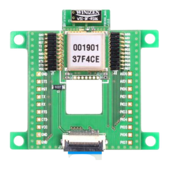
- Page 24 ◆ Start the Bluetooth connection by clicking the FBS100 found in the Inquiry process. (Remarks: The MAC address found on the practice screen is 00:19:01:37:F4:CE. All the MAC addresses are unique and each MAC address for each FBS100BC is different. )
- Page 25 5. Explanation of the Switch, LED control Practice ① Detail explanation (6) To enter the pin code Pin code entry is required when the Bluetooth connection between the smartphone and FBS100BC is made normally. Enter “0000” or “1234” as the pin code.
- Page 26 5. Explanation of the Switch, LED control Practice ① Detail explanation (7) The Bluetooth connection between the smartphone and FBS100BC is completed. The screen that appears when the Bluetooth connection between the smartphone and FBS100BC is normally made.
- Page 27 (1) Outline In Step ②, when an output command is sent to the FBS100BC through the button operation on the LEDs after the Bluetooth connection is made between them, the FBS100BC operates the embedded PIO as ON (0V-Low) or OFF (3.3V-High) according to the output command.
- Page 28 (2) Initial status after running the app Digital Output PIO7-PIO4 are shown as . This means all ports on the FBS100BC operate as High (3.3V). (In this case, all LEDs are turned off. See the circuit diagram below.) ◆ The toggle switch by which...
- Page 29 6. Explanation of the Switch, LED control Practice ② Detail explanation (3) Turning on all LEDs The Digital Output PIO7-PIO4 buttons are changed from when touched by hand in order as shown in the picture below. This means that all output from Digital Output PIO7-PIO4 operate as Low (0V). (In this case, all LED are on.) ◆...
- Page 30 6. Explanation of the Switch, LED control Practice ② Detail explanation (4) Turning off all LEDs The Digital Output PIO7-PIO4 buttons are changed from when touched by hand in order as shown in the picture below. This means that all output from Digital Output PIO7-PIO4 operate as High (3.3V). (In this case, all LEDs are turned off.) ◆...
- Page 31 Read the input values of the eight push button switches connected to each of the 4 bits of the PIO set as the input of FBS100BC after the Bluetooth connection between the smartphone and FBS100BC and running the Firmtech App on the smartphone, then send the values to the smartphone and display them as on the smartphone’s screen.
- Page 32 All digital inputs of PIO3-PIO0 are shown as , which means that High (3.3V) is supplied to all PIO3-PIO0 ports embedded on the FBS100BC. (In other words, switches are not pressed. See the circuit diagram below for your reference.) If the switch is OFF (not pressed), a High (3.3V) value is sent to the PIO0.
- Page 33 Detail explanation (3) Explanation of the screen content of the smartphone according to the pressing of the push switches When you press the PIO0 switch on the FBS100BC by hand, the PIO0 on the smartphone screen is changed from It shows meaning Low (OV) only during when the button is pressed and returns to meaning High (3.3V).
Need help?
Do you have a question about the FBS100BC and is the answer not in the manual?
Questions and answers