Advertisement
Quick Links
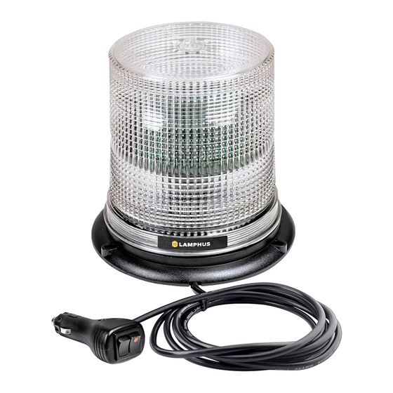
AURA™ Series LED Beacon
Manual ID: PIM-00000101-V002
IMPORTANT: READ CAREFULLY BEFORE ASSEMBLY AND USE.
•
Installer of this product must have a good understanding of automotive electronics,
systems, and procedures.
•
In the case that holes must be drilled in order to properly mount the product, the installer
must examine both sides of the mounting surface before drilling begins. It is the
installer's responsibility to be sure that no vehicle components or vital parts could be
damaged by the drilling process. De-burr any holes in order to remove metal shards and
remnants. Use grommets in all wire passage holes.
•
If this manual states that this product may be mounted with suction cups, magnets,
tape, or Velcro®, clean the mounting surface and dry thoroughly prior to applying any
adhesives for maximum adhesion.
•
Do not attempt to activate or operate this product under hazardous driving situations.
Flash Patterns:
Sim. = Simultaneous – all LEDs flash at the same time.
Rotator – LEDs flashes sequentially in a rotating fashion.
A = Type A – Type A flashes simultaneously with Type A, alternates with Type B
B = Type B – Type B flashes simultaneously with Type B, alternates with Type A
1.
Single Burst 75 Sim. A
2.
Single Burst 75 Sim. B
3.
Single Burst 150 Sim. A
4.
Single Burst 150 Sim. B
5.
Double Burst 75 Sim. A
6.
Double Burst 75 Sim. B
7.
Double Burst 150 Sim. A
8.
Double Burst 150 Sim. B
9.
Quad Burst 75 Sim. A
1 0 .
Quad Burst 75 Sim. B
11.
Quad Burst 150 Sim. A
12.
Quad Burst 150 Sim. B
13.
Steady Mode
14.
Single Flash 75 Sim. A
15.
Single Flash 75 Sim. B
16.
Single Flash 120 Sim. A
17.
Single Flash 120 Sim. B
18.
Single Flash 150 Sim. A
19.
Single Flash 150 Sim. B
20.
Single Flash 300 Sim. A
21.
Single Flash 300 Sim. B
22.
Double Flash 75 Sim. A
23.
Double Flash 75 Sim. B
24.
Double Flash 120 Sim. A
25.
Double Flash 120 Sim. B
26.
Quad Flash 75 Sim. A
27.
Quad Flash 75 Sim. B
28.
Quad Flash 150 Sim. A
29.
Quad Flash 150 Sim. B
30.
2 Double 75 Sim. / 4 Quad 120 Sim.
31.
4 single 75 Sim. / 4 Quint 120 sim.
32.
Cycle Mode.
33.
Accelerator Sim.
34.
Single Flash 90 Rotator
35.
Single Flash 120 Rotator
36.
Single Flash 150 Rotator
37.
Single Flash 300 Rotator
38.
Off
True Mods © 2012-2021 All Rights Reserved
•
Deployment area of the vehicle air bags must be cleared. Do not install this product
or route any electrical wires near the air bags deployment areas. Refer to your
vehicle owner's manual for the air bag deployment area. Products or wires mounted
in the air bag deployment area will damage, reduce the effectiveness of the air bag,
or even act as a projectile which may cause serious injury or death. The user/installer
of this product assumes full responsibility in determining the proper mounting
location while prioritizing the safety of all passengers in the vehicle.
•
This product contains strobe light(s), halogen light(s), high-intensity LEDs, or a
combination of these components. Do not look directly into the lights. Momentary
blindness and/or injury to the eyes could result.
Functions with Cigarette Lighter Plug:
1.
Power unit on/off via rocker switch with LED indicator light.
2.
Select flash patterns via momentary rocker switch.
3.
Refer to the function of the BLUE wire in the following section for
more functions that can be achieved utilizing the momentary rocker
switch.
Wiring without Cigarette Lighter Adapter:
WARNING! All customer supplied wires that connect to the positive
terminal of the battery must be sized to supply at least 125% of the
maximum operating current and FUSED at the battery to carry that load.
DO NOT USE CIRCUIT BREAKERS WITH THIS PRODUCT!
- BLACK: To Chassis Ground
- RED: To 12-24V DC Power Source
- BLUE: Pattern Selection
-
Apply BLUE to BLACK for a brief second will advance LED beacon to
the Next flash pattern.
-
Apply BLUE to BLACK for 1-3 seconds will advance LED beacon to
the Previous flash pattern.
-
Apply BLUE to BLACK for 3-5 seconds will advance the LED beacon
to Steady mode.
-
Apply BLUE to BLACK for 5-10 seconds will advance the LED beacon
to Off mode. Unit will resume the last known flash pattern when
powered off from Off and powered back on again.
-
Apply BLUE to Black for more than 10 seconds will advance the LED
beacon to flash pattern # 1.
- YELLOW: Synchronization
-
Connect YELLOW of all LED beacon units together to enable
synchronization.
Specifications:
Input Voltage: 12 – 24 V DC
Input Current: 1.2A MAX @ 12 V DC
Output Power: 12 WATTS
www.truemods.com
US Toll Free: 1-855-533-6654
International: 1-909-212-0993
Fax: (909) 575-6722
E-mail: support@truemods.com
Advertisement

Summary of Contents for Lamphus AURA Series
- Page 1 www.truemods.com US Toll Free: 1-855-533-6654 International: 1-909-212-0993 Fax: (909) 575-6722 E-mail: support@truemods.com AURA™ Series LED Beacon Manual ID: PIM-00000101-V002 IMPORTANT: READ CAREFULLY BEFORE ASSEMBLY AND USE. • Installer of this product must have a good understanding of automotive electronics, • Deployment area of the vehicle air bags must be cleared.
- Page 2 Permanent Mount Diagram: Mounting: IMPORTANT! It is not recommended to put the vehicle in motion when the LED beacon is mounted to the exterior of the vehicle magnetically. The use of any magnetically - Apply magnet protection sticker - Apply magnet protection sticker mounted warning beacon on the outside of a vehicle that is in motion is at the sole discretion and responsibility of the user.
Need help?
Do you have a question about the AURA Series and is the answer not in the manual?
Questions and answers