Advertisement
ELECTRONIC CONTROL UNIT
LRS 2102 NEW SET
- Mod.
Single-phase electronic control unit for the automation of
sliding gates with incorporated radio receiver.
I
MPORTANT FOR THE USER
- The device can be used by children over 8 years of age
and persons with reduced physical or psychological
abilities or with little knowledge and experience only if
supervised or educated in its operation and safe use, in
order to also understand the dangers involved in its use.
- Do not allow children to play with the device and keep
the radio controls away from their reach.
- Frequently examine the system to detect any signs of
damage. Do not use the device if it is in need of repair
work.
-Always remember to disconnect the power supply
before carrying out any cleaning or maintenance.
- Cleaning and maintenance must not be carried out by
unsupervised children
- ATTENTION: keep this instruction manual safe and
observe the important safety requirements contained
herein. Failure to comply with the requirements may
cause damage and serious accidents.
IMPORTANT FOR THE INSTALLER
1) Before automating the gate, check that it is in good
conditions, in compliance with the Machinery Directive
and with EN 12604.
2) Check that the location where the installation is
located enables compliance with operating temperature
limits specified for the device.
3) The safety of the final installation and compliance
with all prescribed Standards (EN 12453 - EN 12445) is
the responsibility of the person who assembles the
various parts to construct a total closing.
4) It's recommended to use safety devices with a
connection self test.
5) Once installation is finished, it is recommended that
all necessary
checks
programming of the control panel and correct installation
of safety devices) to ensure that compliant installation
has been performed.
6) Fix the control unit to the wall using the appropriate
support. This support should be facing downwards:
insert the screws in the spaces provided.
7) The control unit does not have any type of isolating
device for the 230 Vac line. It is therefore the
responsibility of the installer to set up an isolating device
inside the system. It is necessary to install an omnipolar
switch, surge category III. It must be positioned to
provide protection from accidental closing, pursuant to
point 5.2.9 of EN 12453.
: 433.92 MHz "narrow band"
be performed (appropriate
8) Cables for power and connection to the motor
suitable for insertion in the pg9 cable glands provided
must have an outside diameter between 4.5 and 7 mm.
The internal conductor wires must have a nominal
section of 0.75mm2. If a raceway is not used, use
H05RR-F cables. Pay careful attention when fastening
the cables so that they are anchored in a stable manner.
GB
Furthermore, care is required when drilling holes in the
outside casing where connecting and power supply
cables will pass, and when assembling the cable glands,
so that everything is installed so as to maintain the
panel's IP protection characteristics.
9) The gearmotor used to move the frame must comply
with that prescribed at point 5.2.7 of EN 1245
10) In compliance with 5.4.2 of EN 12453, it is
recommended to use gearmotors equipped with an
electric-mechanical release device, so that the door can
be moved manually in case of necessity.
11) In compliance with 5.4.3. of EN 12453, use electric-
mechanical release systems or similar devices which
stop the door safely in the end run position.
12) The various electrical components external to the
control unit must be cabled in accordance with standard
EN 60204-1 as amended, and as set forth in point 5.2.7
of EN 12453. Power cables may have a maximum
diameter of 14 mm.
must be fixed using the cable glands provided.
13) The assembly of a push button panel for manual
control must be completed positioning the push button
panel in such a way that the user is not placed in a
dangerous position.
14) The safety function ensured by the control unit is
active only during closing, therefore, protection on
opening must be ensured in the installation phase with
measures (guards or safety distances) independent of
the control circuit.
15) For proper functioning of the radio receiver, if using
one or more control units, the installation at a minimum
distance of at least 3 metres one from the other is
recommended.
complies with the requirements of Directives
RED 2014/53/EU, EMC 2014/30/EU, LVD
Power supply and connection cables
The electronic control unit:
LRS 2102 NEW SET
2014/35/EU.
Advertisement
Table of Contents

Summary of Contents for Gruppo Norton LRS 2102 NEW SET
- Page 1 Furthermore, care is required when drilling holes in the outside casing where connecting and power supply : 433.92 MHz “narrow band” LRS 2102 NEW SET - Mod. cables will pass, and when assembling the cable glands, Single-phase electronic control unit for the automation of so that everything is installed so as to maintain the sliding gates with incorporated radio receiver.
-
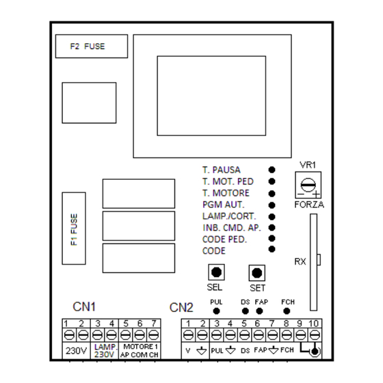
Page 2: Technical Data
TECHNICAL DATA: OPERATING FEATURES: - Power supply : 230 Vac 50/60Hz 900W(4A) max. Step-by-step operation: - Flashing beacon output : 230 Vac 50/60Hz By using either the radio-control ( CODE led on ) or the low 100W Resistive Load max. voltage buttons to activate the gate, you obtain the following 50W Inductive Load max. - Page 3 using the SEL key to move to the LAMP/CORT flashing LED PROGRAMMING: then press the SET key, and the LAMP/CORT flashing LED will switch on steady. The SEL key: this selects the type of function to be Repeat the operation if you wish to restore the factory setting. memorised, which is indicated by a flashing Led.
-
Page 4: Extended Menu
the SET key again, and in that moment the automatic complete. The control unit will now operate in Anti-Collision (pedestrian) mode. closing time will be memorised and the T. PAUSA LED If you wish to enable the Anti-Collision (pedestrian) function for will stay on steady. -
Page 5: Led Management
---------------------- EXTENDED MENU 2 ----------------- Level Leds On CODE CODE – CODE PED. CODE – CODE PED – IN.CMD.AP. CODE – CODE PED – IN.CMD.AP. – LAMP/CORT CODE – CODE PED – IN.CMD.AP. – LAMP/CORT – PGM.AUT 6 CODE – CODE PED– IN.CMD.AP. – LAMP/CORT – PGM.AUT – T.MOT Deceleration Programming The control unit allows you to programme the power used to carry out the deceleration phase.
Need help?
Do you have a question about the LRS 2102 NEW SET and is the answer not in the manual?
Questions and answers