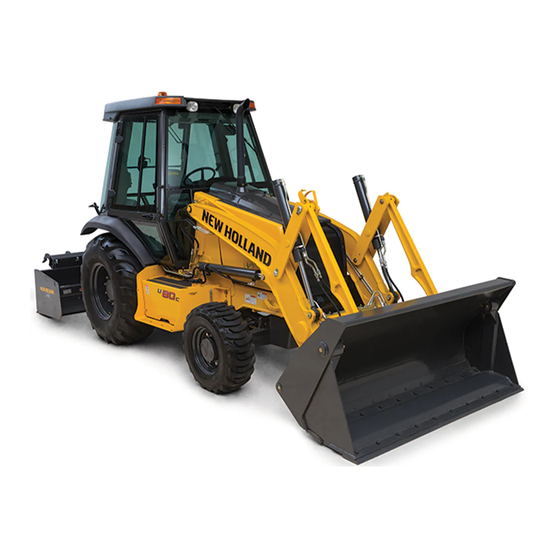
Summary of Contents for New Holland U80C Tier 4
- Page 1 SERVICE MANUAL U80C Tier 4 Tractor Backhoe from PIN NCC570800 Part number 47441616 edition English September 2012...
- Page 2 Contents INTRODUCTION Engine..................10 Engine and crankcase ..............10.001 Fuel tanks .
- Page 3 Three-point hitch cylinder..............35.116 Remote control valves .
- Page 4 Cab/Platform harnesses and connectors..........55.510 Cab engine controls .
- Page 5 INTRODUCTION 47441616 27/09/2012...
-
Page 6: Table Of Contents
Contents INTRODUCTION Safety rules ..................3 Safety rules Ductile iron . -
Page 7: Safety Rules
INTRODUCTION Safety rules DANGER Improper operation or service of this machine can result in an accident. Do not operate this machine or perform any lubrication, maintenance, or repair on it until you have read and understood the operation, lubrication, maintenance, and repair information. Failure to comply will result in death or serious injury. -
Page 8: Safety Rules Ductile Iron
INTRODUCTION Safety rules Ductile iron DANGER Improper operation or service of this machine can result in an accident. Any unauthorized modifications made to this machine can have serious consequences. Consult an authorized dealer on changes, additions, or modifications that may be required for this machine. Do not make any unauthorized modifications. -
Page 9: Safety Rules
INTRODUCTION Safety rules Before welding on the machine you must do the following. If you have any questions about welding on the machine contact your dealer. Disconnect the batteries. • Disconnect the alternator terminal wires. • Disconnect the instrument cluster. •... -
Page 10: Safety Rules
INTRODUCTION Safety rules Unless otherwise instructed, always perform these steps before you service the machine: Park the machine on a flat, level surface. Place the loader bucket on the ground, with the bottom of the loader bucket parallel to the surface. Place the direction control lever and the transmission in neutral. -
Page 11: Basic Instructions Important Notice Regarding Equipment Servicing
Some information could not be updated due to modifications of a technical or commercial type, or changes to the laws and regulations of different countries. In case of questions, refer to your NEW HOLLAND CONSTRUCTION Sales and Service Networks. 47441616 27/09/2012... -
Page 12: Basic Instructions Battery
INTRODUCTION Basic instructions Battery WARNING Explosive gas! Batteries emit explosive hydrogen gas and other fumes while charging. Ventilate the charging area. Keep the battery away from sparks, open flames, and other ignition sources. Never charge a frozen battery. Failure to comply could result in death or serious injury. W0005A WARNING Hazardous chemicals! - Page 13 INTRODUCTION Disconnect the negative battery cable from the neg- ative battery terminal. RCPH11TLB003AAM Master disconnect switch (if equipped) Enable or disable electrical power from the machine bat- teries to the electrical components using the master dis- connect switch, located on the right hand side of the en- gine.
-
Page 14: Basic Instructions Fuse And Relay Locations
INTRODUCTION Basic instructions Fuse and relay locations The machine is equipped with three fuse box locations. In the front console, a side console box and an external location. Front console - Engine Control Unit (ECU) fuse and relay Open the manual storage compartment located in front of the steering wheel. - Page 15 INTRODUCTION Side console box Find the fuse cover panel on the right hand side below the loader control handle. Loosen both retaining screws and remove the panel cover. RAPH12UTL0106AA RAPH12UTL0122AA Remove the fuse box covers as needed. RAPH12UTL0117AA RAPH12UTL0118BA 47441616 27/09/2012...
- Page 16 INTRODUCTION Refer to the decal on the interior side of the panel cover for fuse, relay, and/or diode functions. RAPH12UTL0121AA Glow-plug Control Unit (GCU) fuse Raise the loader arm and engage the safety support. Lift the engine hood. Locate the 60 A fuse box for the GCU on the right hand side of the engine.
-
Page 17: Basic Instructions Fuse, Relay And Diode Icon Definitions
INTRODUCTION Basic instructions Fuse, relay and diode icon definitions Right hand side console panel Power Shuttle 84386682A Fuse icon definitions Symbol Function Engine Control Unit (ECU) B+ Instrument cluster key ON Instrument cluster B+ Rear lights Rear wipers/washers 47441616 27/09/2012... - Page 18 INTRODUCTION Function Symbol Transmission differential lock Tail lights Cigarette lighter plugs 4WD, Glide ride Dome light Radio B+ Horn Blower motor Key switch 2WD, Glide ride Quick coupler, EH Clam, Radio Key ON SAHR brake Comfort Steer Customer B+ 47441616 27/09/2012...
- Page 19 INTRODUCTION Function Symbol Head lights Front work lights Turn signal, Hazards Front wiper/washer High beam Beacon Transmission de-clutch Customer key ON Relay icon definitions Symbol Function Transmission De-clutch relay Transmission lock relay Start relay Spring Applied Hydraulic Release (SAHR) park brake relay SAHR park brake transmission cutout relay Forward relay...
- Page 20 Thanks very much for your reading, Want to get more information, Please click here, Then get the complete manual NOTE: If there is no response to click on the link above, please download the PDF document first, and then click on it. Have any questions please write to me: admin@servicemanualperfect.com...


Need help?
Do you have a question about the U80C Tier 4 and is the answer not in the manual?
Questions and answers