Download Print this page
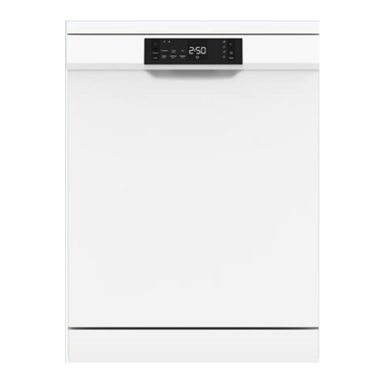
Electrolux A15 Service Manual

Electrolux A15 Service Manual

Structural characteristics, components & accessibility
Hide thumbs Also See for A15:

Advertisement

Quick Links

SERVICE MANUAL
Structural characteristics,
Components &
Accessibility
FOR INTERNAL AND PARTNERS USE ONLY
© ELECTROLUX BA APAC&MEA
TECHNICAL DOCUMENTATION
ELECTROLUX THAILAND
1910 ELECTROLUX BUILDING
NEW PETCHBURI RD BANGKAPI, HUAI KHWANG
BANGKOK, 10310
DISHWASHER
FREESTANDING
SEMI INTEGRATED
Voltage: 110V & 220V
User interface: A1E,A21,A22,A23
User interface: A15
EN
Publication number
599858462
Edition: 03/2022 - Rev. 00

Advertisement

loading
Need help?

Need help?

Do you have a question about the A15 and is the answer not in the manual?

Questions and answers

Subscribe to Our Youtube Channel

Summary of Contents for Electrolux A15

  • Page 1 ๆ Voltage: 110V & 220V SERVICE MANUAL User interface: A1E,A21,A22,A23 Structural characteristics, Components & Accessibility User interface: A15 FOR INTERNAL AND PARTNERS USE ONLY Publication number 599858462 Edition: 03/2022 - Rev. 00 © ELECTROLUX BA APAC&MEA TECHNICAL DOCUMENTATION ELECTROLUX THAILAND...
  • Page 2 CONTENTS 1. TOOLS FOR DISASSEMBLE ..................... 5 2. USER INTERFACES ......................... 7 2.1 A1 SERIES W/O DISPLAY (A15) ....................7 2.2 A1 SERIES W DISPLAY-W/O DIVERTER (A1E) ................. 7 2.3 A2 SERIES W/ DIVERTER (A21, A22, A23) ................8 3. WASHING PROGRAM ......................9 3.1 WASHING PROGRAM SEQUENCES CROSS TABLE ...............
  • Page 3 12.3 DC FAN ........................... 69 12.4 Asyncronous with Double Windings and/or Autodoor ............... 69 13. ELECTRICAL COMPONENTS ....................70 13.1 AQUAZONE ..........................70 13.2 DOOR LOCK ........................... 70 13.3 CIRCULATION PUMP ......................70 13.4 FLOATER ..........................71 13.5 CAPACITOR ..........................71 13.6 DRAIN PUMP ..........................
  • Page 4 15.25 KNOB REMOVAL INSTRUCTIONS ..................101 15.26 DISPENSER REMOVAL INSTRUCTION ................101 15.27 DOOR LOCK REMOVAL INSTRUCTIONS ................. 103 15.28 ELECTRONIC CARD REMOVAL INSTRUCTIONS ............. 104 15.29 CONTROL PANEL ......................105 15.30 KICK PLATE SHEET IRON ....................106 15.31 FRONT PANEL ........................107 14.32 SIDE PANELS REMOVAL INSTRUCTIONS ...............
  • Page 5 1. TOOLS FOR DISASSEMBLE 1.Phillips screwdriver For use • All kinds of star-head screw • In the phllips screws of the in ternal components. 2.Plier For use • It is used to bend all kinds of sheet metal end 3.Multimeter For use •...
  • Page 6 5.Side cutter For use • It is used to cut cables of internal components or any hard part. 6.Chageable drill For use • It is the most important tool used to remove and install all kinds of screws in the machine TECNICAL SUPPORT 599858462 REV.00...
  • Page 7 2. USER INTERFACES 2.1 A1 SERIES W/O DISPLAY (A15) The user interface includes: • On/Off button with integrated led • Up/down button • Program leds • Half Load button with integrated led(Half Load led) • Tablet button with integrated led (Tablet led) •...
  • Page 8 • Half Load buttons • Tablet button Note: At the beginning date of 09.10.2020, for all A1 digit and A2 models; • In A1 digit and A2 models, When the program is stopped, in addition to the S/P led, the washing progress (wash-rinse-dry) led should also blink. •...
  • Page 9 • Start/Stop and Reset button with integrated led • Half Load button with integrated led(Half Load led) • Tablet button with integrated led (Tablet led) 3. WASHING PROGRAM 3.1 WASHING PROGRAM SEQUENCES CROSS TABLE A15- A1E MODEL PREWASH JETWASH 14’ QUICK 30’...
  • Page 10 Hygiene 70°C Intensive 65°C Super 50' 65°C 50°C Smart 50°C - Intensive 65°C 60°C Smart 60°C - 70°C 3.3 SHARP PROGRAM NAME AND ICONS Program. A15 & A1E Prewash Prewash Prewash Prewash Quick 30' 40°C Quick 30' 40°C Quick 30' 40°C Quick 30' 40°C...
  • Page 11 Express 50' 65°C Everyday 60°C 50°C 50°C Intensive 65°C Express 50' 65°C Express 50' 65°C Everyday 60°C / Auto Intensive 65°C Express 50' 65°C Auto 30°C-50°C Hygiene 70°C Auto Intensive 65°C Auto 50°C-60°C Auto Auto 60°C-70°C 3.4 PROGRAM ICON TECNICAL SUPPORT 599858462 REV.00...
  • Page 12 3.5 WASHING SPECIFICATIONS AND PROGRAMS 3.5.1 SELECTING AND STARTING PROGRAM AT POWER ON (BEFORE PROGRAM STARTS) - When the machine is energized, all led + digits should stay lit (A1,A2,A3,A4) until the program information (ready position or any other status, remaining step) is displayed on the display.
  • Page 13 3.5.3 OPENING AND CLOSING DOOR DURING PROGRAM (NOT IN DRY STEPS) During the program if the door is opened and re-closed without any modifications on the program button the program continues. Washing program re-starts after 8” if the measured temperature is equal or more than 45°C. (1) For model w/o Display COMMANDS On/Off Start/Stop...
  • Page 14 *When the door is opened, Dry led is ON together with the blinking Start/Stop led. *When the door is closed, Dry led is ON. (2) For model w/ Display COMMANDS On/Off Start/Stop Wash Rinse Blink Door open Door closed 3.5.6 OPENING AND CLOSING DOOR DURING PROGRAM (IN REGENERATION SECOND STEP) During regeneration and resin washing step: if the door is opened and re-closed, the program continues.
  • Page 15 Pressure of Start/Stop Blink* button Door closed If user selects a program when the door is open, related program duration is seen on the display. Then, if user presses Start/Stop button, duration of the selected program led blinks. After closing the door, Wash led is ON and selected program starts. 3.5.8 TERMINATION OF A PROGRAM (END OF PROGRAM) (1) For model w/o Display COMMANDS...
  • Page 16 For A1 with digit, A2, A3, A4 models. • Display shows “0:01” during cancelation process. Dry led is on. When cancellation is paused, Dry led blinks. Display is off at the end of the cancelation process and only end led ,on/off led, salt/rinse aid lack leds (if salt/rinse aid tanks are empty) are on. (For A1 with digit and A2 models, this is valid from 01.12.2020).
  • Page 17 If the washing duration is lower than the washing duration of new program, go on with washing step. When new program is selected, display duration is changed to same step of new program. (1) For model w/o Display COMMANDS On/Off Start/Stop Wash Washing cycle is in progress...
  • Page 18 (2) For model w/ Display COMMANDS On/Off Start/Stop Wash Rinse Digit Duration Washing cycle is in ON/OFF ON/OFF ON/OFF progress program Duration Pressure of Start/Stop Blinks button 3” program Drain of water Blinks 0:01 End of Drain duration Select new program of new program * Display shows “0:01”...
  • Page 19 (2) For model w/ Display On/Off Start/Stop Wash Rinse Digit COMMANDS Duration ON/OFF ON/OFF ON/OF Washing cycle is in progress program Machine is “POWER OFF” ON/OFF ON/OFF ON/OF Machine is Duration “POWER ON ON/OFF ON/OFF ON/OF Select new Duration of new program* program Blink...
  • Page 20 3.5.16 MODIFICATION OF A PROGRAM DURING DELAY TIME • While delay timer is selected but not started or started and paused, if any program button is pressed, delay timer is cancelled and machine goes to ready state. NOTE: When it is started as delayed, the delay icon becomes active. (1) For model w/o Display Selected Related program...
  • Page 21 (2) For model w/ Display COMMANDS On/OFF Start/Stop Delay Icon Digit During delay time Delay duration Mains voltage is cut (Power off) Mains voltage is Delay duration blinks back(Power on) twice and then resumes Select new Delay duration program 1” Delay duration, 1” Pressure of Start/Stop duration of new program...
  • Page 22 • After the first two step of a salt regeneration cycle: at the power on the washing program will end and the resin wash will be performed at the beginning of the next washing cycle. After a Power Fail washing program re-starts without any delay if temp. is less than 45 ̊ C. After a Power Fail washing program wait 8”...
  • Page 23 The incompatible options must be off. (valid from 15.01.2021) (1) For model w/o Diverter Option A12-A1B A13-A1C A14-A1D A15-A1E Delay Half load Tablet (1) For model w/ display-w/ diverter. Option Delay Half load(3 modes)
  • Page 24 Tablet option Extra Hygiene option Extra Rinse option Extra Drying option Silent Wash Extra Silent option Extra Fast option Energy Save option Upper Basket Direct Wash Lower Basket Triple Wash Turbidity Sensor (Smart Wash) WARNINGS & PHASES Control Mobile Panel Display Application ICON DEFINITION...
  • Page 25 5.2 COMPATIBILITY BETWEEN OPTIONS Extra Extra Options Delay Half Table Child Extra Extra Extra Energy Fast Silent Timer Load( 3 Lock Rinse save Hygiene modes ) Delay Timer Half Load ( 3 modes ) Tablet Child Lock Extra Rinse Extra Hygiene Extra Dry Energy save...
  • Page 26 Half Extra Extra Extra Child load(3 A23 Series Delay Tablet Hygiene Rinse Lock modes) Prewash Quick 30’ Eco 50°C Daily 60°C Super 50’ Auto Delicate Auto Normal Auto Intensive 5.4 OPTION DEFINITION Option Short description Delay Timer Program starts with a delay The wash is executed with upper spray Half Load(3 modes) Lower spray or both in half load mode.
  • Page 27 (1) For model w/o Display When delay button is pushed second, • 6h led is OFF, and 3h led is ON. (It means program starting is delayed 3 hours) When delay button is pushed second, • 3h led is OFF, 6h led is ON. (It means program starting is delayed 6 hours) When delay button is pushed third, •...
  • Page 28 After the delay timer starts counting down, • if the option changes, delay timer continues down from the time when option is changed. • If the delay time is changed; delay starts from the beginning of the new delay time. 5.4.2 Half Load (1) For models w/o display;...
  • Page 29 (1) For models w/o display-w/o diverter; Child lock is enabled/disabled by contemporary pressure of “Tablet” and “Delay” buttons for 3”. When it is activated, child lock led is on. If lock is active and the buttons are pressed, the Child lock led blinks once. (2) For models w/ display-w/o diverter;...
  • Page 30 Note: Hygiene and Dry options cannot be selected together. Hence, Hygiene+Dry+Rinse cannot be selected also. Note: Fast and Silent options cannot be selected together. Hence, Energy save + Fast + Silent cannot be selected also. Note: For A2, A3 models; after selection of any option, the new option selection starts with the next of the before selected option.
  • Page 31 • button combination for favorite program storing : program + delay buttons • button for favorite program selection: program button 6. SOFTWARE REQUIREMENTS 6.1 HEATER Heating relay must be switched with un-supplied Heater. • Stop Circulation Pump. • Wait for pressure switch certainly open. •...
  • Page 32 6.2 WATER FILL Water Load is obtained by flow meter signals. When a fixed quantity of water is loaded, the reaching water level is checked by the activation of circulation pump. When the pressure is high enough, the pressure switch is activated. For 1L water inlet, MCU must detect 210 Pulse/L (with +-5% tolerance) from flowmeter.
  • Page 33 6.3.2 Rinse aid dispenser step Dispenser is activated 25 seconds during rinse aid dispenser step twice. There is 5 seconds between two activation. If power fail or opening door or pushing Start/Stop or switching OFF is happened, Dispenser is activated one more time 25 seconds If the door is opened and re-closed during washing program, without a re-start program, detergent dispenser must return in Rinse aid distribution state.
  • Page 34 The resin wash will be load 2 lt of water with drain pump on. During the resin wash the circulation Pump must be off. Regeneration is not performed at prewash program If water hardness level is changed from lower to higher, regeneration cycle is performed at the end of the first program.
  • Page 35 6.5 FEATURE OF TIME PHASE • At the beginning of the main wash of eco program, If temperature of water < 30C ,Time phase is not activated at the main wash of eco program • At the beginning of the main wash of eco program, If temperature of water > 30C , Time phase is activated at the main wash of eco program •...
  • Page 36 6.7 NTC VALUES TECNICAL SUPPORT 599858462 REV.00...
  • Page 37 6.8 WATER HARDNESS SET Only service can execute this procedure. This procedure erases the cycle counter. (1) For models w/o display; 1. Power ON and press Up button at least for 3”. (a bip voice will sound when salt setting is recognized) 2.
  • Page 38 Level Wash (2) For models w/ display; 1. Power ON and press program button at least for 3”. For A4 models, use delay button and press it for 3”. 2. If “Hardness set” is recognized “SL” is shown for 2”. 3.
  • Page 39 Level Wash 1(0cc) 2(1,5cc) 3(3cc) 4(4,5cc) 5(6cc) (2) For models with display. Level Display 1(0cc) 2(1,5cc) 3(3cc) 4(4,5cc) 5(6cc) If it is the first rinse aid set, Default rinse aid level is 4 which corresponds to 4,5 cc. If the rinse aid tank is empty and user sets rinse aid level as 1(0cc), “lack of rinse aid” warning is not shown.
  • Page 40 hardware, they both work together. Thus during ion mini fan working, the uvon LED is also on or vice versa. 6.11 DEFAULT TURBIDITY (For A21,A22) A21 and A22 models with sliding dispenser have default turbidity function. Thanks to this, auto program works when turbidity is connected. Intensive program works when turbidity is not connected.
  • Page 41 Also inner light turns OFF and ON again (blinks momentarily) to show this selection is activated. After “Eco Mode” is selected, the inner light will be ON for 2min after machine door is opened and then turns OFF. If any user intervention occurs such as pressing buttons, Eco Mode cycle starts from beginning (inner light is ON for 2min and then becomes OFF again) For all A models, in ready state (when the machine is in ready mode, after the end of program, or, after the program is cancelled) if there is no intervention for 15 minutes,...
  • Page 42 5) The fourth measure is executed at the beginning of rinses. • If turbidity is <= TURBIDITY-LEVEL 4: First rinse is skipped. • If turbidity is > TURBIDITY-LEVEL 4: First rinse is executed. The levels: TURBIDITY-LEVEL 1 = 3,0V TURBIDITY-LEVEL 2 = 3,4V TURBIDITY-LEVEL 3 = 3,7V TURBIDITY-LEVEL 4 = 3,8V In case of break of turbidity sensor, the Automatic cycle is entirely executed.
  • Page 43 • The mechanism stops the door at 10 cm opening. Benefits: • At hot rinse step, the water is heated up to reasonable values and A class drying is provided by letting the steam flow away to air from the dishwasher. •...
  • Page 44 • Program in the “1” (Last 1 minute before program finishing) Start to count 2 minutes in the memory TY4 triac is driven by microcontroller and door open system is energized The buzzer gives sound (1”ON + 4”OFF) until auto door mechanism open the door There is 1 on the dislay during this time.
  • Page 45 6.16 WATER SAVE CONTROL TEST A1 w/o disp A1 w/disp power on- power on- Water save Power on -> >options + >options + Ext. DRY 3” control select 6” select 6” After 5”, display shows ‘’rc’’ (means that recovery control) characters during test. The buzzer gives sound (1”ON + 4”OFF) during test except “buzzer sound finishes step”...
  • Page 46 For two tank; 6.17 VOICE CONTROL TEST (for models having Auto Door mechanism) First energize the machine via main switch (if it is in OFF position). Press option and select buttons for 3". If voice controlling is done first time, at the end of 3 seconds, “S:03” is shown in the display and Buzzer gives a long sound.
  • Page 47 Machine’s power must be off to exit voice control mode The last voice level that user determined before must be stored in memory. For A4 series: Press “Icon to the left of lower basket “ for 3” to change voice level. Increase level by pressing upper basket, decrease level by pressing lower basket.
  • Page 48 7. SERVICE TEST Only service can execute this procedure. 1. Power OFF; press Start/Stop button and keep it pressed. 2. For all models: Power ON by pressing On/Off button and still keep pressing Start/Stop button at least for 6”. 3. When “Service test” is recognized •...
  • Page 49 Machine will be standby position. Note: If user did not set water hardness level before service test, “SE” is shown at the beginning and end of service test. 7.1 SERVICE FAILURE CODES (1) For models w/o display (A15); Failures / Leds All Leds DISPLAY...
  • Page 50 Rarely/Regular flowmeter impulses Blink with empty Level Empty without Flow meter Blink impulses Re-Fill time out Blink NTC ca/cc Blink Overheating Blink In the normal work, this failure is Unsuccessful heating Blink visualized at the end of program. Diverter opened Blink For only with diverter models In the normal work, this failure is...
  • Page 51 8. FAILURE ROUTINES N° Name Exit of failure state Service Call Switch door open Door closing 7” delay before restart prg in heating step Delay after door closing Overflow Overflow signal gets off Leakage OFF/ON Draining time out OFF/ON Flow Meter signal gets off. Presence of Flow meter impulses OFF/ON.
  • Page 52 8.2 Re-Fill Routine After a forced drain (ex: a failure routine) if the dishwasher was in wash before the drain it performs the re-fill routine: • Inlet Valve ON + circulation pump OFF to load 3l (time out 420”) • When the first load step is finished, Inlet Valve ON + circulation pump ON to load 1l (time out 100”) •...
  • Page 53 8.3.4 Draining timeout 180” with drain pump ON and circulation pump ON with pressure Recognize: sensing in full level position. Action Go to Failure routine Exit OFF/ON Service Start/Stop(w/o Model display) Wash Rinse Display Delay(w/display) … (F2) A1 w/o display Blink Blink A1 w/ display,A2...
  • Page 54 8.3.7 Level Empty without Flow meter impulses (perhaps Tap close) After water load starts, if pressure switch doesn’t go to full level in 150”. Recognize: Action Go to Failure routine. Exit OFF/ON Service NO if tap is closed. YES in the other cases. Model Start/Stop(w/o Wash...
  • Page 55 8.3.10 Level Empty and regular/rarely Flow meter impulses With flow meter impulses (time out of absence of flow meter impulses doesn’t Recognize: expire) it reaches the second quantity of required water related to the washing cycle) but it doesn’t reach the full level within the time out (30”) Action Go to Failure routine.
  • Page 56 Model Wash Rinse Display Start/Stop(w/o display) Delay(w/display) …(F7) A1 w/o display Blink Blink A1 w/ display,A2 All leds blink 8.3.14 Unsuccessful heating During the heating phases, after the first 420”, if water temperature increases Recognize: less than 2°C or if it is less than 0°. The first valid value to check is read after 120” from the beginning of the heating step.
  • Page 57 Model Wash Rinse Display Start/Stop(w/o display) Delay(w/display) … A1 w/o display Blink Blink Blink A1 w/ display,A2 All leds blink Low Voltage Failure: When low voltage (blow 145V, then 145-155VAC) detected during 3 hours [Low voltage failure is not available for 110V models] Model Start/Stop(w/o Wash...
  • Page 58 8.3.19 Wifi connection failure Recognize: When the wifi cable between display board and wifi board is disconnected. Action Exit Service Model Start/Stop(w/o Wash Rinse Display display) Delay(w/display) A series with All leds blink display 8.3.20 Incompatible Electronic Cards failure There is a communication failure between mainboard and display card. One or both Recognize: of the cards are incompatible.
  • Page 59 8.4 FAILURE CODES (1) Coding failure for models without display Name Wash display Notes In the normal work only leakage is Overflow/Leakage Blink Blink F0/F1 visualized. Drain time out Blink Blink Presence Flow meter Blink impulses Absence Flow meter Blink In the normal work is not visualized.
  • Page 60 Low Voltage Failure (LO) Blink Incompatible Electronic Cards Blink (EnA) 2nd SGK valve failure Blink (EE) 9. END TEST End test is divided in two parts: End test 1 (functionally test) and End test 2 (heating and leakage test). 9.1 END TEST 1 Vestel receives the electronic cards ready to start “end test 1”.
  • Page 61 Note: In cases where the machine is energized, On/Off led is ON. However, there is a special case such that if On/Off led does not exist in model codification, the led is OFF. If the led is included in the codification, On/off led is ON. After codification ended, On/Off led is ON since machine is energized.
  • Page 62 • During end test 3, if user open the door, end test 3 is going on to be performed. • During ET3, if mains power is cut and machine energized again with plug in, ET3 restarts. • When any button is pressed including on/off button, ET3 will be end and machine will go to ready state.
  • Page 63 A1 w/o disp A1 w/disp Service test power on->S/P 6" power on->S/P 6" power on->S/P 6" power on- power on- power on- >program+delay end test >up+down 3" >program+delay 3" 3" power on- Water save >options + select 6” control TECNICAL SUPPORT 599858462 REV.00...
  • Page 64 11. WIFI SPECIFICATION Valid from 15.10.2020, on the wifi models; • For the automatic ping test in production; at the first energizing, machine broadcasts wifi for 10 minutes. During ET2 wifi modul energy is cut, wifi does not broadcasting on ET2 mode.
  • Page 65 • If the remote is deactivated after configuration, the machine turns off after 15 minutes. If the remote is active, the machine does not turn off after 15 minutes, the screen is turned off and only the wifi and remote leds turn on. The machine wakes up when intervention is made on the machine or from the application.
  • Page 66 11.2 Remote Control button For A1 Remote Connection Connection indicator indicator Press 2 Sec for remote control Remote Connection Connection For A2 and A3 indicator indicator Press 2 Sec for remote control LED BEHAVIOURS Remote Wifi Control Led Mode Note Before CONFIG button combination is Not configured for pressed at the first time...
  • Page 67 After the connection is set up and RC is ON; this behavior happens; 1) if the internet of the dishwasher is lost (If internet comes again, RC ACTIVE BLINK BLINK mode will be ON) or, Internet lost when connected 2) if the power of the machine is ON again after a power loss (If the connection is succeeded, RC INACTIVE mode is ON)
  • Page 68 12. HARDWARE CONTROLS 12.1 BM05 TYPE MAINBOARD TECNICAL SUPPORT 599858462 REV.00...
  • Page 69 Note: valid after 04.12.2020, for A1 models, the ionizer module (220V) will be driven with the T710 triac (in order to combine with double-winding). In A2, A3, A4 models, the ionizer module will continue to be driven from the triac, "T711". PIN OUT COMPONENT CN11.1...
  • Page 70 13. ELECTRICAL COMPONENTS 13.1 AQUAZONE 13.2 DOOR LOCK It is a mechanical lock/release system that is closing the door, supplying the connection of electrical parts in the machine, and cutting off the connection Current: 16 (4) A 13.3 CIRCULATION PUMP VOLTAGE (V) 220/240 FREQUENCY (Hz)
  • Page 71 13.4 FLOATER 13.5 CAPACITOR 220V 110V - 2.5 µF/450V - 10 µF/450V - Class S2 - Class S2 Capacitor is permanently connected to the circulation pump coils. 13.6 DRAIN PUMP VOLTAGE (V) 220/240 FREQUENCY (Hz) POWER (W) Ω 32.5 ± 10% COIL RESISTANCE ( Ω...
  • Page 72 13.8 NTC 220V 110V 13.9 PRESSURE SWITCH 220V 110V - Voltage: 220/240 - Voltage: 125/250 - Frequency: 50/60 - Frequency: 50/60 - 16 A - 3 Pins - 16 A - 3 Pins 0 Ω 0 Ω CN2.10- KN2.9 - WATER PRESSURE SWITCH ∞...
  • Page 73 13.12 REGENERATION VALVE 220/240 VOLTAGE (V) POWER (W) 14.5 50/60 FREQUENCY (Hz) Ω 3560 ± 10% 990 ± %10 RESISTANCE ( - Regeneration valve is assembled on the water softener 13.13 PARASITE FILTER 220/240 110/120 VOLTAGE (V) 50/60 FREQUENCY (Hz) 0.1µF(X1) 0.1µF+2x2.2µF+470 kΩ...
  • Page 74 13.17 AQUASTOP 110V VOLTAGE (V) 120V FREQUENCY (Hz) POWER (W) INSULATION CLASS 13.18 DRAIN HOSE 220V DRAIN HOSE MAXIMUM HEIGHT (cm) DRAIN HOSE MINIMUM HEIGHT (cm)) DRAIN HOSE MINIMUM LENGHT (cm)) TOTAL POWER (W) 220/240 VOLTAGE (V) FREQUENCY (Hz) Ω 238.6 ±...
  • Page 75 (2) From the component: Measurement of the primary windings of the Measurement of the secondary windings of washing pump (118.2-135.9 Ω) the washing pump (white cable – blue cable) (117.9-135.6 Ω) Probes of the tester should be applied on to the related connectors as shown on the pictures. 14.2 RINSE AID SENSOR: (1) From the electronical card: 0 Ω...
  • Page 76 (2) From the component: Probes of the tester should be applied on to the related connectors as shown on the pictures. 14.3 FAN MOTOR: (1) From the electronical card: FAN MOTOR CN 6.2 - CN 2.9 KN 6.2 - KN 2.8 Above sketch shows the connectors of the fan motor on the electronical card.
  • Page 77 14.4 DOOR SWITCH (1) From the electronical card: Above sketch show the connectors of the door switch on the electronical card (2) From the component: Probes of the tester should be applied on to the related connectors as shown on the pictures. 14.5 FLOATER (1) From the electronical card: FLOATER...
  • Page 78 Position 1: You can check the floater by Position 2: If failure code is occurred related controlling the specified value intervals. with the floater within control the above values. You can figure out whether leakage occurs or not. 14.6 SALT SENSOR (1) From the electronical card: 0 Ω...
  • Page 79 (2) From the component: - Salt sensor can also be measured from the water softener when the salt sensor assembled on the water softener. - Probes of the tester should be applied on to the related connectors as shown on the pictures.
  • Page 80 14.8 PRESSURE SWITCH (1) From the electronical card: CN2.10 - 0 Ω KN2.9 - 0 Ω Full water PRESSURE ∞Ω ∞Ω No water CN2.2 KN2.10 SWITCH (2) From the component: Probes of the tester should be applied on to the related connectors as shown in the picture above.
  • Page 81 14.9 REGENARATION VALVE (1) From the electronical Card: CN2.2 - CN2.7 3560 Ω ± KN2.2 - KN2.10 3560 Ω ± REGENERATION VALVE %10(25°C) %10(25°C) Above sketch show the connectors of the regeneration valve on the electronical card. Probes of the tester should be applied on to the related connectors. (2) From the component: TECNICAL SUPPORT 599858462 REV.00...
  • Page 82 14.10 HEATER Cannot measures from the electronical card. Measure from component only (1) From the component: 14.11 DETERGENT DISPENSER Cannot measures from the electronical card. Measure from component only DETERGENT 2300 Ω ±%10 (25 C°) 2300 Ω ±%10 (25 C°) DISPENSER (1) From the component: TECNICAL SUPPORT...
  • Page 83 14.12 WATER INLET VALVE (1) From the electronical Card: WATER INLET CN2.6 - CN2.9 4200 Ω ± %10 (20°C) KN2.6 - KN2.8 4200 Ω ± %10 (20°C) VALVE Above sketch show the connectors of the water inlet valve on the electronical card. Probes of the tester should be applying on to the related connectors.
  • Page 84 Above sketch show the connectors of the drain pump on the electronical card. Probes of the tester should be applied on to the related connectors. (2) From the component: Probes of the tester should be applied on the related connectors as shown on the pictures.
  • Page 85 CAUTION! REMOVE ELECTRIC PLUG FROM THE SOCKET DURING THE DISASSEMBLY 15.1 TOP PLATE Remove two screws that fix the top plate at the back. Push the top-plate back and pull it up. 15.2 PLASTIC KICK PLATE Remove two screws fixing plastic kick plate. Remove the plastic kick plate as it is shown in the picture.
  • Page 86 15.3 INTERNAL FEEDING TUBES AND SPRAY ARMS REMOVAL Unscrew the feed channel tabs with the help of a screwdriver To assemble, manually narrow the feed channel replacement and insert it into the tabs Pull out the top spray channel by turning it clockwise Turn it counterclockwise to reinstall it To remove the lower spray arm, slightly pull it up 15.4 The components that are inside the tub course, micro, and metal filters...
  • Page 87 b) Remove lower basket c) To remove microfilter group rotate them in the direction of counterclockwise and pull them up as it is shown in the picture d) To remove microfilter group rotate them in the direction of counterclockwise and pull them up as it is shown in the picture e) To remove the metal filter pull it up as it shown in the picture TECNICAL SUPPORT 599858462 REV.00...
  • Page 88 15.5 Draining hose a) Remove the hose connection plastic. b) Remove lower cover. c) Remove the clamp that fixes draining hose to the sump. d) Remove draining hose 15.6 Lower basket a) Open machine’s door. b) Pull the basket to yourself. 15.7 Upper basket a) Open upper basket rail lock front.
  • Page 89 15.8 Water Inlet valve a) Remove lower cover. b) Remove the wire that is connected to the water inlet valve. c) Remove the clamp that connects water inlet valve and air- break as it is shown in the picture d) To remove water inlet valve pull it back as it is shown in the direction of picture then release water inlet valve from the pins that is connect to and rotate it in the direction of counterclockwise.
  • Page 90 15.9 TURBO FAN REMOVAL INSTRUCTIONS a) Remove top tray b) Remove the side panel rear and front screws c) Disconnect the condensate unit from the turbo fan. TECNICAL SUPPORT 599858462 REV.00...
  • Page 91 e) Remove the turbo fan screws f) Disconnect turbo fan cables. g) Remove the turbo fan from its replacement h) To reassemble before connecting the cables, - Install the screws - Install the condensate unit 15.10 SUMP GROUP REMOVAL INSTRUCTION a) Remove 2 Screw on top TECNICAL SUPPORT 599858462 REV.00...
  • Page 92 b) Remove drain pump c) Remove drain hose d) Remove the blue hose from the water softener to the pool group. e) Disconnect NTC cables f) Disconnect heater hose g) Unscrew Eco or diverter part (IT is changeable screws) h) Then get the sump TECNICAL SUPPORT 599858462 REV.00...
  • Page 93 i) To assemble, connect the cables and screws in same way. 15.11 HEATER REMOVAL INSTRUCTIONS a) Remove 2 clamps b) Disconnect cable connections and get the heater c) To reassemble, the cables are connected first and the screws are attached. TECNICAL SUPPORT 599858462 REV.00...
  • Page 94 15.12 FLOATER a) Remove lower cover. b) Remove two screws that fix floater as it is shown in the picture. c) Remove the two floater hoses. d) Remove the wire that is connected to the floater. 15.13 WATER SOFTENER a) To remove salt cup cover, rotate it in the direction of counterclockwise.
  • Page 95 Remove the hose that is between sump and salt camp. 15.14 PARASITE FILTER Remove lower cover. Remove one screw fixing parasite filter. Remove wires. Push parasite filter and remove it. 15.15 DIVERTER REMOVAL INSTRUCTIONS a) Disconnect the diverter cables TECNICAL SUPPORT 599858462 REV.00...
  • Page 96 b) Disconnect pressure switch cables c) Disconnect turbidity sensor cables (if the machine has) d) Unscrew the diverter screws e) Pull the clamps with pliers (Diverter clamp is next to the circulation pump's clamp. you can see in the circulation pump removal instruction page).
  • Page 97 15.17 CIRCULATION PUMP REMOVAL INSTRUCTIONS a) There are 2 clamps, Push the 2 clamps upwards b) Remove the straps from both sides. 15.18 TO ACCESS THE COMPONENTS FROM IN FRONT OF THE MACHINE a) Remove plastic kick plate iron sheet and basement front cover TECNICAL SUPPORT 599858462 REV.00...
  • Page 98 15.19 REGENARATION VALVE a) Remove plastic kick plate and kick plate iron sheet. b) Remove the wires c) To remove regeneration Value, rotate counterclockwise and pull it as it is shown in the picture. 15.20 DRAIN PUMP a) Remove plastic kick plate and kick plate iron sheet b) Remove the wires.
  • Page 99 b) Remove the lower cover. c) Remove the wires that is between power cord and parasite filter. d) Remove the power cord. 15.22 HOSE CONNECTION PLASTIC a) Remove left side panel b) By using flat tip screwdriver remove hose connection plastic’s hinge from the basement as it shown in the picture c) Push the hose connection plastic...
  • Page 100 15.23 REGENARATION VALVE Remove the left side panel of the machine. Open machine’s door Rotate counterclockwise air- break nut and remove it. Remove air-break’s connections with salt cap as it is shown in the picture. (be careful about plastic hinges) 15.24 DOOR INSIDE a) Remove side panel b) Remove hinge door spring...
  • Page 101 c) Pull the door inside up as It is shown in the picture. d) Remove two screws that fix hinge movement sheet iron to the door inside. 15.25 KNOB REMOVAL INSTRUCTIONS a) Remove control panel. b) Remove the PCB box. c) Remove the plastic tabs around the knob by flexing them.
  • Page 102 c) Remove the metal tabs on the top, bottom and sides to disengage the dispenser. d) Then the dispenser will drop in. e) To assemble, tighten the metal tabs with a pliers f) After applying silicone oil or liquid soap to dispenser, press down and engage dispenser.
  • Page 103 15.27 DOOR LOCK REMOVAL INSTRUCTIONS a) Remove control panel screws b) Disconnect cable connections with door lock c) Remove two door lock screws TECNICAL SUPPORT 599858462 REV.00...
  • Page 104 15.28 ELECTRONIC CARD REMOVAL INSTRUCTIONS a) Remove top tray b) Remove side panel c) Remove side panel support Styrofoam d) Pull up the PCB box e) Disconnect cable connections from cable harness f) Remove the tabs and take the electronic card g) To assemble, reinsert the PCB box into the tabs.
  • Page 105 15.29 CONTROL PANEL a) Remove 6 screws that fix control panel to the door inside sheet iron. b) Remove the control panel group carefully as shown in the picture. c) Remove the cable connection plastic which fix cable harness to the control panel as shown in the picture.
  • Page 106 15.30 KICK PLATE SHEET IRON a) Remove top plate, plastic kick plate and side panels. b) Remove the screws (4 screws) that fix the kick plate sheet iron. c) Pull it down as shown in the picture. d) To remove the side panel, remove the upper plastic hinge and then the above one and pull it up.
  • Page 107 15.31 FRONT PANEL a) Remove the screws as it shown in the picture. b) Pull down the front panel after removing the screws. 14.32 SIDE PANELS REMOVAL INSTRUCTIONS a) Remove top table screw TECNICAL SUPPORT 599858462 REV.00...
  • Page 108 b) Remove the side panel rear screws c) Remove the kick plate plastic after removing the front panel d) Remove the side panel front screws TECNICAL SUPPORT 599858462 REV.00...
  • Page 109 e) Remove the side panel rear tabs f) Remove the side panel front tabs 15.32 INNER LIGHT SOURCE REMOVAL INSTRUCTION a) Remove top tray TECNICAL SUPPORT 599858462 REV.00...
  • Page 110 b) Remove side panel. c) Remove side panel support Styrofoam d) Remove the cable Note: This illustration is representative sample e) Rorate counterclockwise nut and remove it Note: This illustration is representative sample TECNICAL SUPPORT 599858462 REV.00...
  • Page 111 16. DISASSEMBLY AND ASSEMBLY INSTRUCTIONS OF AL FOIL APPLIED ON A SERIES PANELS 16.1 DISASSEMBLY AND ASSEMBLY OF AL FOIL TAPE APPLIED TO THE HANDLE AREA ON A CONTROL PANELS Picture 1: Shows the Al foil in the handle area 16.1.1 AL FOIL DISASSEMBLY STEPS 1.Slowly remove the Al foil upwards in the direction of the arrow, as shown in the picture, in the order below.
  • Page 112 2.According to the processing below, as seen in the picture, after the Al foil is removed, access to the handle and display card is provided, respectively. TECNICAL SUPPORT 599858462 REV.00...
  • Page 113 16.1.2 AL FOIL ASSEMBLY STEPS Apply the AL foil assembly as seen in the picture, in the order below. 1. Replace the handle as follows. 2.Remove the rear protective tape of the Al foil. TECNICAL SUPPORT 599858462 REV.00...
  • Page 114 3. After removing the back protective tape of the Al foil, place the tape as shown below so that there is no gap at the top. 4. After placing it so that there is no gap at the top of the Al foil, stick it down in the direction of the arrow and proceed slowly.
  • Page 115 6. Glue the gap of the aluminum foil by bending it downwards. PART NUMBER PART NAME AL FOIL MATERIAL 4055806089 TECNICAL SUPPORT 599858462 REV.00...
  • Page 116 TECNICAL SUPPORT 599858462 REV.00...

This manual is also suitable for:

A1eA21A22A23