Advertisement
Quick Links
Advertisement

Related Manuals for btsr SM-DIN/MULTILOOP/ETH

Summary of Contents for btsr SM-DIN/MULTILOOP/ETH
- Page 1 SM-DIN/ MULTILOOP /ETH SM-DIN/ MULTILOOP /PFN Operating Manual ENGLISH Rev. 3.1 – 12 / 2024...
- Page 2 BTSR reserves the right to change at any time the contents of this Manual, without notice. For any technical or commercial problem, please contact your local BTSR dealer or call directly BTSR customer service center. We will be glad to meet your needs.
- Page 3 Table of Contents TABLE OF CONTENTS Introduction ....................................I.1 Reference documentation ................................ I.1 Symbols used and notes................................I.1 1. Installation and Connections 1.1 Board Positioning on Matrix Cube, Matrix Cube 2 and Matrix Cube 3 Creels ..............1.1 1.2 Interface and Technical Characteristics ..........................1.2 1.3 Electrical panel Topographic view .............................
- Page 4 Table of Contents Page intentionally left blank SM-DIN/MULTILOOP.. - ii -...
- Page 5 Introduction...
- Page 7 ® network connection) version. The SM-DIN/MULTILOOP/.. Board is typically used on BTSR/Matrix Cube/Matrix Cube 2/ Matrix Cube 3 systems equipped with TMS devices that allow you to monitor not only the elastic yarn tension on both the application point and on the creel, but also the yarn running speed.
- Page 8 Introduction Page intentionally left blank SM-DIN/MULTILOOP.. - I.2 -...
- Page 9 Installation and Connections...
- Page 11 Installation and Connections 1.1 BOARD POSITIONING ON MATRIX CUBE MATRIX CUBE 2 AND MATRIX CUBE 3 CREELS MATRIX CUBE MATRIX CUBE 2 MATRIX CUBE 3 Figure 1 – Board positioning on Matrix Cube, Matrix Cube 2 and Matrix Cube 3 Creel SM-DIN/MULTILOOP..
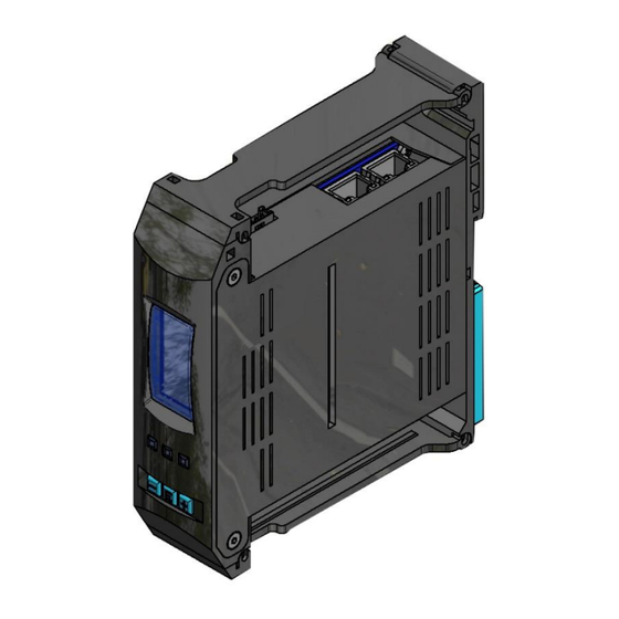
- Page 12 Installation and Connections 1.2 INTERFACE AND TECHNICAL CHARACTERISTICS PROFIBUS Interface (*) Machine Interface (INPUT) Power Supply Ethernet interface (*) option TS55/TMS Chain Max 10 DIAPER FEEDER devices DIAPER FEEDER Chain 10 TS55/TMS sensors EHERNET/PROFINET interface Figure 2 – Board interface SM-DIN/MULTILOOP..
- Page 13 Installation and Connections Technical Characteristics Power supply voltage 12-15VAC - 24 VDC Maximum absorption 200 mA Max Protection fuse (Board protection) Protection fuse (sensors supply) 0.3 A 125 VAC STOP output (normally open contacts) 1 A 30 VDC 0 – 24 VDC Inputs VIL Max 1.2 VDC VIH Min 5 VDC...
- Page 14 Installation and Connections 1.3 ELECTRICAL PANEL TOPOGRAPHIC VIEW PROTECTION MAIN SM-DIN/MULTILOOP/ETH FUSES SWITCH START/STOP RELAY Figure 3 - Topographic View of Electrical box SM-DIN/MULTILOOP.. - 1.4 -...
- Page 15 Installation and Connections xxx= ETH (Ethernet/IP) y=M (Single phase) MATRIX TOUCH DIAPER xxx= PFN (Profinet) y=T (Three phase) connection TMS/TS55 connection Connection of DIAPERFEEDER devices 110/220 or 380/480 Vac Start / Stop / power cable Alarm, etc signal cable Figure 4 - Electrical box SM-DIN/MULTILOOP..
- Page 16 Installation and Connections 1.4 INTERCONNECTION DIAGRAM Figure 5 - Electrical box -MCC3/MCFB/ETH/T interconnection diagram (es. Three phase with ethernet comunication protocol) SM-DIN/MULTILOOP.. - 1.6 -...
- Page 17 Installation and Connections 1.5 APPLICATION EXAMPLE – 4 POSITIONS –ETHERNET IP AND PROFINET NETWORK Figure 6 - Application diagram 4 positions MCC system 3L SM-DIN/MULTILOOP.. - 1.7 -...
- Page 19 Operating Instructions...
- Page 21 Installation and Connections 2.1 BOARD OPERATION All the operations such as Configuration, Operating Parameter Setting, Data and Error display etc. can be managed by the Operator in quick and intuitive way, directly on the SM-DIN/MULTILOOP.. Board. 2.2 NAVIGATION THROUGHOUT THE DISPLAY WINDOWS Display Machine status indication LEDs...
- Page 22 Installation and Connections 2.4 SYMBOLS SHOWN ON LCD Indicates that the device and sensor identification has been executed and the CONTROL system is in control status PROGRAM Indicates that the operating parameter programming by the User is in progress Indicates that the communication with TS55/TMS sensors is active Indicates that the communication with Diaper Feeder devices is active Indicates the exclusion signal status (ON = exclusion activated) 2.5 MENU STRUCTURE...
- Page 23 Installation and Connections IP CONFIGURATION SETTING → BOARD SETUP IP ADDRESS Enter the BOARD SETUP menu Select ADDRESS. To set DHCP SERVER ON DHCP SERVER ON The machine PLC automatically assigns the following parameters: IP address, subnet mask, default gateway to the Board DHCP SERVER OFF The User can manually configure: IP address, subnet...
- Page 24 Installation and Connections Note: on PROFINET PLC integration it is necessary to set for each SMDIN board a “node name” for a correct communication inside the network (*) This is a service parameter used for the communication with the software. Generally it is not necessary to change it. TS55/TMS SENSORS AND DIAPER FEEDER DEVICES IDENTIFICATION →...
- Page 25 Installation and Connections b) The display of just numbered device shows the assigned number. c) the field on the Board display increases by 1. Repeat the above procedure for all connected DIAPER FEEDER devices 3 sec to confirm and go back to BOARD SETUP menu HTP SENSOR IDENTIFICATION...
- Page 26 Installation and Connections at the end of the procedure to go back to BOARD SETUP menu The WRK PARAMETERS – HTP SENSORS menu will be different, depending on the CUBE or CUBE 2-3 selection. ACTD DEVICES IDENTIFICATION (Only for service/optional devices) →...
- Page 27 Installation and Connections MSC DEVICES IDENTIFICATION (Only for service/optional devices) → BOARD SETUP IDENTIFY MSC IDENTIFY Enter the BOARD SETUP menu Select IDENTIFY. Select MSC IDENTIFY. To increase/decrease the value to confirm and go to next parameter 3 sec To move from one parameter to the other To increase/decrease the value.
- Page 28 Installation and Connections LOOP MODE → BOARD SETUP LOOP MODE Enter the BOARD SETUP menu. Select LOOP MODE. To set the system operation mode. ONELOOP DUOLOOP MULTILOOP Single sensor Second sensor Tension control and Tension control Tension control speed features 3 sec to go back to BOARD SETUP...
- Page 29 Installation and Connections I/O CONFIGURATION → BOARD SETUP I/O CONFIG Enter the BOARD SETUP menu. Select CONFIG. To change the parameter value. (NO = Normally Open; NC = Normally Closed) To go to next parameter Currently, the only signals used by the application are: RUN/STOP (exclusion signal), OUT STOP1...
- Page 30 Installation and Connections EXCLUSION SIGNAL CONFIGURATION → BOARD SETUP EXCL.MODE Enter the BOARD SETUP menu. Select EXCL.MODE. To change the parameter value The exclusion signal is activated by field Bus or PLC The exclusion signal is activated by a digital I/O line of the machine AUTO The exclusion signal is activated in automatic mode according to the yarn feeding speed (to be used only in case of unavailability of BUS...
- Page 31 Installation and Connections DF DISPLAY CONFIGURATION → BOARD SETUP DF DISPLAY Enter the BOARD SETUP menu. Select DF DISPLAY To change the DIAPERFEEDER display orientation from NORMAL FLIP mode. To select the parameter of the next position 3 sec to confirm and go back to BOARD SETUP menu DF ENDSCALE CONFIGURATION...
- Page 32 Installation and Connections SMART MATRIX CONFIGURATION → BOARD SETUP SMART MATRIX Enter the BOARD SETUP menu. Select SMART MATRIX. To change the parameter value does not allow the operator to program the style parameters by means of the Matrix Touch terminal allows the operator to program the style parameters by means of the Matrix Touch terminal 3 sec...
- Page 33 Installation and Connections BUS MODE (Debug/Service option) → BOARD SETUP BUS MODE Enter the BOARD SETUP menu. Select BUS MODE To change the parameter value Standard Buffer size Extended Buffer size for dedicate speed detection data buffer (additional communication bytes are enabled, see dedicated SMDIN Communication Protocol) 3 sec to confirm and go back to...
- Page 34 Installation and Connections BUS WARNING → (Debug/Service option) BOARD SETUP BUS WARNING Enter the BOARD SETUP menu. Select BUS WARNING to go back to BOARD SETUP menu Enable warning related to wrong communication with PLC and SM- Disable warning related to wrong communication with PLC and SM- DIN (default) 3 sec to confirm and go back to...
- Page 35 Installation and Connections DEVICE UPDATE → (Debug/Service option) BOARD SETUP DEVICE UPDATE Enter the BOARD SETUP menu. Select DEVICE UPDATE to choose which device from TS55 to ACTD need to update to confirm the device from TS55 and ACTD to update SET POINT →...
- Page 36 Installation and Connections EXCLUSION TENSION → WRK PARAMETERS EXC TENSION Enter the WRK PARAMETERS menu. Select TENSION. The exclusion tension is the tension kept by the sensors with machine stationary. To change the parameter value [12 cN … 1000 cN] To go to next page 3 sec to confirm and go back to...
- Page 37 Installation and Connections OUTPUT SPEED SETTING → (Only if LOOP MODE = MULTILOOP) WRK PARAMETERS SPEED SETPOINT Enter the WRK PARAMETERS menu. Select SPEED SETPOINT. To change the parameter value [50 m/M … 999 m/M] or AUTO The system set as setpoint the average output speed The system set as setpoint the value received from PLC through software integration logic 3 sec...
- Page 38 Installation and Connections TENSION LIMIT → WRK PARAMETERS TENSION LIMIT Enter the WRK PARAMETERS menu. Select TENSION LIMIT: it indicates the tension variation percentage allowed in order to reach the speed setpoint. To change the parameter value [1 % … 100 %] 3 sec to confirm and go back to WRK PARAMETERS...
- Page 39 Installation and Connections GAIN BALANCE → GAIN BALANCE WRK PARAMETERS Enter the WRK PARAMETERS menu. Select GAIN BALANCE. To change the parameter value This parameter allows you to set a different system reactivity depending on the tension value. > 0: the system is more reactive when it has to follow a tension which is rising.
- Page 40 Installation and Connections TENSION DROP → (Only for ACTD optional devices) WRK PARAMETERS TENS DROP Enter the WRK PARAMETERS menu. Select TENSION DROP. To change the parameter value [1% … 99%] 3 sec to confirm and go back to WRK PARAMETERS menu DF MIN TENS →...
- Page 41 Installation and Connections DF RAMP UP → WRK PARAMETERS DF RAMP UP Enter the WRK PARAMETERS menu. Select DF RAMP UP To change the parameter value [1 … 1000 ms] available for each single position 3 sec to confirm and go back to WRK PARAMETERS menu DF RAMP DOWN...
- Page 42 Installation and Connections DISABLE DEVICE → WRK PARAMETERS DISABLE DEVICES Enter the WRK PARAMETERS menu. Select DISABLE DEVICES. To change the parameter value This parameter allows to disable DIAPERFEEDERs or TMS/TS55 in case of issues with specific device or for special configurations ON = device enabled device disabled...
- Page 43 Installation and Connections PFD GAIN → WRK PARAMETERS PFD PARAMETERS → PFD GAIN Enter the WRK PARAMETERS menu. Select PFD PARAMETERS To change the parameter value for each single position when “OFF” the PFD device is disabled; when enabled it controls the Prefeeder device Gain. Default value is 5. Decreasing the parameters is decreased the system reactivity OFF = PFD device enabled...
- Page 44 Installation and Connections To change the parameter value [1 … 1000 cN] 3 sec to confirm and go back to WRK PARAMETERS menu PFD STRETCH RANGE → WRK PARAMETERS PFD PARAMETERS → PFD STRETCH RANGE Enter the WRK PARAMETERS menu. Select PFD PARAMETERS To change the parameter value for each single position...
- Page 45 Installation and Connections SENSOR CONFIGURATION → WRK PARAMETERS HTP SE SENSORS Enter the WRK PARAMETERS menu. Select HTP SE SENSORS. To scroll the parameter list To enter the parameter To change the parameter value If on BOARD SETUP – HTP SENS IDENTFY menu you have selected CUBE 2-3:...
- Page 46 Installation and Connections TMS/TS55 SENSOR OFFSET TMS OFFSET (The following example refers to a configuration with TMS sensors) TS55 OFFSET Enter the TMS OFFSET menu. To enter the parameter change. To change the range of sensors for which the offset shall be executed (*) 3 sec to confirm the offset procedure on the selected sensors...
- Page 47 Installation and Connections TENSION GRAPH DISPLAY TENSION GRAPH Enter the TENSION GRAPH menu. Displayed sensor/device number The graph bar displayed shows the trend of the tension detected on TMS sensors and Diaper Feeder devices. The upper part of the screen shows the numbers of the positions connected (4 on this example).
- Page 48 Installation and Connections To zoom the graph. 3 sec to go to main menu BOARD INFORMATION → BOARD SETUP BOARD INFO Enter the BOARD SETUP menu. Select BOARD INFO. = firmware version loaded on the device To go to next page MAC ADDRESS = unique number associated with the Ethernet interface of the Board...
- Page 49 Installation and Connections 2.6 MESSAGES/ERRORS OF THE SM-DIN/MULTILOOP.. BOARD Communication error (TS COM ERR, DF COM ERR, …) Error on a Diaper Feeder device. Diaper Feeder device locked (the button on the device has been pressed). Door open. Spool-holder carriage not correctly inserted (Matrix Cube 2 or Matrix Cube Left spool exhausted (Matrix Cube 2 or Matrix Cube 3).
- Page 50 Installation and Connections TS55/TMS sensor and Diaper Feeder device identification in progress. This message appears when the identification is executed from PC or Matrix Touch terminal. Diaper Feeder device identification in progress. This message appears when the identification is executed from PC or Matrix Touch terminal.
- Page 51 Installation and Connections 2.7 FUNCTIONS AND FIRMWARE VERSION DETAILS MTX/TOUCH/DIAPER & Firmware Item Available functions MTX2/TOUCH/DIAPER version Compatible version First release Modifications on Communication Protocol (refer to dedicate documentation) Generic Optimization and bug fix Modifications on Communication Protocol (refer to dedicate documentation) Alarm/Warnings Optimization Speed reading and spool change Optimization...
- Page 52 Installation and Connections Introduction of “THREAD-UP” function on MATRIX TOUCH panel Introduction of “MOTION” control for TMS sensors Generic Optimization and bug fix Modifications on Communication Protocol (refer to dedicate documentation) Added new alert of “NO RUN “alarm (specific for Mask application) Corrected error of warning/error assignment for some 1.0.32...
- Page 53 Installation and Connections IS3F/HTP/SE logic modification to keep track of active spool side Sequence reset and descriptor changes on HMS board Management of PFD parameters from SMDIN, Matrix Touch Diaper panel and PLC communication protocol Independent parameters management for gain and others Firmware version reading of PFD, TS55/TMS (from MTX- TOUCH) and ETHERNET/PROFINET interface board (from SMDIN)
- Page 54 DF display. Added Function for DF and TMS led blink green-red as the position is in alarm, only for alarms generated by BTSR local logic (enable-disable available in SMDIN menu) TMS led is set red when position is disabled...
- Page 55 DISTRIBUTOR BTSR International S.p.A. Via S. Rita 21057 OLGIATE OLONA (VA) Tel. 0331-323202 Fax 0331-323282 Internet: www.btsr.com REV. 3.1 – 12/24...
Need help?
Do you have a question about the SM-DIN/MULTILOOP/ETH and is the answer not in the manual?
Questions and answers