
Summary of Contents for LGL KYC TOUCH
- Page 1 MANUALE DI ISTRUZIONE INSTRUCTION MANUAL NOTICE D'INSTRUCTION BEDIENUNGSANLEITUNG MANUAL DE INSTRUCCION EL KİTABI 取扱説明書...
- Page 2 Scope of supply: Design, manufacture and after sales service of yarn and weft feeders, measuring winders, stands, creels and oil systems for textile machinery. TRADUZIONI DELLE ISTRUZIONI ORIGINALI. TRANSLATION OF THE ORIGINAL INSTRUCTIONS. TRADUCTIONS DES INSTRUCTIONS D’ORIGINE. ÜBERSETZUNG DER ORIGINALANLEITUNGEN. TRADUCCIÓN DE LAS INSTRUCCIONES ORIGINALES.
- Page 3 Doc. no.: MAN/KYC TOUCH Rev. 0 L.G.L. Electronics is gratified by your choice and thanks you for the preference communication interface INSTRUCTION MANUAL ISSUED BY: Service Date: 04/1 1/2024 Manager APPROVED BY: Technical Date: 04/1 1/2024 Manager...
- Page 4 WARNINGS Power supply • Use only the cable with custom connector and power the device according to the manufacturer’s instructions; • Do not make connections with wet hands; • Make sure the cable and/or connector are not damaged before use; •...
- Page 5 Declaration of conformity The company LGL ELECTRONICS S.P.A. with registered office in Via Ugo Foscolo, 156 – 24024 Gandino (BG), as manufacturer, declares under its own responsibility, that the product Brand LGL Model: KYC Touch, is operating with the following parameters: •...
- Page 6 INDEX GENERAL FEATURES MAIN SCREEN Machine in run state (main screen background color is green) Machine in stop state (main screen background color is red) FEEDERS IN ALARM READ/WRITE PARAMETERS Parameter change Arameter for feeders in the selected group Change parameter’s value Create/manage groups Groups associations SMART UTILITY FUNCTION...
- Page 7 INDEX KLS FUNCTION KLS function with belt sensor YCM FUNCTION (YARN CONSUMPTION) 10.1 YCM: feeders in group 10.2 Yarn settings 10.3 YCM general settings 10.4 Belt feeder settings 10.5 YCM report save on USB pen GRAPH OF PARAMETERS (SYF) SYNCHRONOUS YARN FEEDING FUNCTION 12.1 SYF tuning 12.2...
-
Page 8: General Features
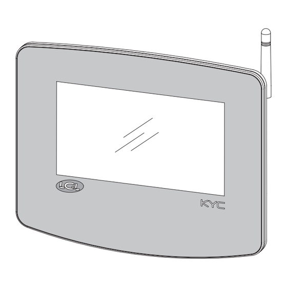
1 - GENERAL FEATURES The KYC device is a communication interface that is connecting the user to the yarn feeders’ system. It is made by a 7 inches display and by some connectors for I/O devices. Fig. 1 RPMF Sensor 2 Ethernet RPMF Sensor 1 Encoder... - Page 9 1 - GENERAL FEATURES Intended uses: The KYC device is a communication interface that is connecting the user to the yarn feeders’ system. It is made by a 7 inches display and by some connectors for I/O devices. Unintended uses: Unintended uses are all uses not explicitly indicated in Intended uses, in particular: - electrical power supply different from the one specified - use of the machine in an explosive atmosphere.
- Page 10 1 - GENERAL FEATURES Technical features: • Dimensions (W x H x D): 230x180x48 (mm) • Weight: 800 g • Power supply: 48V – 60V DC //Current limit 1A (fuse) Operation and storage conditions: • Operating temperature: +10°C to +40°C •...
- Page 11 1 - GENERAL FEATURES Ports and interfaces: MAIN Power, 3 isolated CANBUS, Run, Round pulse, Stop, Inverter Speed, Optional In/Out Signals 1 LAN port via RJ45 socket (standard Ethernet 10-100 Base-T) 1 USB host controllers (version 2.0) 1 Micro USB BELT SENSORS 2 Molex 4p Belt sensors connectors ENCODER...
-
Page 12: Main Screen
5= Timer (It tells from how long the machine is running or it is standing. It resets when the machine changes state RUN-STOP). 6= Number of LGL POSITIVE feeders (TWIN or SPIN) connected. 7= Smart Utility function (see chapter 5). - Page 13 2 - MAIN SCREEN 8= Open stored configuration files. 9= Information about device (see chapter 6). 10= Access level (User or Advanced. Icon 10 is USER. See chapter 7). 1 1= General settings (see chapter 8) 12= Page change icon. 13= YCM function (see chapter 10).
- Page 14 2 - MAIN SCREEN 2.2 MACHINE IN STOP STATE (MAIN SCREEN BACKGROUND COLOR IS RED) Pic. 5 1= Negative feeder ID in alarm with short alarm string. 2= Positive feeder ID in alarm with short alarm string. 3= Alarm detail (see chapter 2).
- Page 15 3 - FEEDERS IN ALARM The alarm comes out on the screen as in the following picture: Pic. 6 Pressing and then , picture 7 appears. A list of all feeders in alarm shows up. Press each button to have more information. Pic.
- Page 16 4 - READ/WRITE PARAMETERS From main screen (picture 3) press icon: Pic.8 On this page you can see, for each group of feeders, 5 parameters. The reported value is the one read by the first feeder of each group. 1= Press the parameter’s name or the “Select” button to change the viewed parameter (see chapter 4.1) 2= Press group button to view information for each feeder of that group (see chapter 4.2) 3= Press the button with the value to change the parameter value for all feeders in the...
-
Page 17: Parameter Change
4 - READ/WRITE PARAMETERS 4.1 PARAMETER CHANGE On the screen of picture 8 press the parameter’s name or “Select”: Pic. 10 All the parameters available in the group will appear. Press on parameter button, right side a description of the parameter appears. - Page 18 4 - READ/WRITE PARAMETERS 4.2 PARAMETER FOR FEEDERS IN THE SELECTED GROUP On the screen of picture 8 press group button: Pic. 11 1= Press to move among the groups. 2= Press the button with the parameter name or “Select” to change the parameter to view. 3= Press the button to change the parameter on the single feeder or on all feeders in the group.
- Page 19 4 - READ/WRITE PARAMETERS 4.3 CHANGE PARAMETER’S VALUE Press the button number 3 in picture 8. This is related to one group and the following picture will appear: Pic. 12...
- Page 20 4 - READ/WRITE PARAMETERS Press the button with the value to change the value on one feeder, and the following picture will appear: Pic. 13 1= Feeder number (Pic 13) or group name (Pic 12). 2= It Is visible only if you are viewing a specific group. If selected, the parameter value will change for all feeders in the group.
- Page 21 4 - READ/WRITE PARAMETERS 4.4 CREATE/MANAGE GROUPS From parameters screen (picture 8) press icon: Pic. 14 1= Insert the name of the new group and press to add it in the list. 2= List of created groups To delete or rename a created group, press and hold the name of the group in the list 2.
- Page 22 4 - READ/WRITE PARAMETERS The following picture appears: Pic. 15 It is possible to modify the group name. Confirm with Cancel the group by pressing As soon as all groups have got their names, press to continue with the next step, which consists in associating each feeder with its group (4.5).
- Page 23 4 - READ/WRITE PARAMETERS 4.5 GROUPS ASSOCIATIONS Picture 16 appears: Pic. 16 1= Present group name to perform association. Tap on the feeder square to associate the feeder to the group. When the feeder is associated, its square takes a strong color (feeders in the same groups will have the same color).
- Page 24 5 - SMART UTILITY FUNCTION From main screen (picture 3) press icon: Pic. 17 1= Press to select the group of feeders to deal with. 2= Offset command (see chapter 5.1). 3= Alarm reset command: Reset alarm on selected devices. 4= Yarn winding command: only on SPIN and TWIN feeders.
- Page 25 5 - SMART UTILITY FUNCTION 5.1 OFFSET This procedure is related to devices equipped with tension sensor. To be made when by removing the yarn from the tension sensor, the read tension is not zero. Press “Offset” button: Pic. 18 There are 4 buttons, execute the command written in each button and then press First button is valid only on positive feeders TWIN and SPIN.
- Page 26 6 - INFORMATION From main screen (picture 3) press icon: Pic. 19 In this screen the information about device software and hardware is provided. The icons on the bottom bar are described in the related chapter: = Diagnostic page (see chapter 6.1) = KYC firmware update (see chapter 6.2)
-
Page 27: Diagnostic Page
The KYC uses the Encoder with TWIN feeders to handle their yarn consumption. Sensor 1A, 1B, 2A, 2B: These concern the two LGL-RPMF sensors (Chapter 9.1 and 10.4). The signal blinks at each turn of the wheel installed on the belt. - Page 28 6 - INFORMATION 6.2 KYC FIRMWARE UPDATE Copy file “KYCTouch4.XX.srec” and the “FILE” folder in the USB root of a USB pen. Insert the USB pen into the KYC device (pic 21): USB Port Pic. 21...
- Page 29 6 - INFORMATION From main screen, press and then Pic. 22 Press “Select folder” to select the USB root. Pic. 23...
- Page 30 6 - INFORMATION Select file “KYCTouch4.XX.srec” and press to copy the file on the KYC device. A green bar shows the copy in progress. At the end the green bar reaches 100% and it disappears. An icon with thunder shape appears . Pic.
-
Page 31: Access Level
7 - ACCESS LEVEL This function allows the operator to set a password to modify parameters on the KYC screen. Two user type have been created: BASE USER and ADVANCED USER. It is possible to create a password for each user. BASE USER can only display information ADVANCED USER can display and modify parameters. - Page 32 7 - ACCESS LEVEL To set the password, press on icon ( Pic. 26 ): Pic. 26 Press “Select user” and choose ADVANCED USER, insert password and press icon. First time do not write anything in the “old password” field. Important: keep the password in a safe place.
-
Page 33: General Settings
8 - GENERAL SETTINGS From main screen (picture 3) press icon: Pic. 27 1= Press to change unit of measure. 2= Network settings (see chapter 8.1) 3= Date and clock settings 4= Brightness and sleep time settings 5= Send file to USB external device. Select the file to send and press to send it to a USB key device. -
Page 34: Network Settings
8 - GENERAL SETTINGS 8.1 NETWORK SETTINGS Press icon: Pic. 28 Modify settings and press to confirm. 1= Press to scan available access points. 2= Press to reset to default network settings. Press to confirm. - Page 35 (LGL RPMF sensor): Pic. 29 1= Move slide to change KLS “Time filter” (default value 3seconds). This is the time the machine takes to reach production speed.
- Page 36 Picture 30 shows one LGL-RPMF sensor to be installed on a belt. The sensor has two wheels, and the system handles maximum two sensors. Wheel B Wheel A Pic. 30 Pic. 31 a. Connect the LGL-RPMF to the connector for the LGL- RPMF sensor 1 (see picture 32) . The KYC will recognize the sensor automatically.
- Page 37 The values in the pictures are the default ones, and they are OK in most cases. NOTE: This function is enables only on LGL-RPMF sensor 1. Please make sure that the belt is turning the lower wheel, because the signal is taken form the lower wheel (the Wheel A in picture 30).
- Page 38 10 - YCM FUNCTION (YARN CONSUMPTION) From main screen (picture 1) press icon: Pic. 33 1= Machine revolution Counter 2= Complete pattern revolutions. 3= List of feeders’ groups. Press on each group button to view data for the feeders in each group (see chapter 10.1) 4= Yarn settings for each group.
- Page 39 Belt feeders’ settings in chapter 10.4 are necessary in case belt driven feeders are installed on the machine. In this case the system will provide the yarn consumption information of the belt driven feeders together with the LGL devices. Once the system has been filled with all information, press button (number 8 in picture 33) to start the calculation.
- Page 40 10 - YCM FUNCTION (YARN CONSUMPTION) 10.2 YARN SETTINGS In Picture 33 press the button next to the group name to insert yarn information: Pic. 35 Insert yarn setting for the feeders in the selected group (in this example “group 1”): yarn type, yarn count and measure unit.
- Page 41 10 - YCM FUNCTION (YARN CONSUMPTION) 10.3 YCM GENERAL SETTINGS From YCM main screen (picture 33) press icon: Pic. 36 Insert machine revolution and machine needles to calculate YCM. Information about machine needles is required to provide the length per 100 needles.
- Page 42 10 - YCM FUNCTION (YARN CONSUMPTION) 10.4 BELT FEEDER SETTINGS The sensor described in this chapter is necessary to calculate the yarn consumption of the belt driven feeders. When belts sensors are installed, the yarn consumption result will include the length, the weight and the weight percentage of the yarn processed by the total amount of belt feeder connected to the same belt.
- Page 43 10 - YCM FUNCTION (YARN CONSUMPTION) From YCM main screen (picture 33) press icon: Pic. 38 Select “Enable A” and/or ”ENABLE B” to enable belt feeders sensors. Each sensor can process up to two belts (A and B) and there are two sensors. The maximum belts number is four.
- Page 44 10 - YCM FUNCTION (YARN CONSUMPTION) For example, enabling sensor number 1 and wheel A: Pic. 39 The yarn consumption result will include the percentages related to the LGL electronic feeders and the percentages related to the belt driven feeders: Pic. 40...
- Page 45 10 - YCM FUNCTION (YARN CONSUMPTION) 10.5 YCM REPORT SAVE ON USB PEN Create and save (to save it press button 10 in picture 33) a YCM report. Insert a USB pen into the pertinent slot on the back of the KYC. USB Port Pic.
- Page 46 10 - YCM FUNCTION (YARN CONSUMPTION) Pic. 42 Press Pic. 43 Press Select folder: a drop-down menu will appear. From the menu select YCM. The YCM files created and saved will be shown on the screen:...
- Page 47 10 - YCM FUNCTION (YARN CONSUMPTION) Pic. 44 Select the file you want to move to USB pen. Here I selected ycm_test1.xml. Once the file has been selected, an arrow appears bottom of the screen. Transfer the file to USB pen by pressing the arrow Pic.
- Page 48 11 - GRAPH OF PARAMETERS From main screen (picture 3) press icon and then Pic. 46 1= Select if you want to see the chart of one feeder only. 2= Select if you want to see the graph of all feeders in the selected group. To select a group, press on “All Feeders”.
- Page 49 11 - GRAPH OF PARAMETERS In the end press icon to display the requested diagram: Pic. 47 1= Parameter shown (Tread in the example). 2= Addresses of the feeders. If the screen is not large enough to fit all feeders, some arrows will appear bottom of the screen to allow a scrolling.
- Page 50 11 - GRAPH OF PARAMETERS The minimum and maximum values of the parameter are shown in picture 48. The blue line shows minimum values, while the red line shown maximum values. This diagram is important for read parameters coming from sensors, like the read yarn tension of this example.
- Page 51 It is not available on any other LGL product. The KYC system must be connected to an encoder synchronized with the machine (available in LGL). The encoder must be connected to the KYC through a connector designed for this purpose. And shown in the following picture:...
- Page 52 12 - SYNCHRONOUS YARN FEEDING FUNCTION (SYF) From main screen (picture 3) press icon: Pic. 50 1= Groups list. Press on each group tab to perform tuning (see dedicated sub-chapter 12.1) 2= Status of synchronous yarn feeding per each group (read only): ENABLED: SYF function enabled.
- Page 53 12 - SYNCHRONOUS YARN FEEDING FUNCTION (SYF) 4= Desired yarn consumption value in cm/revolution. Press to change value. This value can be set through the calibration procedure or it can be written directly in this position. NOTE: After pressing on the value, a new picture appears: Pic.
- Page 54 12 - SYNCHRONOUS YARN FEEDING FUNCTION (SYF) 12.1 SYF TUNING Press a group tab in picture 50 to perform SYF tuning. The tuning sets a constant yarn consumption on the group. See Pic.52: Pic. 52 1= Group selected. 2= Duration of the SYF tuning procedure in number of machine revolutions. 3= When the tuning procedure is over, the yarn consumption value will be shown here.
- Page 55 12 - SYNCHRONOUS YARN FEEDING FUNCTION (SYF) 12.2 SYF IN STANDBY MODE This button appears top right of the main screen if there are Twin feeders equipped with SYF function. Pic. 53 This button allows the operator to stop the SYF function for five revolutions. Twin feeders will work in tension mode during these revolutions.
- Page 56 13 - YARN SPEED CONTROL (YSC) This function is available only on Ecompact and Ecopower feeders DC versions. YSC is a function which allows the feeder equipped with ATTIVO system to control the yarn consumption reference (yarn consumption mode) during plain knitting fabric, and the tension reference (tension mode) during Jacquard patterns.
- Page 57 13 - YARN SPEED CONTROL (YSC) 13.1 YSC TUNING From YSC screen press icon: Pic. 55 1= Press and hold to select or deselect a group (green= yarn consumption mode; grey= tension mode). 2= Change tuning time (default value=15. Normally it is not necessary to change this number). 3= Information: tuning in progress and end of procedure.
- Page 58 13 - YARN SPEED CONTROL (YSC) 13.2 YSC PROCEDURE The pattern must be plain, all feeders of the same group must consume the same amount of yarn. Select the groups which you require to run in yarn consumption mode. If the machine is running, stop it. Press tuning procedure button (number 4 in picture 55) Run the machine and wait until the end of the tuning procedure.
- Page 59 14 - WARPER FUNCTION (ONLY FOR TWIN FEEDERS) This function is available only for Twin units, and it is required when the unit is installed on a warper in order to automatically set the feeders which are involved in the warp production and the ones which will not be used.
- Page 60 14 - WARPER FUNCTION (ONLY FOR TWIN FEEDERS) At the end of the tunin, the result will be shown in the following screen: Pic. 57 1= Feeder in alarm (different from “YrnStanding A” ) 2= Feeder in “Yrn Standing A” 3= Feeder not in alarm 4= Confirm button If the result is as expected, press the confirmation button.
- Page 61 Data Analysis consists in monitoring the feeders’ parameters on the long run, with the target to offer predictive maintenance and suggestions to improve machines efficiency. Remote control allows an LGL technician to check the feeders from remote in case of a problem. From main screen (picture 4) press icon: Pic.
- Page 64 F +39 035 733 146 Via Ugo Foscolo, 156 for any technical or commercial reason without prior lgl@lgl.it 24024 Gandino (BG) notice and without any obligation to supply these www.lgl.it Italy...
Need help?
Do you have a question about the KYC TOUCH and is the answer not in the manual?
Questions and answers