Advertisement
Quick Links
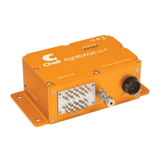
flightDAQ2
Pressure Scanner
Acquisition System
INSTALLATION
AND
OPERATING MANUAL
info@chell.co.uk
e-mail:-
Visit the Chell website at:
http://www.chell.co.uk
Chell Instruments Ltd
Folgate House
Folgate Road
North Walsham
Norfolk NR28 0AJ
ENGLAND
Tel:
01692 500555
Fax:
01692 500088
900203-2.0
Advertisement

Related Manuals for Chell flightDAQ2

Summary of Contents for Chell flightDAQ2
- Page 1 Chell Instruments Ltd Folgate House Folgate Road North Walsham Norfolk NR28 0AJ ENGLAND Tel: 01692 500555 Fax: 01692 500088 flightDAQ2 Pressure Scanner Acquisition System INSTALLATION OPERATING MANUAL info@chell.co.uk e-mail:- Visit the Chell website at: http://www.chell.co.uk 900203-2.0...
- Page 2 Chell Document No. : 900203 Issue 2.0 ECO : 6254 Date: 5 November 2024 Chell’s policy of continuously updating and improving products means that this manual may contain minor differences in specification, components and software design from the actual instrument supplied.
- Page 3 Scanner in calibrate or purge mode........................ 9 Operation of the instrument ....................10 5.1. Powering up the flightDAQ ..........................10 5.2. Connecting to the flightDAQ2 ......................... 10 5.2.1. Connecting to the Webserver ......................... 10 5.2.2. Connecting using the free microDAQX Software................11 5.2.3.
- Page 4 All electrical connections are made to the flightDAQ2 through one connector. To make connecting up easier, Chell can supply a cable and interface with standard connectors on it (RJ45 for Ethernet, D type for CAN and BNC for hardware trigger).
- Page 5 1. Specification 1.1. Power Supply: Line voltage: 24-28 VDC Absolute Max. Line voltage 60V (note the product will not operate >32VDC) Consumption: Max 35VA With a 64-channel scanner: 1.2. CAN specifications: CAN type 2.0B CAN baudrate Configurable (by internal switch) from 1M, 500K, 125K and 100K.
- Page 6 Always switch the power at the power supply source. 2.2. Mounting Holes. The flightDAQ2 has 4 mounting holes suitable for a M6 bolt or stub. It is advisable that all these holes are used in service. 2.3. Earthing It is recommended that the flightDAQ2 is connected to a good ground by grounding the mounting flange, connector shell or via the chassis connection (Pin G).
- Page 7 3. Mechanical Specifications 3.1. Product Mechanical Drawing. Figure 1 Mechanical Drawing A 3D CAD model of the product is available from Chell Instruments Ltd on request. Page 6...
- Page 8 (averaged) as configured within product setup. 3.3.1. Purge Connection The purge gas is connected to the flightDAQ2 next to the electrical connector. The connection may be specified at point of order, select from: 01 5/16-24 SAE o-ring boss 02 1/8”...
- Page 9 In calibrate or purge mode, the pressure transducers are all connected to the calibrate port and the measurement lines are connected to the purge supply valve. Purge gas supplied to the purge port on the flightDAQ2 can then be switched (by using the internal valve) to purge the measurement lines of contaminants and moisture.
- Page 10 4.1. Scanner in run mode. Figure 3 Run-mode pneumatic diagram 4.2. Scanner in calibrate or purge mode. Figure 4 Cal/Purge-mode pneumatic diagram Page 9...
- Page 11 NOTE. If the i/p or subnet mask of the flightDAQ2 is changed, it must be recorded (we recommend that it is written on a new label) as it will not be possible to easily connect to the flightDAQ2 as these are not known. In this case it would be necessary to connect using CAN or to ‘hail’ the device on UDP using the ‘cistat’...
- Page 12 5.2.2. Connecting using the free microDAQX Software. Chell supply the microDAQX software free or charge that can be used to view data and save it to disk. It is available as an installable windows program, a Labview executable or as a VI project. All versions maybe downloaded from the company website without subscription.
- Page 13 6. flightDAQ2 Configuration Webserver 6.1. Introduction. The flightDAQ web Configuration provides the means of setting up, calibrating and demonstrating the flightDAQ unit from a standard PC with an ethernet port and browser. The software is divided by tabs into seven areas of functionality, namely 'Setup’, 'Live data', 'Calibration', 'DTC Information’, ‘Advanced’, ‘Timestamp’, ‘Abs Cal’...
- Page 14 6.2. Common Controls Sidebar Figure 5.1 above shows the first page viewed when navigating to the webserver. The menu at the top allows the user to choose what is visible in the central window, and the sidebar shows information and has a select few commands that are useful regardless of the central page the user is on. The function of the controls on the sidebar is detailed in the subsequent table.
- Page 15 (1 second). This is reverse purging and should be avoided as it can bring contaminants into the flightDAQ2. If purging is to be carried out with pressures on the measurement lines then this routine should NOT be used.
- Page 16 6.3. The 'Setup' Page 6.3.1. Introduction The 'Setup’ page shows all of the flightDAQ's main operating parameters. Setup is divided into different categories by function, and each category is detailed separately in the following. 6.3.2. Data Streaming The ‘Data Streaming’ section allows the user to change settings that affect all three communication protocols, and allows the user to choose the protocol that is to be used, along with the data transfer rate and the number of channels.
- Page 17 6.3.3. TCP Parameters The TCP communication protocol parameters are shown in Figure 5.3. Options control the flightDAQs IP address and subnet mask, in addition to any gateway IP address required. Note flightDAQ's active TCP listening port is fixed at 101. Figure 10 Webserver - TCP Comms group 'IP Address' IP address allocated to flightDAQ on the user's network.
- Page 18 ‘Local IP Address’ Local IP address of the device ‘Local Subnet’ Local subnet of the device ‘Local port’ Local port of the device Remote UDP IP address. Address of remote connection to flightDAQ. If set then the flightDAQ can be set to auto stream data to that remote host on boot up (after initialisation) Remote UDP port.
- Page 19 6.4. 'Live Data' Page Figure 5.6 shows the 'Live Data' page of the webserver, selected for a 32-channel flightDAQ2. Figure 13 Webserver - Live Data Page The live data page is a means to demonstrate the correct operation of flightDAQ and testing the unit's calibration.
- Page 20 6.5. ‘Advanced’ Page The advanced page contains functions that will change the how the flightDAQ acts and how it applies various calculations to its data. 6.5.1. Advanced Data Stream Settings Figure 14 Webserver - Advanced Data Stream Settings Control Function ‘Protocol’...
- Page 21 6.5.1. Advanced communication settings The flightDAQ has several more advanced communication options available, but these features are unlikely to be used by an everyday user and as such should generally be left as default settings. Figure 15 Webserver - Advanced communication settings 'Gateway’...
- Page 22 ‘CAN Power’ Power consumption can be reduced by switching off power to the CAN circuits. Options are On, Auto and Off. On powers the circuit permanently, this is the default and recommended setting. Auto will turn the power off after 1 minute if communications do not occur.
- Page 23 Figure 17 Webserver - function timer settings Control Function ‘Function Timer’ Configures the duration of some automated functions. This value is in seconds and sets the duration the product spends in a special function. Values in the range 5 to 60 are recommended, with 10 seconds being the recommendation.
- Page 24 6.5.3. Filtering The flightDAQ has settings to allow the user flexible control over the data throughput of the device. Averaging options allow the preference of noise reduction over time domain response, the frequency of calibration temperature compensation renewal may be chosen as may be the size of the average (and hence time taken) for the rezero routine.
- Page 25 6.5.5. Span Coefficients Figure 20 Webserver Span Coefficients Control Function ‘1-16’, ’17-32’ & ‘References’ This is a pull-down menu to select the channel data that is displayed, and affected by the operations. ‘Take Span’ This demands the system read the current pressure values and generates a Span Coefficient to have the read value match the stated reference pressure (14.700 psi in this example).
- Page 26 6.6. Timestamp This page allows the user to edit the timestamp settings of the flightDAQ. This timestamp will allow the user to get millisecond level accuracy timestamps on the data packets. If the timestamp is enabled it may have an effect on the maximum transmission rate. The last read Unix time displays the internal flightDAQ time at the last time it was read, the top of the two lines shows the Unix timestamp, and the bottom of the two lines shows the time in a user- friendly format.
- Page 27 The disable command will return the flightDAQ to free-running. Note that stopping the trigger would also return the product to free-run mode. The command structure is fully detailed in document ‘900204 – DAQ Systems programming guide’ available from the http://www.chell.co.uk website but is summarised as follows: Command...
- Page 28 8. Service and Calibration 8.1. Service There are no user serviceable parts inside the instruments. Should any difficulties be encountered in the use of the flightDAQ, it is recommended that you contact Chell Instruments Ltd for advice and instructions. 8.2. Calibration Calibration is recommended on an annual basis and Chell Instruments Ltd provides a fully traceable facility for this purpose.
Need help?
Do you have a question about the flightDAQ2 and is the answer not in the manual?
Questions and answers