
Summary of Contents for T.I.S. A020
- Page 1 RESILIENT SEATED GATE VALVE OPERATING AND MAINTENANCE INSTRUCTIONS FOR SOFT SEATED GATE VALVE Art. A020-A021-A022-A023-A025 IOM130486 - ED12/2017 IOM130486 - ED05/2015...
- Page 2 RESILIENT SEATED GATE VALVE OPERATING AND MAINTENANCE INSTRUCTIONS FOR RESILIENT SEATED GATE VALVE INDEX Pag. 0. General 1. Introduction 2. Safety instructions 3. Identification 4. Storage 5. Transport and lifting 6. Installation 7. Commissioning and operation 8. Maintenance 9. Troubleshooting 10.
-
Page 3: Operation
The main features of T.I.S. valves are set out in the table below. Any deviations from the operating instruc- tions or field of application must be approved in advance by the manufacturer. TECHNICAL DESCRIPTION OF VALVES A020 (F4-PN10), A021 (F4-PN16), A022 (F5-PN10), A023 (F5-PN16), A025 (PN25) VALVE ID. NOMINAL DIAMETER... -
Page 4: Safety Instructions
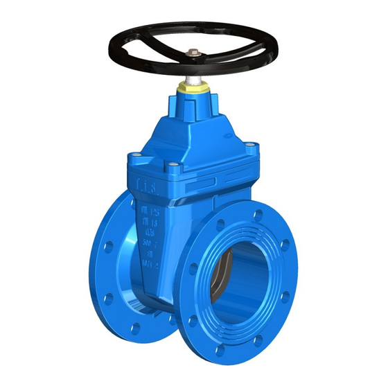
RESILIENT SEATED GATE VALVE 1. Introduction The resilient seated gate valve is an isolating device (for “OPEN-CLOSE” operation) consisting of a flanged body housing, suitable guides formed in the body, and a sliding wedge covered with rubber. The bonnet is screw fixed to the body and houses the necessary mechanisms for opening and closing the wedge. -
Page 5: Transport And Lifting
RESILIENT SEATED GATE VALVE 3. Identification In compliance with EN 19, all the valves have cast markings that indicate nominal diameter (ND), nominal pressure (NP), body material, and the manufacturer's logo. 4. Storage The gate valve should be stored with the wedge slightly open. The elastomeric parts (seals) must be protect- ed against direct sunlight and/or UV light, which could compromise their long-term sealing properties. -
Page 6: Installation
RESILIENT SEATED GATE VALVE 6. Installation Do not remove the protective flange covers until immediately before installing the valve. Before installing, visually examine all functional parts of the valve for damage during transport and storage, and then completely open and close it at least once to check that it is operating perfectly. Check that the ele- ments essential for correct operation, including the wedge and the body guide channels, are free of any for- eign materials. -
Page 7: Commissioning And Operation
RESILIENT SEATED GATE VALVE 7. Commissioning and operation After installation on the pipeline, check that the valve is operating smoothly by moving it through its full range of travel (OPEN – CLOSED) using the control device. Auxiliary equipment (hand crank, electric actuator, etc.) can be used to facilitate this. As standard, the valve is closed by turning the control device in the clockwise direction. -
Page 8: Troubleshooting
RESILIENT SEATED GATE VALVE Replacing the wedge: Depressurize the line where the gate valve is fitted, slightly open the valve and detach the handwheel (or other controls); Unscrew bonnet bolts and remove bonnets; Replace damaged wedge and stem nut and if necessary also change the profile seal; Re-assemble the bonnet and tighten the bolts. - Page 9 RESILIENT SEATED GATE VALVE 10. Disposal and recycling T.I.S. valves are designed and constructed to ensure an extremely long operating life. At the end of their operating life they must be removed/replaced and disassembled with each component separated and sorted according to materials, for example: •...
Need help?
Do you have a question about the A020 and is the answer not in the manual?
Questions and answers