Advertisement
Quick Links
Advertisement

Related Manuals for EASTMAN EM4024TW


Summary of Contents for EASTMAN EM4024TW
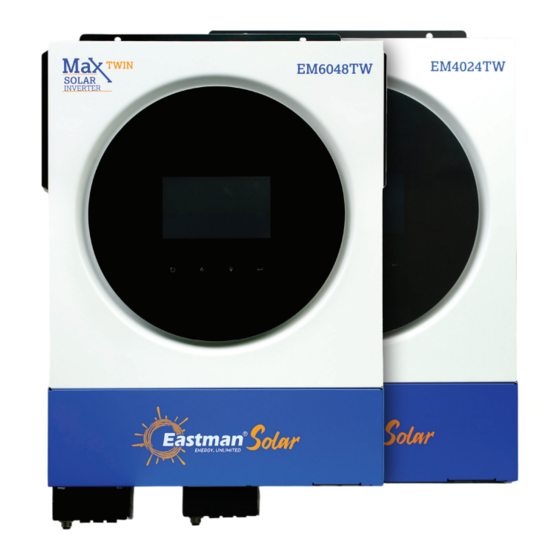
- Page 1 EM4024TW / EM6048TW MAX TWIN SOLAR INVERTER / CHARGER USER MANUAL...
- Page 2 Table of Contents ABOUT THIS MANUAL ............................1 Purpose ................................1 Scope ................................1 SAFETY INSTRUCTIONS ........................... 1 INTRODUCTION ..............................2 Features ................................2 Basic System Architecture ..........................2 Product Overview ............................. 3 Unpacking and Inspection ..........................4 Preparation ..............................4 Mounting the Unit .............................
- Page 3 ABOUT THIS MANUAL Purpose This manual describes the assembly, installation, operation and troubleshooting of this unit. Please read this manual carefully before installations and operations. Keep this manual for future reference. Scope This manual provides safety and installation guidelines as well as information on tools and wiring. SAFETY INSTRUCTIONS WARNING: This chapter contains important safety and operating instructions.
- Page 4 INTRODUCTION This is a multi-function inverter, combining functions of inverter, solar charger and battery charger to offer uninterruptible power support in a single package. The comprehensive LCD display offers user-configurable and easy-accessible button operations such as battery charging current, AC or solar charging priority, and acceptable input voltage based on different applications.
- Page 5 Product Overview 1. LCD display 2. RGB LED bar (refer to LCD Setting section for the details) 3. Touchable function keys 4. Power on/off switch 5. AC input connectors 6. AC output connectors (Load connection) 7. Battery connectors 8. PV connectors 9.
- Page 6 INSTALLATION Unpacking and Inspection Before installation, please inspect the unit. Be sure that nothing inside the package is damaged. You should have received the following items inside of package: Inverter unit Manual software CD RS-232 cable DC Fuse Preparation Before connecting all wirings, please take off bottom cover by removing two screws. When removing the bottom cover, be carefully to remove one cable as shown below.
- Page 7 2*4AWG 33.2 Please follow below steps to implement battery connection: 1. EM4024TW model supports 24VDC system and EM6048TW model supports 48VDC system. Connect all battery packs as below chart. It is recommend to connect minimum of 100Ah capacity battery for...
- Page 8 2. Prepare four battery wires for EM4024TW model and two or four battery wires for EM6048TW model depending on cable size (refer to recommended cable size table). Apply ring terminals to your battery wires and secure it to the battery terminal block with the bolts properly tightened.
- Page 9 2. Remove insulation sleeves for about 10mm for the five screw terminals. 3. Insert AC input wires according to polarities indicated on terminal block and tighten the terminal screws. ) first. Be sure to connect PE protective conductor ( →Ground (yellow-green) L→LINE (brown or black) N→Neutral (blue) WARNING:...
- Page 10 Model Wire Size Cable (mm (max) EM4024TW/EM6048TW 1 x 12AWG 1.2 Nm WARNING: Because this inverter is non-isolated, are accepted: single crystalline, poly crystalline with class A- rated and CIGS modules. To avoid any malfunctions, do not connect any PV modules with possible current leakage to the inverter.
- Page 11 Take the 555Wp PV module as an example. After considering above two parameters, the recommended module configurations are listed in the table below. Solar Panel Spec. SOLAR INPUT Total input Q'ty of panels (reference) Min in series: 2 pcs, max. in series: 11 pcs. power - 555Wp 2 pcs in series...
- Page 12 Communication Connection Follow below chart to connect all communication wiring. BMS communication RS-232 communication to PC USB communication to Serial Connection Please use the supplied serial cable to connect between the inverter and your PC. Install the monitoring software from the bundled CD and follow the on-screen instructions to complete your installation. For detailed software operation, refer to the software user manual on the bundled CD.
- Page 13 Dry Contact Signal There is one dry contact (3A/250VAC) available on the rear panel. It could be used to deliver signal to external device when battery voltage reaches warning level. Unit Status Condition Dry contact port: NC & C NO & C Power Off Unit is off and no output is powered.
- Page 14 OPERATION Power ON/OFF Once the unit has been properly installed and the batteries are connected well, simply press On/Off switch (on the side of the inverter) to turn on the unit. Operation and Display Panel The operation LCD panel, shown in the chart below, includes one RGB LED ring, four touchable function keys and a LCD display to indicate the operating status and input/output power information.
- Page 15 LCD Display Icons Icon Function description Input Source Information Indicates the AC input voltage and frequency. Indicates the PV voltage, current and power. Indicates the battery voltage, charging stage, configured battery parameters, charging or discharging current. Configuration Program and Fault Information Indicates the setting programs.
- Page 16 The ICON flashing indicates the unit with AC output and setting programs 60, 61 or 62 different from default setting. Battery Information Indicates battery level by 0-24%, 25-49%, 50-74% and 75-100% in battery mode and charging status in line mode. When battery is charging, it will present battery charging status.
- Page 17 Indicates setting program 16 “Charger source priority” is selected as “Solar only”. Output source priority setting display Indicates setting program 01 “Output source priority” is selected as “Utility first”. Indicates setting program 01 “Output source priority” is selected as “Solar first”. Indicates setting program 01 “Output source priority”...
- Page 18 LCD Setting General Setting ” After pressing and holding “ button for 3 seconds, the unit will enter the Setup Mode. Press “ ” or “ ” button to select setting programs. Press “ ” button to confirm you selection or “ ”...
- Page 19 Appliances (default) If selected, acceptable AC input voltage range will be within 90-280VAC. AC input voltage range If selected, acceptable AC input voltage range will be within 170-280VAC. AGM (default) Flooded User-Defined If “User-Defined” is selected, battery charge voltage and low DC cut-off voltage can be set up in program 26, 27 and Battery type...
- Page 20 Soltaro battery (only for 48V If selected, programs of 02, model) 26, 27 and 29 will be automatically set up. No need for further setting. LIb-protocol compatible battery Select “LIb” if using Lithium battery compatible to Lib protocol. If selected, Battery type programs of 02, 26, 27 and 29 will be automatically set...
- Page 21 220V 230V (default) Output voltage 240V Maximum utility charging 30A (default) current Setting range is 2A, then from Note: If setting value in program 02 is smaller than 10A to 100A. Increment of that in program in 11, the each click is 10A. inverter will apply charging current from program 02 for utility charger.
- Page 22 Available options for 24V model: Setting range is FUL and from 24V to 29V. Increment of each click is 1V. Battery fully charged 27V (default) Available options for 48V model: Setting range is FUL and from 48V to 58V. Increment of each click is 1V. Setting voltage point or Battery fully charged 54V (default)
- Page 23 Alarm on (default) Alarm off Alarm control Return to default display screen If selected, no matter how (default) users switch display screen, it will automatically return to default display screen (Input voltage /output voltage) after no button is pressed for 1 minute.
- Page 24 Record enable (default) Record disable Record Fault code Available options for 24V model: 28.2V (default) If user-defined is selected in program 5, this program can be set up. Setting range is from 25.0V to 31.5V. Increment of each click is 0.1V.
- Page 25 Available options for 24V model: 21.0V (default) If user-defined is selected in program 5, this program can be set up. Setting range is from 21.0V to 24.0V. Increment of each click is 0.1V. Low DC cut-off voltage will be fixed to setting value Low DC cut-off voltage or no matter what percentage of SOC percentage:...
- Page 26 Available options for 48V model: 58.4V (default) Setting range is from 48.0V to 61.0V. Increment of each click is 0.1V. Battery equalization voltage 60min (default) Setting range is from 5min to 900min. Increment of each click is 5min. Battery equalized time 120min (default) Setting range is from 5min to 900 min.
- Page 27 If “User-defined” is selected in 24V default setting: 21.0V program 05, this setting range is from 21.0V to 31.0V for 24V model. Increment of each click is 0.1V. If “User-defined” is selected in 48V default setting: 42.0V program 05, this setting range is from 42.0V to 60.0V for 48V model.
- Page 28 SOC: 20% (default for lithium If any type of lithium battery battery) is selected in program 05, this parameter value will be displayed in percentage and value setting is based on battery capacity percentage. Setting voltage point or SOC Setting range is from 5% to to restart on the second 100%.
- Page 29 For minute setting, the range is from 0 to 59. Time setting – Minute For hour setting, the range is from 0 to 23. Time setting – Hour For day setting, the range is from 1 to 31. Time setting– Day For month setting, the range is from 1 to 12.
- Page 30 Normal (default) Lighting speed of RGB LED High Power wheel Power cycling RGB LED effect Power chasing Solid on (Default) Solar input power in watt LED lighting portion will be changed by the percentage of solar input power and nominal Data Presentation of data PV power.
- Page 31 Battery capacity percentage LED lighting portion will be (Default) changed by battery capacity percentage. If “Solid on” is selected in #94, LED ring will light up with background color setting in #96. If “Power wheel” is selected in #94, LED ring will light up in 4 levels.
- Page 32 Yellow Green Blue Sky blue (Default) Background color of RGB Purple Other: selected, background color is set by RGB via software. Pink Orange Yellow Green Data Color for RGB LED Sky blue Blue Other: If selected, the data Purple (Default) color is set by RGB via software.
- Page 33 Orange Pink Green Yellow Background color of RGB *Only available when data Blue Sky blue (Default) Presentation of data color is set to Energy source (Grid- PV-Battery). Purple Other: selected, background color is set by RGB via software. Once access this program, it will show “OPP” in LCD. Press “ ”...
- Page 34 Once access this program, it will show “CGP” in LCD. Press “ ” button to select timer setting for charger source priority. There are three timers to set up. Press “ ” or “ ” button to select specific timer option. Then, press “ ”...
- Page 35 USB Function Setting There are three USB function setting such as firmware upgrade, data log export and internal parameter re- Please follow below procedure to execute selected USB function setting. write from the USB disk. Procedure LCD Screen Step 1: Insert an OTG USB disk into the USB port ( Step 2: Press “...
- Page 36 LCD Display The LCD display information will be switched in turn by pressing the “ ” or “ ” button. The selectable information is switched as the following table in order. Selectable information LCD display Input Voltage=230V, Input frequency=50Hz Utility voltage/ Utility frequency PV voltage=300V, PV current=2.0A, PV power=600W PV voltage/ PV current/ PV power Default...
- Page 37 Battery voltage=50.4V, Low DC cut-off voltage=44.0V, Discharging current=48A Battery voltage, charging stage/ Configured battery parameters/ Charging or discharging current L1 output voltage=230V, L1 output frequency=50Hz Default Display Screen Load in VA=2.4kVA, Output frequency=50Hz L1 output voltage/output frequency, load in VA, load in Watt, L2 output voltage/output frequency switch every 5 second Load in Watt=2.4kW, Output frequency=50Hz...
- Page 38 L2 output voltage=230V, L2 output frequency=50 Hz L1 output voltage/output frequency, load in VA, load in Watt, L2 output voltage/output frequency switch output is off. L2 output voltage=0, L2 output frequency=0 Hz every 5 second Default Display Screen Real date Dec 14, 2020. Real date Real time 11:38.
- Page 39 PV energy generation today =888Wh. PV energy generation today PV energy generation this month =8.88kWh. PV energy generation this month PV energy generation this year =88.8kWh. PV energy generation this year Total PV energy generation =888kWh. Total PV energy generation...
- Page 40 Load output energy today =888Wh. Load output energy today Load output energy this month =8.88kWh. Load output energy this month Load output energy this year =88.8kWh. Load output energy this year Total load output energy=888kWh. Total load output energy...
- Page 41 Main CPU version 00050.72. Main CPU version checking Secondary CPU version 00022.01. Secondary CPU version checking Wi-Fi version 00088.88. Wi-Fi version checking...
- Page 42 Operating Mode Description Operation mode Description LCD display Charging by utility and PV energy. Charging by utility. Standby mode Note: No output is supplied *Standby mode: The by the unit but it still inverter is not turned on can charge batteries. yet but at this time, the inverter can charge battery without AC output.
- Page 43 Operation mode Description LCD display No charging. No output is supplied Standby mode by the unit but it still can charge batteries. Grid and PV power are available. Grid is available. Fault mode Note: *Fault mode: Errors are No charging at all no caused by inside circuit matter if grid or PV error or external reasons...
- Page 44 Operation mode Description LCD display Charging by utility and PV energy. Charging by utility. The unit will provide If “SUB” (solar first) is selected as output source output power from the priority and solar energy is not sufficient to provide the Line Mode mains.
- Page 45 Operation mode Description LCD display Power from utility The unit will provide output power from the Line Mode mains. It will also charge the battery at line mode. Power from battery and PV energy. PV energy will supply power to the loads and charge battery at the same time.
- Page 46 Operation mode Description LCD display Power from PV energy only. The unit will provide output power from Battery Mode battery and/or PV power. Faults Reference Code Fault Code Fault Event Icon on Fan is locked when inverter is off. Over temperature Battery voltage is too high Battery voltage is too low Output short circuited.
- Page 47 Warning Indicator Warning Warning Event Audible Alarm Icon flashing Code Beep three times every Fan is locked when inverter is on. second Over temperature None Battery is over-charged Beep once every second Low battery Beep once every second Beep once every 0.5 Overload second Output power derating...
- Page 48 CLEARANCE AND MAINTENANCE FOR ANTI-DUST KIT Overview Every inverter is already installed with anti-dusk kit from factory. This kit also keeps dusk from your inverter and increases product reliability in harsh environment. Clearance and Maintenance Step 1: Please remove the screws on the sides of the inverter. Step 2: Then, dustproof case can be removed and take out air filter foam as shown in below chart.
- Page 49 BATTERY EQUALIZATION Equalization function is added into charge controller. It reverses the buildup of negative chemical effects like stratification, a condition where acid concentration is greater at the bottom of the battery than at the top. Equalization also helps to remove sulfate crystals that might have built up on the plates. If left unchecked, this condition, called sulfation, will reduce the overall capacity of the battery.
- Page 50 SPECIFICATIONS Table 1 Line Mode Specifications MODEL EM4024TW EM6048TW Input Voltage Waveform Sinusoidal (utility or generator) Nominal Input Voltage 230Vac 170Vac±7V (UPS); Low Loss Voltage 90Vac±7V (Appliances) 180Vac±7V (UPS); Low Loss Return Voltage 100Vac±7V (Appliances) High Loss Voltage 280Vac±7V High Loss Return Voltage 270Vac±7V...
- Page 51 <40W <55W Power Limitation EM4024TW When battery voltage is lower than 25V for EM4024TW model and 54V for EM6048TW model, output power will be de-rated. If connected output load is higher than minimum output rated power (3KW for EM4024TW model and 4.6KW for EM6048TW...
- Page 52 Table 3 Charge Mode Specifications Utility Charging Mode MODEL EM6048TW EM4024TW Charging Current (UPS) 100Amp(@V =230Vac) @ Nominal Input Voltage Flooded Battery 29.2 58.4Vdc Bulk Charging Voltage AGM / Gel Battery 28.2 56.4Vdc Floating Charging Voltage 27Vdc 54Vdc Charging Algorithm...
- Page 53 TROUBLE SHOOTING Problem LCD/LED/Buzzer Explanation / Possible cause What to do Unit shuts down LCD/LEDs and buzzer automatically will be active for 3 The battery voltage is too low 1. Re-charge battery. during startup seconds and then (<1.91V/Cell) 2. Replace battery. process.
- Page 54 Appendix I: BMS Communication Installation 1. Introduction If connecting to lithium battery, it is recommended to purchase a custom-made RJ45 communication cable. Please check with your dealer or integrator for details. This custom-made RJ45 communication cable delivers information and signal between lithium battery and the inverter.
- Page 55 PYLONTECH ①Dip Switch: There are 4 Dip Switches that sets different baud rate and battery group address. If switch position is turned to the “OFF” position, it means “0”. If switch position is turned to the “ON” position, it means “1”.
- Page 56 4. Installation and Operation LIO-4805/LIO-4810-150A/ESS LIO-I 4810 After ID no. is assigned for each battery module, please set up LCD panel in inverter and install the wiring connection as following steps. Step 1: Use supplied RJ11 signal cable to connect into the extension port ( P1 or P2 ). Step 2: Use supplied RJ45 cable (from battery module package) to connect inverter and Lithium battery.
- Page 57 Step 5. Turn on the inverter. Step 6. Be sure to select battery type as “LIB” in LCD program 5. If communication between the inverter and battery is successful, the battery icon on LCD display will flash. Generally speaking, it will take longer than 1 minute to establish communication. PYLONTECH Step 1.
- Page 58 Step 4. Turn on the inverter. Step 5. Be sure to select battery type as “PYL” in LCD program 5. If communication between the inverter and battery is successful, the battery icon on LCD display will flash. Generally speaking, it will take longer than 1 minute to establish communication. WECO Step 1.
- Page 59 Step 4. Be sure to select battery type as “WEC” in LCD program 5. If communication between the inverter and battery is successful, the battery icon on LCD display will “flash”. Generally speaking, it will take longer than 1 minute to establish communication. SOLTARO Step 1.
- Page 60 If communication between the inverter and battery is successful, the battery icon on LCD display will “flash”. Generally speaking, it will take longer than 1 minute to establish communication. Active Function This function is to activate lithium battery automatically while commissioning. After battery wiring and commissioning is successfully, if battery is not detected, the inverter will automatically activate battery if the inverter is powered on.
- Page 61 Appendix II: The Wi-Fi Operation Guide 1. Introduction Wi-Fi module can enable wireless communication between off-grid inverters and monitoring platform. Users have complete and remote monitoring and controlling experience for inverters when combining Wi-Fi module with WatchPower APP, available for both iOS and Android based device. All data loggers and parameters are saved in iCloud.
- Page 62 Then, a “Registration success” window will pop up. Tap “Go now” to continue setting local Wi-Fi network connection. Step 2: Local Wi-Fi Module Configuration Now, you are in “Wi-Fi Config” page. There are detailed setup procedure listed in “How to connect?” section and you may follow it to connect Wi-Fi.
- Page 63 Step 3: Wi-Fi Network settings icon to select your local Wi-Fi router name (to access the internet) and enter password. Step 4: Tap “Confirm” to complete the Wi-Fi configuration between the Wi-Fi module and the Internet. If the connection fails, please repeat Step 2 and 3. Diagnose Function If the module is not monitoring properly, please tap “...
- Page 64 2-3. Login and APP Main Function After finishing the registration and local Wi-Fi configuration, enter registered name and password to login. Note: Tick “Remember Me” for your login convenience afterwards. Overview After login is successfully, you can access “Overview” page to have overview of your monitoring devices, including overall operation situation and Energy information for Current power and Today power as below diagram.
- Page 65 Devices Tap the icon (located on the bottom) to enter Device List page. You can review all devices here by adding or deleting Wi-Fi Module in this page. Add device Delete device icon on the top right corner and manually enter part number to add device. This part number label is pasted on the bottom of inverter.
- Page 66 2-4. Device List In Device List page, you can pull down to refresh the device information and then tap any device you want to check up for its real-time status and related information as well as to change parameter settings. Please refer to the parameter setting list.
- Page 67 【Battery Mode】Inverter will power the load from the batter with or without PV charging. Only PV source can charge battery. Device Alarm and Name Modification In this page, tap the icon on the top right corner to enter the device alarm page. Then, you can review alarm history and detailed information.
- Page 68 【Rated Information】displays information of Nominal AC voltage, Nominal AC current, Rated battery voltage, Nominal output voltage, Nominal output frequency, Nominal output current, Nominal output apparent power and Nominal output active power. Please slide up to see more rated information. 【History】displays the record of unit information and setting timely. 【Wi-Fi Module Information】displays of Wi-Fi Module PN, status and firmware version.
- Page 69 Battery To set voltage point or SOC percentage to re-start on second (L2) Voltage/SOC output. Turn On L2 Charge Time to To set waiting time to on second (L2) output when the inverter is Turn On L2 back to Line Mode or battery is in charging status. Battery Battery type To set connected battery type.
- Page 70 Over If disabled, the unit won't be restarted after over-temperature fault is Temperature solved. Auto Restart Overload Auto If disabled, the unit won’t be restarted after overload occurs. Restart Buzzer If disabled, buzzer won’t be on when alarm/fault occurred. Enable/disable Turn on or off RGB LEDs Brightness Adjust the lighting brightness...
- Page 71 www.eastmanworld.com | marketing@eastmanworld.com...
Need help?
Do you have a question about the EM4024TW and is the answer not in the manual?
Questions and answers