
Related Manuals for Nibe CLIMATEMASTER Tranquiliy SM Series


Summary of Contents for Nibe CLIMATEMASTER Tranquiliy SM Series
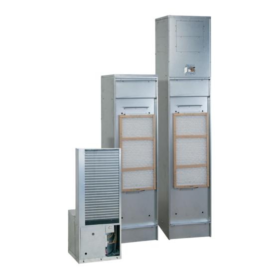
- Page 1 COMMERCIAL TranquiliTy® (SM) VErTiCal STaCK SEriES INSTALLATION, OPERATION & MAINTENANCE MANUAL Part#: 97B0158N01 | Revised: December 13, 2024 Models: SM 06-36 60Hz – R-454B...
-
Page 2: Table Of Contents
TranquiliTy® (SM) VErTiCal STaCK SEriES– iOM Models: Table of Contents 06-36 Model Nomenclature SMS Electrical Data Attentions, Cautions, and Warnings SMT Electrical Data General Information Electrical: Power Wiring Refrigerant System Servicing Electrical: CXM2 Example Wiring Diagram Physical Data Electrical: Low Voltage Wiring Pre-Installation Information Electrical: Thermostat Riser and Cabinet Installation... -
Page 3: Model Nomenclature
TranquiliTy® (SM) VErTiCal STaCK SEriES– iOM Models: Model Nomenclature 06-36 PRODUCT NAME STANDARD S = R-454B Refrigerant S = Standard MODEL TYPE BLOWER MOTOR M = Vertical Stack Chassis Series L = Constant Volume (CV) EC Q = Constant Torque (CT) EC CHASSIS STYLE EXTENDED OPTIONS S = Non-ducted Standard... - Page 4 TranquiliTy® (SM) VErTiCal STaCK SEriES– iOM Models: Model Nomenclature 06-36 PRODUCT NAME SPECIAL OPTIONS S = R-454B S = Standard MODEL TYPE ADDITIONAL CABINET OPTIONS G = Vertical Stack Cabinet Series Supply Air Return Air Outside Air CABINET HEIGHT Open *Recovered Open With Without...
- Page 5 TranquiliTy® (SM) VErTiCal STaCK SEriES– iOM Models: Model Nomenclature 06-36 Riser GROUP RISER LENGTH VALVE PACKAGE (IN INCHES) = Vertical Stack Riser 0 = Drain 7 = 06-12 (Sweat Valve) M = MAKE ITEM 8 = 15-18 (Sweat Valve) 9 = 24-36 (Sweat Valve) RISER STYLE REVISION LEVEL 1 = 80”...
- Page 6 TranquiliTy® (SM) VErTiCal STaCK SEriES– iOM Models: Model Nomenclature 06-36 Return Air Panel G Style ACCESSORY STANDARD VHS RETURN AIR PANEL S = Standard SMS/SMT REVISION LEVEL TYPE G (REMOVABLE) N = Current Revision SMS/SMT (G Panel) STYLE WIDTH A = Standard with ADA Type 1 Tstat Option 1 = 17”...
- Page 7 TranquiliTy® (SM) VErTiCal STaCK SEriES– iOM Models: Model Nomenclature 06-36 Supply Air Grille Nomenclature SUPPLY REVISION LEVEL AIR GRILLE A = Current SPECIAL OPTIONS GRILLE DEFLECTION A = Single Defl ection 0 = Standard (This option is alwas 0 unless a special option is quoted from the factory) B = Double Defl ection C = Double Defl ection and Opposed Damper...
-
Page 8: Attentions, Cautions, And Warnings
TranquiliTy® (SM) VErTiCal STaCK SEriES– iOM Models: Attentions, Cautions, and Warnings 06-36 SAFETY WARNING All refrigerant discharged from this unit must be recovered WITHOUT Warnings, cautions, and notices appear EXCEPTION. Technicians must follow industry accepted guidelines and throughout this manual. Read these items carefully all local, state, and federal statutes for the recovery and disposal of refrigerants. - Page 9 TranquiliTy® (SM) VErTiCal STaCK SEriES– iOM Models: Attentions, Cautions, and Warnings 06-36 CAUTION DO NOT store or install units in corrosive environments or in locations subject to temperature or humidity extremes (e.g., attics, garages, rooftops, etc.). Corrosive conditions and high temperature or humidity can significantly reduce performance, reliability, and service life.
-
Page 10: General Information
TranquiliTy® (SM) VErTiCal STaCK SEriES– iOM Models: General Information 06-36 INSPECTION PREPARE UNITS FOR INSTALLATION AS FOLLOWS: Upon receipt of the equipment, carefully check the shipment against the bill of lading. Make sure all units Compare the electrical data on the unit have been received. - Page 11 TranquiliTy® (SM) VErTiCal STaCK SEriES– iOM Models: General Information 06-36 Presence of fire Extinguisher Refrigerant piping or components are installed in a position where they are unlikely to be exposed If any hot work is to be conducted on the to any substance which may corrode refrigerant refrigeration equipment or any associated parts, containing components, unless the components...
-
Page 12: Refrigerant System Servicing
TranquiliTy® (SM) VErTiCal STaCK SEriES– iOM Models: Refrigerant System Servicing 06-36 REFRIGERANT SYSTEM To maintain sealed circuit integrity, do not install The outlet for the vacuum pump shall not service gauges unless unit operation appears be close to any potential ignition sources, abnormal. - Page 13 TranquiliTy® (SM) VErTiCal STaCK SEriES– iOM Models: Refrigerant System Servicing 06-36 Ensure that the detector is not a potential source of Before attempting the procedure, ensure that: Ignition and is suitable for the refrigerant used. Leak Mechanical handling equipment is available, detection equipment shall be set at a percentage if required, for handling refrigerant cylinders.
- Page 14 TranquiliTy® (SM) VErTiCal STaCK SEriES– iOM Models: Refrigerant System Servicing 06-36 RECOVERY When removing refrigerant from a system, either for shall be available and in good working order. servicing or decommissioning, it is recommended Hoses shall be complete with leak-free disconnect good practice that all refrigerants are removed safely.
-
Page 15: Physical Data
TranquiliTy® (SM) VErTiCal STaCK SEriES– iOM Models: Physical Data 06-36 Tranquility SMS/SMT Series Model Size Compressor (1 Each) Rotary Scroll Factory Charge R-454B (oz) [kg] 18 [0.51]* 24 [0.68] 28 [0.79] 36 [1.02] 38 [1.08] 46 [1.3] 52 [1.47] 50 [1.42] Chassis Air Coil Return Air Filter Dimensions 30 x 14... -
Page 16: Pre-Installation Information
TranquiliTy® (SM) VErTiCal STaCK SEriES– iOM Models: Pre-Installation Information 06-36 STORAGE Equipment should be stored in its original packaging in Keep the cabinet openings and exposed sheet a clean, dry area. Store chassis in an upright position at metal covered until installation is complete and all all times. -
Page 17: Riser And Cabinet Installation
TranquiliTy® (SM) VErTiCal STaCK SEriES– iOM Models: Riser and Cabinet Installation 06-36 DESCRIPTION WARNING To avoid damage from clogged coil surfaces, clogged motor Supply and return risers can be straight, transition ventilation openings, seized fan blades and potential unit failure, DO up, transition down, bottom capped, or top NOT OPERATE UNIT without complete enclosure, supply grille, return air panel and filter in place. - Page 18 TranquiliTy® (SM) VErTiCal STaCK SEriES– iOM Models: Riser and Cabinet Installation 06-36 5. On the next floor up, mark riser at bottom at WARNING 1 inch (25 mm) and 2½ inches (63 mm), drop To prevent electrical shorts and drain pan leaks, assure that screws through slot and position run-outs same as step 2.
- Page 19 TranquiliTy® (SM) VErTiCal STaCK SEriES– iOM Models: Riser and Cabinet Installation 06-36 CABINET INSTALLATION WHEN RISERS ARE CABINET INSTALLATION WHEN RISERS ARE SHIPPED SEPARATELY OR FIELD-PROVIDED ATTACHED (SEE FIGURE 2) Check plans that cabinet is correct for location, Check plans that cabinet is correct for location. cabinet will have label and data plate with The cabinet has a label and dataplate with information, including unit size, diameters of...
-
Page 20: Condensate Piping
TranquiliTy® (SM) VErTiCal STaCK SEriES– iOM Models: Riser and Cabinet Installation 06-36 SUPPLY AND RETURN STACK c. Must securely anchor riser stacks to the building structure with at least one Install a drain valve, shut-off/balancing valves, contact point. Typically at middle floors flow indicators, and drain tees at the base of as needed. - Page 21 TranquiliTy® (SM) VErTiCal STaCK SEriES– iOM Models: Riser and Cabinet Installation 06-36 OPTIONAL FRAME FOR RETURN AIR G PANEL Install studs and drywall using conventional construction methods. Secure the drywall to studs Position the studs in front of the cabinet and install with low-profile, pan-head sheet-metal screws.
- Page 22 TranquiliTy® (SM) VErTiCal STaCK SEriES– iOM Actual area is 3.5313” w x 8.875”h Models: Riser and Cabinet Installation Guides indicate .125” bleed all around 06-36 Figure 2: Riser Placement Riser Setting Detail 9.25” Cabinet Size Valve FPT (235 mm) 06, 09, 12 06-12 1/2”...
- Page 23 TranquiliTy® (SM) VErTiCal STaCK SEriES– iOM Models: Actual area is 7.25” w x 8.875”h Riser and Cabinet Installation 06-36 Guides indicate .125” bleed all around Figure 5: Riser Identification Propress Riser is straight (no swage) Standard Riser Swaged 3” Deep For A Dia.
- Page 24 TranquiliTy® (SM) VErTiCal STaCK SEriES– iOM Models: Actual area is 7.25” w x 8.875”h Riser and Cabinet Installation 06-36 Guides indicate .125” bleed all around Figure 6: Cabinet 9.25” (235 mm) Risers can be in four positions. Supply (S) riser always closest to corner Slit Through...
-
Page 25: Leader/Follower Cabinet Installation
TranquiliTy® (SM) VErTiCal STaCK SEriES– iOM Models: Leader/Follower Cabinet Installation 06-36 Field connect hoses in both cabinets- supply to supply and return to return. (Cabinet supply is closest to corner, chassis supply is on left facing air coil) Note 4 Follower Cabinet Riser Pads (4) Note 4... -
Page 26: Dimensional Data
TranquiliTy® (SM) VErTiCal STaCK SEriES– iOM Models: Dimensional Data 06-36 SMS/SMT Overall, Top Supply, and Front Return Dimensions (inches) Overall Dimensions Top Supply Dimensions Front/ Return Dimensions Model SMT06-12 11.5 2.62 0.67 4.75 20.9 28.4 13.6 56.25 SMT15-18 19.2 11.5 3.87 0.67 4.75... - Page 27 TranquiliTy® (SM) VErTiCal STaCK SEriES– iOM Models: Dimensional Data 06-36 SMS/SMT Overall, Top Supply, and Front Return Dimensions (cm) Overall Dimensions Top Supply Dimensions Front/ Return Dimensions Model SMT06-12 43.18 43.18 165.1 29.21 15.24 6.65 3.81 12.07 15.24 53.09 72.14 34.54 142.88 SMT15-18...
-
Page 28: Standard Sms Cabinet Dimensions
TranquiliTy® (SM) VErTiCal STaCK SEriES– iOM Actual area is 7.25” w x 8.875”h Models: Guides indicate .125” bleed all around Standard SMS Cabinet Dimensions 06-36 ISO BACK ISO FRONT LEFT FRONT RIGHT BACK Notes: All dimensions are in inches (mm). Cabinets have supply air and riser K.O.s, all panels. - Page 29 TranquiliTy® (SM) VErTiCal STaCK SEriES– iOM Actual area is 7.25” w x 8.875”h Models: Guides indicate .125” bleed all around Ducted SMT Cabinet Dimensions 06-36 ISO BACK ISO FRONT LEFT FRONT RIGHT BACK Notes: Dimensions shown are in inches and either mm or cm unless noted otherwise. Style refers to the riser location (digit 9 in Model Nomenclature).
-
Page 30: Sm Hybrid Cabinet Dimensions
TranquiliTy® (SM) VErTiCal STaCK SEriES– iOM Actual area is 7.25” w x 8.875”h Models: SM Hybrid Cabinet Dimensions Guides indicate .125” bleed all around 06-36 1.125” DIA (2) Holes (28.6 mm) 1.62” (41 mm) Front 1.5” (38 mm) 1.5” (38 mm) High Voltage Entrance 2.12”... -
Page 31: Standard And Ducted Cabinet Slot Dimensions And Riser Arrangements
TranquiliTy® (SM) VErTiCal STaCK SEriES– iOM Standard and Ducted Cabinet Slot Dimensions Actual area is 7.25” w x 8.875”h Models: Guides indicate .125” bleed all around and Riser Arrangements 06-36 0.25” to 1” (6 mm to 25 mm) STYLE STYLE TOP VIEWS 4 RA 5 RA... -
Page 32: 80-Inch And 88-Inch Cabinet Configurations
TranquiliTy® (SM) VErTiCal STaCK SEriES– iOM Actual area is 7.25” w x 8.875”h Models: 80-inch and 88-inch Cabinet Configurations Guides indicate .125” bleed all around 06-36 Back/Front/Top Discharge Options – Digit 11 OA, OB OC, OD OE, OF, OG, OH Unit Size Unit Size Unit Size... -
Page 33: Supply Grille Installation
TranquiliTy® (SM) VErTiCal STaCK SEriES– iOM Models: Supply Grille Installation 06-36 SUPPLY GRILLE INSTALLATION Cabinet opening should be sealed to wall. Use canvas-type flex collar or field-supplied duct extension if needed. Refer to the Table 2 below to ensure that the grille size is correct based on the type and size of the supply-air grille. -
Page 34: Typical Cabinet With L Panel Installation
TranquiliTy® (SM) VErTiCal STaCK SEriES– iOM Models: Typical Cabinet with L Panel Installation 06-36 AVHRL .75” Unit Digit 6 06-12 22.1 19.5 55.8 15-18 24.1 21.5 55.8 29.6 26.5 55.9 30-36 29.6 26.5 55.9 Removable 58.50” Inner Panel Fixed Frame NOTICE Frame is attached to studs. -
Page 35: Typical Cabinet With G Panel Installation
TranquiliTy® (SM) VErTiCal STaCK SEriES– iOM Actual area is 7.25” w x 8.875”h Models: Typical Cabinet with G Panel Installation Guides indicate .125” bleed all around 06-36 For surface mounted thermostat, Check thermostat for 2x4 box orientation vertical or horizontal Note 6 R.O. -
Page 36: Typical Cabinet With G Installation - Recessed
TranquiliTy® (SM) VErTiCal STaCK SEriES– iOM Actual area is 7.25” w x 8.875”h Models: Guides indicate .125” bleed all around Typical Cabinet with G Installation – Recessed 06-36 6.0” (152 mm) Note 8, 9 NOTICE Seal Gap four sides Recessed cabinet requires a frame kit. Outside air applications require a Motorized Damper or pre-treated Frame air that is above 45ºF (7ºC) and below 95ºF (35ºC) dry bulb/75ºF (24ºC) -
Page 37: Hybrid Cabinet Slot Dimensions And Riser Arrangements
TranquiliTy® (SM) VErTiCal STaCK SEriES– iOM Hybrid Cabinet Slot Dimensions Actual area is 7.25” w x 8.875”h Models: and Riser Arrangements Guides indicate .125” bleed all around 06-36 0.25” to 1” TOP VIEWS (6 mm to 25 mm) 5.00” (127 mm) STYLE STYLE 4 RA... -
Page 38: Drywall Openings
TranquiliTy® (SM) VErTiCal STaCK SEriES– iOM Models: Drywall Openings 06-36 Figure 7: Cabinet Drywall Openings Figure 8: Cabinet Drywall Openings for Sizes 15-18 and G Panel on Floor for Sizes 24-36 and G Panel with 8-inch Stand One or two layers of drywall. - Page 39 TranquiliTy® (SM) VErTiCal STaCK SEriES– iOM Models: Drywall Openings Actual area is 7.25” w x 8.875”h 06-36 Guides indicate .125” bleed all around Figure 9: Cabinet Drywall Openings for 65-inch Cabinets and G Return-Air Panel One or two layers of drywall. Set studs accordingly.
-
Page 40: Cabinet With G Panel Frame
TranquiliTy® (SM) VErTiCal STaCK SEriES– iOM Models: Cabinet with G Panel Frame Actual area is 7.25” w x 8.875”h 06-36 Guides indicate .125” bleed all around Figure 10: Cabinet with G Panel Frame and Optional Outside Air Duct (Field Fabricated) Field-supplied Grille with Insect Screen Outside Wall... -
Page 41: Water-Loop Heat-Pump Applications
TranquiliTy® (SM) VErTiCal STaCK SEriES– iOM Models: Water-Loop Heat-Pump Applications 06-36 COMMERCIAL WATER-LOOP APPLICATIONS Commercial systems typically include a number of The piping system should be flushed to remove units connected to a common piping system. Any dirt, piping chips, and other foreign material unit plumbing maintenance work can introduce prior to operation (see Piping System Cleaning air into the piping system;... -
Page 42: Ground-Loop Heat-Pump Applications
TranquiliTy® (SM) VErTiCal STaCK SEriES– iOM Models: Ground-Loop Heat-Pump Applications 06-36 Test individual horizontal loop circuits before CAUTION backfilling. Test vertical U-bends and pond loop The following instructions represent industry accepted installation assemblies prior to installation. Pressures of at least practices for closed loop earth coupled heat pump systems. -
Page 43: Water Quality Requirements
TranquiliTy® (SM) VErTiCal STaCK SEriES– iOM Models: Water Quality Requirements 06-36 Table 3: Water Quality Requirements Clean water is essential to the performance and life span of water source heat pumps. Contaminants, chemicals, and minerals all have the potential to cause damage to the water heat exchanger if not treated properly. - Page 44 TranquiliTy® (SM) VErTiCal STaCK SEriES– iOM Models: Water Quality Requirements 06-36 α The ClimateMaster Water Quality Table on Hydrogen Sulfide has an odor of rotten eggs. page 39 provides water quality requirements for If one detects this smell, a test for H S must be coaxial and brazed plate heat exchangers.
- Page 45 TranquiliTy® (SM) VErTiCal STaCK SEriES– iOM Actual area is 7.25” w x 8.875”h Models: Water Quality Requirements Guides indicate .125” bleed all around 06-36 Measuring Earth Ground Resistance for Ground-Water Applications � 0.02 Building Well Casing Ground Rod Ohm meter Measure the earth ground bond using an Ohm meter between the building’s ground rod and the steel well casing.
- Page 46 TranquiliTy® (SM) VErTiCal STaCK SEriES– iOM Actual area is 7.25” w x 8.875”h Models: Water Quality Requirements Guides indicate .125” bleed all around 06-36 Measuring Electrolysis, Voltage, and Current for Ground-Water Applications 300mV Heat Pump Volt Meter Wire Electrode inserted into port for Voltage Measurement Pete’s Port Water in...
-
Page 47: Sms Electrical Data
TranquiliTy® (SM) VErTiCal STaCK SEriES– iOM Models: SMS Electrical Data 06-36 Electrical Data: CT EC Blower Motor Electrical Branch Circuit Rating and Protection Component Compressor No Pump Internal Source Pump Options Rated Voltage Size Voltage Code CT EC Voltage Min/Max Total Total Fuse... -
Page 48: Smt Electrical Data
TranquiliTy® (SM) VErTiCal STaCK SEriES– iOM Models: SMT Electrical Data 06-36 Electrical Data: CT EC Blower Motor Electrical Branch Circuit Rating and Protection Component Compressor No Pump Internal Source Pump Options Rated Voltage Size Voltage Code CT EC Voltage Min/Max Total Total Fuse... -
Page 49: Electrical: Power Wiring
TranquiliTy® (SM) VErTiCal STaCK SEriES– iOM Models: Electrical: Power Wiring 06-36 Figure 11: Single Phase Line Voltage Field Wiring WARNING Disconnect electrical power source to prevent injury or death from Capacitor electrical shock. Contactor -CC CAUTION Use only copper conductors for field installed electrical wiring. Unit terminals are not designed to accept other types of conductors. -
Page 50: Electrical: Cxm2 Example Wiring Diagram
TranquiliTy® (SM) VErTiCal STaCK SEriES– iOM Models: Electrical: CXM2 Example Wiring Diagram 06-36 NOTES: Field Use Only: Transformer wiring is voltage-sensitive. Use layout corresponding to the unit voltage. Typical heat-pump thermostat wiring shown. Refer to thermostat IOM for wiring to the unit. Thermostat wiring must be “Class I”... -
Page 51: Electrical: Low Voltage Wiring
TranquiliTy® (SM) VErTiCal STaCK SEriES– iOM Models: Electrical: Low Voltage Wiring 06-36 THERMOSTAT CONNECTIONS Therefore, LT1 is sensing refrigerant temperature, not water temperature, which is a better indication of The thermostat should be wired directly to the how water flow rate/temperature is affecting the CXM2 or DXM2.5. -
Page 52: Temperature Sensors
TranquiliTy® (SM) VErTiCal STaCK SEriES– iOM Actual area is 3.5313” w x 8.875”h Models: Electrical: Low Voltage Wiring Guides indicate .125” bleed all around 06-36 TEMPERATURE SENSORS 17B0008N05 LT2 Air-Coil Protector Leaving-Air-Temp Sensor (Violet (2) Wires - Harness Six temperature sensors are located on the chassis: (White (2) Wires Connect to to DXM2.5-LT2) DXM2.5-T4) - Page 53 TranquiliTy® (SM) VErTiCal STaCK SEriES– iOM Models: Electrical: Low Voltage Wiring 06-36 REFRIGERANT DETECTION SYSTEM (RDS) FIELD-INSTALLED RDS SYSTEM The function, operation, and required servicing For horizontal systems installed on ceiling plenum measures for the RDS include the following: for non-ducted applications, use the following guidelines to install a refrigerant detection sensor The RDS monitors the status of the refrigerant upstream of the return of the unit:...
-
Page 54: Electrical: Thermostat
TranquiliTy® (SM) VErTiCal STaCK SEriES– iOM Models: Electrical: Thermostat 06-36 THERMOSTAT INSTALLATION Installation of optional wall-mounted WARNING thermostat. The unit can be furnished Zone integrity must be maintained to efficiently control units or groups of with a 24V surface-mounted ACO or MCO units. -
Page 55: Blower Performance
TranquiliTy® (SM) VErTiCal STaCK SEriES– iOM Blower Performance Models: SMS06 06-36 Blower Blower Motor Details External Static Pressure (in. wg) Motor CV EC 1,120 Blower performance data is based on the lowest nameplate voltage setting. Blower performance is based on a wet coil with clean 1-inch filter. Blower performance is based on operating conditions of 80°F DB and 67°F WB. - Page 56 TranquiliTy® (SM) VErTiCal STaCK SEriES– iOM Blower Performance Models: SMS09 06-36 Blower Blower Motor Details External Static Pressure (in. wg) Motor Speed Tap Operation Not Recommended Power (W) Power (W) CT EC 1,000 1,100 1,180 Power (W) 1,010 1,070 1,160 1,240 Power (W) 1,120...
- Page 57 TranquiliTy® (SM) VErTiCal STaCK SEriES– iOM Blower Performance Models: SMS12 06-36 Blower Blower Motor Details External Static Pressure (in. wg) Motor Speed Tap Operation Not Recommended Power (W) 1,050 Power (W) CT EC 1,040 1,130 1,220 Power (W) 1,030 1,110 1,190 1,280 Power (W)
- Page 58 TranquiliTy® (SM) VErTiCal STaCK SEriES– iOM Blower Performance Models: SMS15 06-36 Blower Blower Motor Details External Static Pressure (in. wg) Motor Speed Tap Operation Not Recommended Power (W) Power (W) CT EC Power (W) Power (W) Power (W) Power (W) CV EC Power (W) 1,000...
- Page 59 TranquiliTy® (SM) VErTiCal STaCK SEriES– iOM Blower Performance Models: SMS18 06-36 Blower Blower Motor Details External Static Pressure (in. wg) Motor Speed Tap Operation Not Recommended Power (W) Power (W) CT EC Power (W) 1,000 Power (W) 1,030 1,070 Power (W) Power (W) Power (W) CV EC...
- Page 60 TranquiliTy® (SM) VErTiCal STaCK SEriES– iOM Blower Performance Models: SMS24 06-36 Blower Blower Motor Details External Static Pressure (in. wg) Motor Speed Tap Power (W) Power (W) CT EC Power (W) Power (W) Power (W) Operation Not Recommended Power (W) Power (W) CV EC Power (W)
- Page 61 TranquiliTy® (SM) VErTiCal STaCK SEriES– iOM Blower Performance Models: SMS30 06-36 Blower Blower Motor Details External Static Pressure (in. wg) Motor Speed Tap Power (W) Power (W) 1,000 1,000 CT EC Power (W) 1,140 1,100 1,070 1,030 1,000 1,040 1,060 Power (W) 1,230 1,200...
- Page 62 TranquiliTy® (SM) VErTiCal STaCK SEriES– iOM Blower Performance Models: SMS36 06-36 Blower Blower Motor Details External Static Pressure (in. wg) Motor Speed Tap Power (W) 1,010 1,050 1,090 Power (W) 1,130 1,100 1,080 1,040 1,070 1,110 1,150 1,170 CT EC Power (W) 1,280 1,260...
- Page 63 TranquiliTy® (SM) VErTiCal STaCK SEriES– iOM Blower Performance Models: SMT06 06-36 Blower Blower Motor Details External Static Pressure (in. wg) Motor 1,028 1,118 1,170 1,230 CV EC 1,096 1,192 1,248 1,312 1,100 1,230 1,370 1,490 1,560 1,640 Blower performance data is based on the lowest nameplate voltage setting. Blower performance is based on a wet coil with clean 1-inch filter.
- Page 64 TranquiliTy® (SM) VErTiCal STaCK SEriES– iOM Blower Performance Models: SMT09 06-36 Blower Blower Motor Details External Static Pressure (in. wg) Motor Speed Tap 1,080 1,170 1,260 1,360 Operation Not Power (W) Recommended 1,060 1,160 1,230 1,320 1,390 1,500 Power (W) CT EC 1,230 1,310...
- Page 65 TranquiliTy® (SM) VErTiCal STaCK SEriES– iOM Blower Performance Models: SMT12 06-36 Blower Blower Motor Details External Static Pressure (in. wg) Motor Speed Tap 1,070 1,140 1,230 1,320 1,400 Operation Not Power (W) Recommended 1,140 1,190 1,280 1,370 1,430 1,510 1,580 Power (W) CT EC 1,190...
- Page 66 TranquiliTy® (SM) VErTiCal STaCK SEriES– iOM Blower Performance Models: SMT15 06-36 Blower Blower Motor Details External Static Pressure (in. wg) Motor Speed Tap Operation Not Recommended Power (W) Power (W) 1,040 CT EC Power (W) 1,010 1,070 1,120 Power (W) 1,010 1,050 1,100...
- Page 67 TranquiliTy® (SM) VErTiCal STaCK SEriES– iOM Blower Performance Models: SMT18 06-36 Blower Blower Motor Details External Static Pressure (in. wg) Motor Speed Tap Operation Not Recommended Power (W) 1,030 Power (W) 1,040 1,060 1,090 1,130 1,200 CT EC Power (W) 1,000 1,080 1,110...
- Page 68 TranquiliTy® (SM) VErTiCal STaCK SEriES– iOM Blower Performance Models: SMT24 06-36 Blower Blower Motor Details External Static Pressure (in. wg) Motor Speed Tap Power (W) 1,020 1,080 Power (W) 1,000 1,050 1,100 CT EC Power (W) 1,080 1,120 Power (W) Operation Not Recommended Power (W) 1,005...
- Page 69 TranquiliTy® (SM) VErTiCal STaCK SEriES– iOM Blower Performance Models: SMT30 06-36 Blower Blower Motor Details External Static Pressure (in. wg) Motor Speed Tap 1,000 1,050 1,090 Power (W) 1,040 1,000 1,040 1,090 1,130 Power (W) 1,110 1,080 1,050 1,010 1,070 1,110 1,150 1,180...
- Page 70 TranquiliTy® (SM) VErTiCal STaCK SEriES– iOM Blower Performance Models: SMT36 06-36 Blower Blower Motor Details External Static Pressure (in. wg) Motor Speed Tap 1,020 Power (W) 1,080 1,050 1,020 1,010 1,060 1,090 1,140 1,170 Power (W) 1,220 1,190 1,150 1,130 1,100 1,060 1,030...
-
Page 71: Chassis Pre-Installation
TranquiliTy® (SM) VErTiCal STaCK SEriES– iOM Models: Chassis Pre-Installation 06-36 See Figures 18-21 b. Inspect insulation inside compressor enclosure Check chassis data plate. Verify chassis is correct for rubs from tubing or reversing valve. Adjust for the cabinet. Chassis I.D. sticker should match tubing or RV inward if needed. -
Page 72: Hose Kit And Chassis Installation
TranquiliTy® (SM) VErTiCal STaCK SEriES– iOM Models: Hose Kit and Chassis Installation 06-36 HOSE KIT AND CHASSIS INSTALLATION Figure 22: Return and Supply Shutoff Location (Cabinet Style 2 Riser Back Left) After cabinets are installed, and walls finished remove the filter and front blockoff panel. - Page 73 TranquiliTy® (SM) VErTiCal STaCK SEriES– iOM Models: Hose Kit and Chassis Installation 06-36 Step 3: Attach AHU hoses to the Chassis. Check the Step 4: Chassis Installation - Check condensate pan swivel ends of the hoses (Figure 25). Washers must is free and on 4 rubber grommets.
- Page 74 TranquiliTy® (SM) VErTiCal STaCK SEriES– iOM Models: Hose Kit and Chassis Installation 06-36 Figure 24: Chassis Connections 8. Re-attach the inner panel (8 screws) and filter as shown in the figure below. The chassis must free- float on condensate pan. If inner-panel holes do not align, push chassis further in.
-
Page 75: System Cleaning And Flushing
TranquiliTy® (SM) VErTiCal STaCK SEriES– iOM Models: Startup Preparation 06-36 Flush risers as follows (Refer to Figure 26): WARNING Remove cabinet filter and front inner panel. Save To prevent injury or death due to electrical shock or contact with moving parts, open unit disconnect before servicing unit. these for re-installation after the chassis is installed. - Page 76 TranquiliTy® (SM) VErTiCal STaCK SEriES– iOM Models: Startup Preparation 06-36 Figure 26: Typical Piping Arrangement for Flushing Risers Hose or Piping Connecting Supply and Return Runouts Runouts to Chassis To Waste Supply Riser Return Riser PA G E : 76 P a r t # : 9 7 B 0 1 5 8 n 0 1 | r e v i s e d : D e c e m b e r 1 3 , 2 0 2 4 w w w.
-
Page 77: Controls: Cxm2 And Dxm2.5
TranquiliTy® (SM) VErTiCal STaCK SEriES– iOM Models: Controls: CXM2 and DXM2.5 06-36 CXM2 Communicating Controls For detailed controller information, see the CXM2 Application, Operation, and Maintenance (AOM) manual (part # 97B0137N01). To confirm the controller type of your particular unit, refer to digit 9 on the unit model number and the unit nomenclature diagram found on page 3 of this manual. -
Page 78: Operating Limits And Commissioning Conditions
TranquiliTy® (SM) VErTiCal STaCK SEriES– iOM Models: Operating Limits and Commissioning Conditions 06-36 OPERATING LIMITS COMMISSIONING CONDITIONS Environment – Units are designed for indoor Starting conditions vary depending upon model and installation only. Never install units in areas subject are based upon the following notes: to freezing or where humidity levels could cause NOTES: cabinet condensation (such as unconditioned... - Page 79 TranquiliTy® (SM) VErTiCal STaCK SEriES– iOM Models: Operating Limits and Commissioning Conditions 06-36 Table 6: Operating Limits Table 7: Commissioning Conditions Operating Limits Cooling Heating Commissioning Conditions Cooling Heating Air Limits Air Limits Min. ambient air, DB *10°F [-12°C] *10°F [-12°C] Min.
-
Page 80: Unit And System Checkout
TranquiliTy® (SM) VErTiCal STaCK SEriES– iOM Models: Unit and System Checkout 06-36 SYSTEM CHECKOUT UNIT CHECKOUT BEFORE POWERING SYSTEM, please check the following: Balancing/shutoff valves: Ensure that all isolation † valves are open and water control valves are wired. System-water temperature: Check water †... -
Page 81: Unit Startup Procedures
TranquiliTy® (SM) VErTiCal STaCK SEriES– iOM Models: Unit Startup Procedures 06-36 NOTE: All Pre-Installation, Installation, Unit and System b. Air leaving should be 10 to 25°F (5.5 and 14°C) Checkout steps must be followed and completed before lower than entering air. Check air coil. If the starting unit. -
Page 82: Unit Operating Conditions
TranquiliTy® (SM) VErTiCal STaCK SEriES– iOM Models: Unit Operating Conditions 06-36 Operating Pressure/Temperature tables include the following notes: Airflow is at nominal (rated) conditions Entering air is based upon 70°F (21°C) DB in heating and 80/67°F (27/19°C) in cooling Subcooling is based upon head pressure at compressor service port Cooling air and water values can vary greatly with changes in humidity level Operation of heating mode is not recommended with entering water temperatures above 100°F (38°C) Water Temp... - Page 83 TranquiliTy® (SM) VErTiCal STaCK SEriES– iOM Models: Unit Operating Conditions 06-36 Water Temp Air Temp Entering Water Suction Discharge Discharge LT1 Temp LT2 Temp Super-heat Sub-cooling Cooling Rise/ Cooling Drop/ Water Flow Pressure Pressure Temp ºF ºF ºF ºF Heating Drop Heating Rise Temp ºF PSIG...
- Page 84 TranquiliTy® (SM) VErTiCal STaCK SEriES– iOM Models: Unit Operating Conditions 06-36 Water Temp Air Temp Entering Water Suction Discharge Discharge LT1 Temp LT2 Temp Super-heat Sub-cooling Cooling Rise/ Cooling Drop/ Water Flow Pressure Pressure Temp ºF ºF ºF ºF Heating Drop Heating Rise Temp ºF PSIG...
- Page 85 TranquiliTy® (SM) VErTiCal STaCK SEriES– iOM Models: Unit Operating Conditions 06-36 Water Temp Air Temp Entering Water Suction Discharge Discharge LT1 Temp LT2 Temp Super-heat Sub-cooling Cooling Rise/ Cooling Drop/ Water Flow Pressure Pressure Temp ºF ºF ºF ºF Heating Drop Heating Rise Temp ºF PSIG...
- Page 86 TranquiliTy® (SM) VErTiCal STaCK SEriES– iOM Models: Unit Operating Conditions 06-36 Water Temp Air Temp Entering Water Suction Discharge Discharge LT1 Temp LT2 Temp Super-heat Sub-cooling Cooling Rise/ Cooling Drop/ Water Flow Pressure Pressure Temp ºF ºF ºF ºF Heating Drop Heating Rise Temp ºF PSIG...
- Page 87 TranquiliTy® (SM) VErTiCal STaCK SEriES– iOM Models: Unit Operating Conditions 06-36 Water Temp Air Temp Entering Water Suction Discharge Discharge LT1 Temp LT2 Temp Super-heat Sub-cooling Cooling Rise/ Cooling Drop/ Water Flow Pressure Pressure Temp ºF ºF ºF ºF Heating Drop Heating Rise Temp ºF PSIG...
- Page 88 TranquiliTy® (SM) VErTiCal STaCK SEriES– iOM Models: Unit Operating Conditions 06-36 Water Temp Air Temp Entering Water Suction Discharge Discharge LT1 Temp LT2 Temp Super-heat Sub-cooling Cooling Rise/ Cooling Drop/ Water Flow Pressure Pressure Temp ºF ºF ºF ºF Heating Drop Heating Rise Temp ºF PSIG...
-
Page 89: Coax Water-Pressure Drop
TranquiliTy® (SM) VErTiCal STaCK SEriES– iOM Models: Coax Water-Pressure Drop 06-36 Pressure Drop, PSI PD Added for Model Add for MWV 30°F 50°F 70°F 90°F SM*06 SM*09 SM*12 SM*15 SM*18 SM*24 SM*30 SM*36 w w w. c l i m a t e m a s t e r. c o m P a r t # : 9 7 B 0 1 5 8 n 0 1 | r e v i s e d : D e c e m b e r 1 3 , 2 0 2 4 PA G E : 8 9... -
Page 90: Startup Log Sheet
TranquiliTy® (SM) VErTiCal STaCK SEriES– iOM Models: Startup Log Sheet Startup Log Sheet 06-36 Models: Vertical Stack Series Units TSM, TSl 7300 S.W. 44th Street, Oklahoma City, OK 73179 • Phone: 1-800-299-9747 Installer: Complete Unit and System Checkout and follow Unit Startup Procedures in the IOM. Use this form to record unit information, temperatures, and pressures during startup. -
Page 91: Preventive Maintenance
TranquiliTy® (SM) VErTiCal STaCK SEriES– iOM Models: Preventive Maintenance 06-36 WATER COIL MAINTENANCE AIR COIL (WATER LOOP APPLICATIONS) The air coil must be cleaned to obtain maximum performance. Check once a year under normal Generally water coil maintenance is not needed operating conditions and, if dirty, brush or vacuum for closed loop systems. -
Page 92: Functional Troubleshooting
TranquiliTy® (SM) VErTiCal STaCK SEriES– iOM Models: Functional Troubleshooting 06-36 Fault Htg Clg Possible Cause Solution Check line voltage circuit breaker and disconnect. Check for line voltage between L1 and L2 on the contactor. Main power problems Green Status LED Off Check for 24VAC between R and C on CXM2/DXM2.5. - Page 93 TranquiliTy® (SM) VErTiCal STaCK SEriES– iOM Models: Functional Troubleshooting 06-36 Table continued from previous page. Fault Htg Clg Possible Cause Solution Check power supply and 24VAC voltage before and during operation. Check power supply wire size. Under Voltage Check compressor starting. Need hard start kit? Over/Under Voltage Code 7 Check 24VAC and unit transformer.
- Page 94 TranquiliTy® (SM) VErTiCal STaCK SEriES– iOM Models: Functional Troubleshooting 06-36 Table continued from previous page. Fault Htg Clg Possible Cause Solution Check G wiring at heat pump. Jumper G and R for fan operation. Thermostat wiring Check thermostat wiring at heat pump. Jumper Y and R for compressor operation in test mode.
-
Page 95: Performance Troubleshooting
TranquiliTy® (SM) VErTiCal STaCK SEriES– iOM Models: Performance Troubleshooting 06-36 Symptom Htg Clg Possible Cause Solution Dirty filter Replace or clean. Check for dirty air filter and clean or replace. Reduced or no airflow in heating Check fan motor operation and airflow restrictions. Too high of external static? Check static vs. - Page 96 TranquiliTy® (SM) VErTiCal STaCK SEriES– iOM Models: Performance Troubleshooting 06-36 Table continued from previous page. Symptom Htg Clg Possible Cause Solution Too high of airflow Check fan motor speed selection and airflow chart. High humidity Recheck loads & sizing. Check sensible cooling load and heat Unit oversized pump capacity.
-
Page 97: Wire Harness
TranquiliTy® (SM) VErTiCal STaCK SEriES– iOM Actual area is 7.25” w x 8.875”h Wire Harness Models: Guides indicate .125” bleed all around for 06-12 CV EC with DXM2.5 06-36 Surface Mount Option - Make Connect Here SURFACE BOX ON CABINET 11B0100N15 (30”) Surface Mount Option Only... - Page 98 TranquiliTy® (SM) VErTiCal STaCK SEriES– iOM Wire Harness Actual area is 7.25” w x 8.875”h Models: for 06-12 CT EC with DXM2.5 Guides indicate .125” bleed all around 06-36 Surface Mount Option - Make Connect Here SURFACE BOX ON CABINET 11B0100N15 (30”) Surface Mount Option Only...
- Page 99 TranquiliTy® (SM) VErTiCal STaCK SEriES– iOM Actual area is 7.25” w x 8.875”h Wire Harness Models: for 06-12 CT EC with CXM2 Guides indicate .125” bleed all around 06-36 2 X 4 Surface Mount Option - Make Connect Here SURFACE BOX ON CABINET 11B0100N15 (30”) Surface Mount Option...
- Page 100 TranquiliTy® (SM) VErTiCal STaCK SEriES– iOM Wire Harness Actual area is 7.25” w x 8.875”h Models: for 15-36 CV EC with DXM2.5 Guides indicate .125” bleed all around 06-36 Surface Mount Option - MaKe Connect Here SURFACE BOX ON CABINET 11B0100N15 (30”) Surface Mount Option Only...
- Page 101 TranquiliTy® (SM) VErTiCal STaCK SEriES– iOM Actual area is 7.25” w x 8.875”h Wire Harness Models: Guides indicate .125” bleed all around for 15-36 CT EC with DXM2.5 06-36 Surface Mount Option - Make Connect Here SURFACE BOX ON CABINET 11B0100N15 (30”) Surface Mount Option Only...
- Page 102 TranquiliTy® (SM) VErTiCal STaCK SEriES– iOM Wire Harness Actual area is 7.25” w x 8.875”h Models: for 15-36 CT EC with CXM2 Guides indicate .125” bleed all around 06-36 Surface Mount Option - Make Connect Here SURFACE BOX ON CABINET 11B0100N15 (30”) Surface Mount Option Only...
-
Page 103: Troubleshooting Form
TranquiliTy® (SM) VErTiCal STaCK SEriES– iOM Models: Troubleshooting Form 06-36 Water-to-Air Units Model #: l a i f i t & Complaint: REFRIGERANT: R-454B HEATING POSITION COOLING POSITION OPERATING MODE: HEATING COOLING REFRIG FLOW - HEATING REFRIG FLOW - COOLING REVERSING CONDENSER (HEATING) VALVE... -
Page 104: Warranty
TranquiliTy® (SM) VErTiCal STaCK SEriES– iOM Models: Warranty 06-36 PA G E : 1 0 4 P a r t # : 9 7 B 0 1 5 8 n 0 1 | r e v i s e d : D e c e m b e r 1 3 , 2 0 2 4 w w w. - Page 105 TranquiliTy® (SM) VErTiCal STaCK SEriES– iOM Models: Notes 06-36 w w w. c l i m a t e m a s t e r. c o m P a r t # : 9 7 B 0 1 5 8 n 0 1 | r e v i s e d : D e c e m b e r 1 3 , 2 0 2 4 PA G E : 1 0 5...
- Page 106 TranquiliTy® (SM) VErTiCal STaCK SEriES– iOM Models: Notes 06-36 PA G E : 1 0 6 P a r t # : 9 7 B 0 1 5 8 n 0 1 | r e v i s e d : D e c e m b e r 1 3 , 2 0 2 4 w w w.
- Page 107 TranquiliTy® (SM) VErTiCal STaCK SEriES– iOM Models: Notes 06-36 w w w. c l i m a t e m a s t e r. c o m P a r t # : 9 7 B 0 1 5 8 n 0 1 | r e v i s e d : D e c e m b e r 1 3 , 2 0 2 4 PA G E : 1 0 7...
-
Page 108: Revision History
TranquiliTy® (SM) VErTiCal STaCK SEriES– iOM Models: Revision History 06-36 Date Section Description Physical Data Updated physical data Dimensional Data Updated SMS and SMT dimensional data 12/13/24 Blower Performance Updated blower performance Electrical Data Updated electrical data Updated Altitude Adjustment table. General Information Added note concerning maximum installation altitude.
Need help?
Do you have a question about the CLIMATEMASTER Tranquiliy SM Series and is the answer not in the manual?
Questions and answers