Table of Contents
Advertisement
Quick Links
Advertisement
Table of Contents

Summary of Contents for Transduction TR-6001
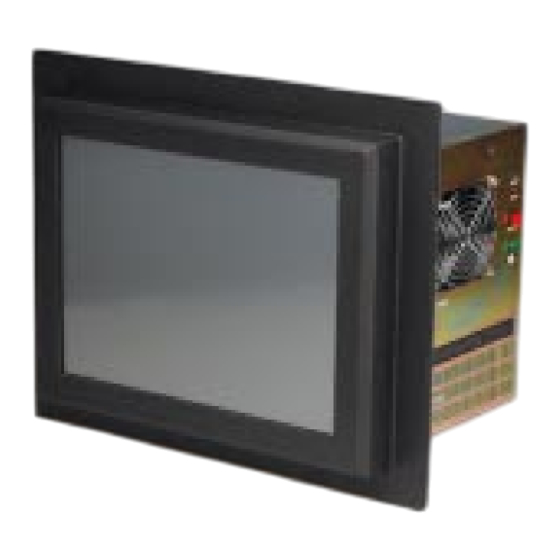
- Page 1 TRANSDUCTION USER’S MANUAL Version 1.0 05/21/09 TR-6001-PM NEMA 4 Panel Mount PC TR-6001-RM NEMA 4 Rack Mount PC with Intel Core 2 Quad and Core 2 Duo and Celeron D Processor 5155-23 Spectrum Way, Mississauga, ON, Canada L4W 5A1 TEL: 1-800-268-0427, 905-625-1907...
-
Page 2: Table Of Contents
Exit Selecting ..............88 Chapter 5 - Appendix I/O Port Address Map ........... 90 Interrupt Request Lines (IRQ) ........91 POST Beep ..............92 TR-6001 Mechanical Drawings ........93-99 TR-6001 PCI 6S Drawing ..........100 TR-6001 1U USB Filler Drawing ........101... -
Page 3: Important Information
Descrip on of the failure Mark the RMA number clearly on the outside of each box, include a failure report and return the product to: Transduc on 5155 – 23 Spectrum Way Mississauga ON Canada L4W 5A1 A n: RMA Department TR-6001 User Manual... -
Page 4: Recommended Use
• When opera ng the TR-6001 with its AC 125-240V power supply, use a power supply cord that matches the power supply voltage of the AC power outlet being used. The power supply cord you use must have been approved by and comply with the safety standards of your country. - Page 5 Introduction This chapter is designed to give you an overview on the TR-6001 industrial PC. The topics covered are as follows: Contents ............ 2 TR-6001 Specifications ....... 3-4 Driver Installation ........5 Touchscreen ..........6-15 TR-6001 User Manual...
-
Page 6: Contents
Contents Your new TR-6001 box* should contain the following: • TR-6001 PC/LCD • Power Cord • User’s Manual • CD-ROM with drivers TR-6001 Panel/Rack Mount PC User’s Manual Driver CD *Remember to save your original box and packing material to transport or ship the monitor. -
Page 7: Tr-6001 Specifications
TR-6001 Specifica ons Model TR-6001 NEMA 4 Panel Mount and Rack Mount Industrial PC with TFT LCD Touch Screen Processor Intel Socket 775 for Core 2 Quad, Core 2 Duo or Celeron D with 800/1066/1333MHz FSB Display 15” TFT LCD display... - Page 8 Addi onal Op ons 9U rack mount version Rear access Floppy/CD op on Wall moun ng bracket High speed flash SATA SSD 16 ~ 128GB IDE RAID 1 op on BNC IRIG A/B me sync op on TR-6001 User Manual...
-
Page 9: Driver Installation
Install Hi-Speed USB 2.0 Driver The selec on helps you to install the driver of the on-board USB 2.0 interface. Browse the CD The selec on helps you to find the drivers in this CD directly. TR-6001 User`s Manual... -
Page 10: Touchscreen
Touchscreen USB Controller Driver Installa on All Windows drivers are included on the Transduc on TR-6001 8-wire Touchscreen Drivers CD along with Troubleshoo ng. NOTE: For Win XP and 2000 you MUST logon with administrator’s password. TouchKit so ware on the driver CD has the required drivers and the u lity for toggling between le and right mouse bu ons and configura on... - Page 11 A er calibra on, the new record will overwrite the old one. 2. SETTING: Sound, Mouse Mode and Double Click Adjustment Sound TR-6001 User Manual...
- Page 12 Mouse Bu on Click it to show/hide Touch Tray on the right bo om corner of the desktop. Users can choose show or hide Touch Tray from the mouse icon in the taskbar. TR-6001 User Manual...
- Page 13 When the Op on bu on is pressed, a se ng property sheet will pop up. Support Constant Touch and Support Auto Right Bu on check boxes are shown in the property sheet to enable/disable constant touch and Auto right bu on support. TR-6001 User Manual...
- Page 14 Cursor visibility func on allows the cursor to be hidden. Go to Start / Control Panel / Mouse / Pointers / Scheme, and choose TouchKit Hide Cursor. Press [Apply] to make the se ng change, and press [OK] to escape the property page. Double Click Adjustment TR-6001 User Manual...
- Page 15 If you set the Edge to <Smaller>, TouchKit will reduce the horizontal posi on of the top edge. If you set the Edge to <Larger>, TouchKit will extend the horizontal posi on of the top edge. TR-6001 User Manual...
- Page 16 If you set the Offset Y Axis to <Smaller>, cursor will be moved one pixel above the Y Axis. If you set the Offset Y Axis to < Larger>, cursor will be moved one pixel below the Y Axis. TR-6001 User Manual...
- Page 17 The bu on [Mapping] is used to find the mapping rela onships between the monitors and touch panel controllers. Press [Mapping] and the so ware will guide you to touch the corresponding monitor to obtain the mapping rela onship. TR-6001 User Manual...
- Page 18 Le : 0, Right: 0, Top: 0 and Bo om: 0. 5. ABOUT: General informa on about TouchKit. Uninstalling TouchKit To uninstall, use the TouchKit/Uninstall from the Programs menu on the Start bu on. TR-6001 User Manual...
- Page 19 Declara on of the Manufacturer We hereby cer fy that the TR-6001 is in compliance with TRANSDUCTION 5155 Spectrum Way Bldg 23 Mississauga, ON L4W 5A1 Canada 905-625-1907 www.transduc on.com TR-6001 User Manual...
- Page 20 TR-980 SBC Introduction This chapter provides information on TR-6001 single board computer, TR-980. The topics covered are as follows: Features ............. 17 Specifications ..........18-20 TR-6001 User Manual...
-
Page 21: Features
IRDA, 1x PIDE, 1x LPT, 1x FLOPPY. High-Definition Audio Codec support Line-out, Line-in and Microphone, CD-IN and SPDIF. PICMG 1.0 Standard form factor support PCI and ISA interface. Multiple display technology: Support CRT, Dual channel 24-bits LVDS LCD display and DVI interface Display. TR-6001 User Manual... -
Page 22: Specifications
COM1~COM2 are pin-header for internal connections. One Floppy connector supports up to floppy drives. One Parallel port supports SPP/ECP/EPP mode. One IrDA port. One Mini-DIN connector on I/O bracket to support PS2 Keyboard and mouse. TR-6001 User Manual... - Page 23 Temperature Monitor: One sensor close to CPU socket for CPU temperature detection. One sensor close to 83627HF chip for board temperature detection. One CPU FAN for CPU cooler, one SYS FAN for chassis FAN. All FAN speeds are monitored. TR-6001 User Manual...
- Page 24 One Buzzer (9mm) on-board for beep message. Operating Temperature: 0~60°C Operation Range. -40C to 70C storage. Relative Humility: 5~95%, non-condensing. Dimensions: 13.3” (L) x 4.8” (W); or 338mm (L) x 124mm (W). PICMG 1.0 Standard Form Factor. TR-6001 User Manual...
-
Page 25: Chapter 3 - Installations
Installations This chapter provides information on how to use the jumpers and connectors on the TR-980. The topics covered are as follows: Jumpers on the TR-980 ......22-25 Connectors on the TR-980 ......26-41 TR-6001 User Manual... - Page 26 Jumper Locations on the TR-980 TR-6001 User Manual...
- Page 27 (3) Short the pin2 and pin3 for three seconds. (4) Put Jumper cap back to pin1 & 2. (5) Turn on your computer. (6) Hold Down <Delete> during boot up and enter BIOS setup to enter your preferences. Clear CMOS Normal Operation Content (default) TR-6001 User Manual...
- Page 28 1066Mhz FSB JP3: Pin 1-2 short JP4: Pin 1-2 short JP4 JP3 JP2 JP2: Pin 1-2 short 1333Mhz FSB JP3: Pin 1-2 short JP4 JP3 JP2 AT_MODE: Power Supply Mode Selection AT mode ATX mode (default) AT_MODE AT_MODE TR-6001 User Manual...
- Page 29 LCDPWR can be used to select the Panel LCD supple power: +3.3V or +5V.The default setting is on +3.3V.User need to check the LCD panel spec and adjust this jumper to make Panel work in specified power rail. This Jumper serves LVDS LCD connector. +3.3V(default) TR-6001 User Manual...
- Page 30 Connector Locations on the TR-980 TR-6001 User Manual...
- Page 31 DIO_1 DIO_5 DIO_2 DIO_6 DIO_3 DIO_7 USB12, 34, 56 Connectors The following table shows the pin outs of the USB12, USB34, USB56 connectors. Signal Pin # Pin # Signal Name Name N.C. USB- USB+ USB+ USB- N.C. TR-6001 User Manual...
- Page 32 Pin # Signal Name SATATX+ SATATX- SATARX- SATARX+ VGA Connector The pin assignments of VGA CRT connector are as follows: Signal Name Pin # Pin # Signal Name Green Blue N.C. N.C. N.C. DDC_DATA HSYNC VSYNC DDC_CLK TR-6001 User Manual...
- Page 33 TX/RX activity. The Orange/Green Dual color LED on the left-hand side indicates the operation mode, i.e. 10Base-T, 100Base-T or 1000Base-T. LNK/ACT STATUS GREEN Link Disconnected FLASH Packets TX/RX SPEED MODE ORANGE 1000 Mbps GREEN 100 Mbps 10 Mbps TR-6001 User Manual...
- Page 34 AUDIO Connector Pin # Signal Name MIC1-IN-L MIC1-IN-R AGND AGND LINEOUT-L LINE-IN-L LINEOUT-R LINE-IN-R CD_IN Connector CD_IN connector is designed for wire the CD_ROM audio signals to the on-board Audio CODEC. Pin # Signal Name CD_Left CD_Right TR-6001 User Manual...
- Page 35 This 2-pin connector acts as the “Power Supply On/Off Switch” on the TR-980 main board. When pressed, the switch will force the Main board to power on. When pressed again, it will force the main board to power off. PWRBTN Signal Name Pin # 5VSB PWRBTN TR-6001 User Manual...
- Page 36 Orientation is not required when making a connection to this header. RESET1 Signal Name Pin # SYS_RST Ground KEYLOCK Switch The keylock switch, when closed, will disable the keyboard function. RESET Signal Name Pin # KEYLOCK TR-6001 User Manual...
- Page 37 This is a 3-pin header for the CPU fan. Pin # Signal Name Ground +12V CPUPWM IRDA Connector This connector is used for an IrDA connector for wireless communication. IrDA Pin # Signal Name IR-RX Ground IR-TX TR-6001 User Manual...
- Page 38 RXD, Receive data RX+ (422) TXD, Transmit data RX- (422) DTR, Data terminal ready GND, ground N.C. DSR, Data set ready N.C. RTS, Request to send N.C. CTS, Clear to send N.C. +5V,Ring-IN or +12V N.C. N.C. TR-6001 User Manual...
- Page 39 LAN1_LED Connector The 4-pins LAN1_LED connector designed for LAN1 port is for applications need to display LAN1 port status on front panel or the places administrators are easy to access. Pin # Signal Name 1_ACTLED 1_PULUP 1_LINK1000 1_LINK100 TR-6001 User Manual...
- Page 40 Signal Name SPDIFO SPDIFI ATX_12V Connector The ATX_12V power connector mainly supplies power to the CPU. Caution! If the ATX_12V power connector is not connected, the system will not start. Pin # Signal Name +12V ATX_12V +12V TR-6001 User Manual...
- Page 41 Ground Motor enable 1 Ground Direction Ground Step Ground Write data Ground Write gate Ground Track 00 Ground Write protect Ground Read data Ground Side 1 select Ground Diskette change WOL Connector Pin # Signal Name 5VSB TR-6001 User Manual...
- Page 42 PD2, parallel data 2 Select PD3, parallel data 3 Ground PD4, parallel data 4 Ground PD5, parallel data 5 Ground PD6, parallel data 6 Ground PD7, parallel data 7 Ground ACK, acknowledge Ground Busy Ground Paper empty Ground Select TR-6001 User Manual...
- Page 43 DVI Connector Signal Signal Name Name TCLK+ TDC1+ TCLK- TDC1- TDC0+ TDC2+ TDC0- TDC2- CLOCK DATA DVI_PLUG BACKLITE Connector Pin # Signal Name +12V Brightness ON/OFF TR-6001 User Manual...
- Page 44 +12V LCDVDD 5V/3.3V LCDVDD 5V/3.3V BRIGHTNES BCKLITE_ON LVDS_GND LVDS_GND CHA_TX0+ CHB_TX0+ CHA_TX0- CHB_TX0- LVDS_GND LVDS_GND CHA_TX1+ CHB_TX1+ CHA_TX1- CHB_TX1- LVDS_GND LVDS_GND CHA_TX2+ CHB_TX2+ CHA_TX2- CHB_TX2- LVDS_GND LVDS_GND CHA_TXC+ CHB_TXC+ CHA_TXC- CHB_TXC- LVDS_GND LVDS_GND CHA_TX3+ CHB_TX3+ CHA_TX3- CHB_TX3- TR-6001 User Manual...
- Page 45 Pin # Signal Name PWOK 5VSB PS_ON- When using ATX power supply soft-on/off function, please make sure remove AT_MODE jumper. The setting is illustrated as below: BACKPLANE CABLE TR-980 TR-6001 User Manual...
- Page 46 Power Management Setup ......72-77 PnP/PCI Configuration ........78-82 PC Health Status ..........83-84 Load Fail-Safe Defaults ........85 Load Optimized Defaults ....... 85 Set Supervisor/User Password ..... 86-87 Save & Exit Setup .......... 88 Exit Without Saving ........88 TR-6001 User Manual...
-
Page 47: Bios Introduction
And the firmware chip will store the setup utility on the board. However, if you want to enter the setup after the POST, you can press Ctrl + Alt + Del simultaneously or turn off the power then back TR-6001 User Manual... -
Page 48: Main Menu
Use this menu for basic system configuration. Advanced BIOS Features Use this menu to set the Advanced Features available on your system. Advance Chipset Features Use this menu to change the values in the chipset registers and optimize your system's performance. TR-6001 User Manual... - Page 49 Set Supervisor/ User Password Use this menu to set User and Supervisor Passwords. Save & Exit Setup Save CMOS value changes to CMOS and exit setup. Exit Without Saving Abandon all CMOS value changes and exit setup. TR-6001 User Manual...
-
Page 50: Standard Cmos Setup
Drive B [None] Video [EGA/VGA] Halt On [All , But Disk/Key] Base Memory 639K Extend Memory 513024K Total Memory 514048K Move Enter: Select +/-/PU/PD: Value F10:Save Esc: Exit F1:General Help F5:Previous Value F6:Fail-Safe Defaults F7:Optimized Default (Figure 2) TR-6001 User Manual... - Page 51 All, but Disk/Key Base Memory Displays the amount of conventional memory detected during boot up Extended Memory Displays the amount of extended memory detected during boot up Total Memory Displays the total memory available in the system TR-6001 User Manual...
- Page 52 Access Mode [Auto] To auto-detect the HDD’s Capacity 0 MB size, head…on this channel Cylinder Head Precomp Landing Zone Sector Move Enter: Select +/-/PU/PD: Value F10:Save Esc: Exit F1:General Help F5:Previous Value F6:Fail-Safe Defaults F7:Optimized Default (Figure 3) TR-6001 User Manual...
- Page 53 Cylinder Head Move Enter: Accept Esc: Abort Precomp Landing Zone Sector Move Enter: Select +/-/PU/PD: Value F10:Save Esc: Exit F1:General Help F5:Previous Value F6:Fail-Safe Defaults F7:Optimized Default (Figure 4) Extended IDE Drive The choice: None, Auto (default) TR-6001 User Manual...
- Page 54 Min = 0 **** Warning: Setting a value Max = 65535 of 65535 means no hard disk Landing zone Min = 0 **** Max = 65535 Sector Min = 0 Number of sectors per track Max = 255 TR-6001 User Manual...
- Page 55 The system boot will not be halted for a disk error; it will stop for all other errors. All, But Disk/Key The system boot will not be halted for a key- board or disk error; it will stop for all others. (default) TR-6001 User Manual...
-
Page 56: Advanced Bios Features
MPS Version Control For OS [1.4] OS Select For DRAM > 64MB [Non-OS2] Report No FDD For WIN 95 [No] Move Enter: Select +/-/PU/PD: Value F10:Save Esc: Exit F1:General Help F5:Previous Value F6:Fail-Safe Defaults F7:Optimized Default (Figure 5) TR-6001 User Manual... - Page 57 F1:General Help F5:Previous Value F6:Fail-Safe Defaults F7:Optimized Default (Figure 6) PPM Mode The choice: Native Mode (default), SMM Mode. Limit CPUID Max Val The choice: Enabled, Disabled (default). C1E Function The choice: Auto (default), Disabled. Execute Disabled Bit The choice: Enabled, Disabled (default). TR-6001 User Manual...
- Page 58 F1:General Help F5:Previous Value F6:Fail-Safe Defaults F7:Optimized Default (Figure 7) Bootable Add-in Cards This is for setting the priority of the hard disk boot order when the “Hard Disk” option is selected in the “[First/Second/Third] Boot Device “menu item. TR-6001 User Manual...
-
Page 59: Virus Warning
The BIOS attempts to load the operating system from the devices in the sequence selected in these items. The Choice: Floppy, LS120, Hard-Disk, ZIP100, CDROM, Disabled, USB-FDD, USB-ZIP, USB-CDROM, Legacy LAN. Item Default First Boot Device Hard-Disk Second Boot Device CDROM Third Boot Device LS120 TR-6001 User Manual... - Page 60 Keystrokes repeat at a rate determined by the keyboard controller. When enabled, the typematic rate and typematic delay can be selected. The choice: Enabled, Disabled (default). If Typematic Rate Setting is [Enabled], can choice Rate and Delay: TR-6001 User Manual...
- Page 61 Sets the delay time after the key is held down before it begins to repeat the keystroke. The choice: 250 (default), 500, 750, and 1000. Typematic Delay (Msec) ….. [ ….. [ ] ….. [ ] 1000 ….. [ ] : Move Enter: Accept ESC: Abort TR-6001 User Manual...
-
Page 62: Security Option
OS Select For DRAM > 64MB Select OS2 only if you are running OS/2 operating system with greater than 64MB of RAM on the system. The choice: Non-OS2 (default), OS2. Report No FDD For WIN 95 The choice: No (default), Yes. TR-6001 User Manual... -
Page 63: Advanced Chipset Features
DVMT Mode [DVMT] DVMT / FIXED Memory Size [128MB] Boot Display Lan1 Chip Control [Enabled] Lan2 Chip Control [Enabled] Move Enter: Select +/-/PU/PD: Value F10:Save Esc: Exit F1:General Help F5:Previous Value F6:Fail-Safe Defaults F7:Optimized Default (Figure 8) TR-6001 User Manual... - Page 64 Leave this on the default setting. The choice: Auto (default), 2, 3,4,5,6. Precharge dealy (tRAS) The choice: Auto (default), 4,5,6,7,8,9,10,11,12,13,14,15. System Memory Frequency The choice: Auto (default), 533MHz, 667MHz. System BIOS Cacheable The choice: Enabled (default), Disabled. TR-6001 User Manual...
-
Page 65: Memory Hole At 15M-16M
PCI-E Compliancy Mode The choice: v1.0a (default), v1.0. On-Chip Frame Buffer Size User can select frame buffer size. The choice: 1MB, 8MB (default). DVMT Mode This field shows the current DVMT mode. The choice: FIXED, DVMT (default), BOTH. TR-6001 User Manual... - Page 66 The choice: Auto (default), CRT, TV, EFP, LFP, CRT+LFP, ERP+LFP. Panel Number These fields allow you to select the LCD Panel type. The choice: 1~16. 3(default) Lan1 Chip Control The choice: Enabled (default), Disabled. Lan2 Chip Control The choice: Enabled (default), Disabled. TR-6001 User Manual...
-
Page 67: Integrated Peripherals
IDE Secondary Slave UDMA [Auto] lock read/writes SATA Mode [IDE] per sector the drive LEGACY Mode Support [Disabled] can support Move Enter: Select +/-/PU/PD: Value F10:Save Esc: Exit F1:General Help F5:Previous Value F6:Fail-Safe Defaults F7:Optimized Default TR-6001 Use Manual... - Page 68 The BIOS will automatically set the system according to your hard disk drive’s timing (default). Mode 0-4 You can select a mode that matches your hard disk drive’s timing. IDE Primary/Secondary, Master/ Slave UDMA The choice: Disabled, Auto (default). TR-6001 User Manual...
- Page 69 F1:General Help F5:Previous Value F6:Fail-Safe Defaults F7:Optimized Default Onboard FDC Controller The choice: Enabled (default), Disabled. Onboard Serial Port 1 Select an address and corresponding interrupt for the first serial ports. The choice: Disable, 3F8/IRQ4 (default), 2F8/IRQ3, 3E8/IRQ4, 2E8/IRQ3, Auto. TR-6001 User Manual...
- Page 70 F1:General Help F5:Previous Value F6:Fail-Safe Defaults F7:Optimized Default RxD, TxD Active The choice: UART Mode Select Hi, Hi ……[ ] Hi, Lo ……[ ] Lo, Hi …..[ ] Lo, Lo …..[ ] : Move Enter: Accept ESC: Abort TR-6001 User Manual...
- Page 71 Onboard Parallel Port [378/IRQ7] Parallel Port Mode [SPP] x EPP Mode Select EPP1.7 x ECP Mode Use DMA PWRON After PWR-Fail [Off] Move Enter: Select +/-/PU/PD: Value F10:Save Esc: Exit F1:General Help F5:Previous Value F6:Fail-Safe Defaults F7:Optimized Default TR-6001 User Manual...
- Page 72 [Half] Onboard Parallel Port [378/IRQ7] Parallel Port Mode [ECP] x EPP Mode Select ECP Mode Use DMA PWRON After PWR-Fail [Off] Move Enter: Select +/-/PU/PD: Value F10:Save Esc: Exit F1:General Help F5:Previous Value F6:Fail-Safe Defaults F7:Optimized Default TR-6001 User Manual...
- Page 73 ECP, you must use this setting to assign a DMA channel for use by the port. The choice: DMA1, DMA3 (default). PWRON After PWR-Fail When power fails, you can select power ON or Off or Former status. The choice: Off (default), On, Former-Sts. TR-6001 User Manual...
- Page 74 If the BIOS has high speed USB support built in, the support will be automatically turn on when high speed device were attached. The choice: Enabled (default), Disabled. USB Operation Mode The choice: Full/Low Speed, High Speed (default). USB Keyboard Function The choice: Enabled (default), Disabled. TR-6001 User Manual...
- Page 75 USB Mouse Function The choice: Enabled (default), Disabled. USB Storage Function The choice: Enabled (default), Disabled. TR-6001 User Manual...
-
Page 76: Power Management Setup
Primary IDE 1 [Disabled] Secondary IDE 0 [Disabled] Secondary IDE 1 [Disabled] FDD , COM , LPT Port [Disabled] PCI PIRQ[A-D]# [Disabled] Move Enter: Select +/-/PU/PD: Value F10:Save Esc: Exit F1:General Help F5:Previous Value F6:Fail-Safe Defaults F7:Optimized Default TR-6001 User Manual... -
Page 77: Power Management
CPUs. Inactivity period is 1 minute in each mode. User Define Set each mode individually. Select time-out periods in the section for each mode, below. Min Saving Minimum power savings. Inactivity period is 1 hour in each mode (except the hard drive). TR-6001 User Manual... -
Page 78: Video Off Method
This field specifies the length of time of system inactivity while in full power on state before the computer enters suspend mode and motivates the enable 'Wake up Events in Doze & Standby' / 'PM Events'. The choice: 1Min, 2Min, 4Min, 8Min, 12Min, 20Min, 30Min, 40Min,1Hour, Disable (default). TR-6001 User Manual... - Page 79 This field, when enabled, allows you to use a USB keyboard to wake up a system that is in the S3 (STR - Suspend To RAM) state. This can be configured only if the ‘ACPI Suspend Type’ field is set to ‘S3 (STR)’. The choice: Enabled, Disabled (default). TR-6001 User Manual...
- Page 80 Key in a DEC number: wwww : Move Enter: Accept ESC:Abort Primary/ Secondary IDE 0/1 When Enabled, the system will resume from suspend mode if Primary IDE 0 (1) or Secondary IDE 0 (1) is active. The choice: Enabled, Disabled (default). TR-6001 User Manual...
- Page 81 When Enabled, the system will resume from suspend mode if FDD, COM port, or LPT port is active. The choice: Enabled, Disabled (default). PCI PIRQ [A-D] # When Enabled, the system will resume from suspend mode if interrupt occurs. The choice: Enabled, Disabled (default). TR-6001 User Manual...
-
Page 82: Pnp/Pci Configuration
Move Enter: Select +/-/PU/PD: Value F10:Save Esc: Exit F1:General Help F5:Previous Value F6:Fail-Safe Defaults F7:Optimized Default Init Display First This item allows you to choose which one to activate first, PCI Slot or onchip VGA. The choice: PCI Slot (default), Onboard, PCIEx. TR-6001 User Manual... - Page 83 INT Pin 6 Assignment [Auto] INT Pin 7 Assignment [Auto] INT Pin 8 Assignment [Auto] **PCI Express relative items** Maximum Payload Size [128] Move Enter: Select +/-/PU/PD: Value F10:Save Esc: Exit F1:General Help F5:Previous Value F6:Fail-Safe Defaults F7:Optimized Default TR-6001 User Manual...
- Page 84 Move Enter: Select +/-/PU/PD: Value F10:Save Esc: Exit F1:General Help F5:Previous Value F6:Fail-Safe Defaults F7:Optimized Default IRQ-3,4,5,7,9,10,11,12,14,15 assigned to IRQ-3 assigned to PCI /ISA PnP ….. [ s ] Legacy ISA ….. [ : Move Enter: Accept ESC:Abort The choice: PCI/ISA PnP, Legacy ISA. TR-6001 User Manual...
- Page 85 F5:Previous Value F6:Fail-Safe Defaults F7:Optimized Default DMA-0 , 1, 3, 5, 6, 7 assigned to IRQ-3 assigned to PCI /ISA PnP ….. [ s ] Legacy ISA ….. [ : Move Enter: Accept ESC:Abort The choice: PCI/ISA PnP, Legacy ISA. TR-6001 User Manual...
-
Page 86: Int Pin 1/2/3/4/5/6/7/8 Assignment
This BIOS feature determines if your graphics card should allow VGA palette snooping by a fixed function display card. The choice: Enabled, Disabled (default). INT Pin 1/2/3/4/5/6/7/8 Assignment The choice: Auto (default),3,4,5,7,9,10,11,12,14,15. Maximum Payload Size The choice: 128 (default). TR-6001 User Manual... -
Page 87: Pc Health Status
The choice: Disabled (default), 50 C/122 F, 53 C/127 F, 56 C/133 F, 60 C/140 F, 63 C/145 F, 66 C/151 F, and 70 C/158 F. Current System Temp Show System Temperature. Current CPU Temp Shows Board Temperature. TR-6001 User Manual... -
Page 88: Shutdown Temperature
CPU Fan CHASSIS Fan Speed Shows CHASSIS speed. POWER Fan Speed Shows POWER speed. Shutdown Temperature Select the CPU over-heated shutdown temperature. The choice: Disabled (default), 60 C/140 F, 65 C/149 F, 70 C/158 F, 75 C/167 F. TR-6001 User Manual... -
Page 89: Frequency/Voltage Control
Load Optimized Defaults (Y/N)? N Save & Exit Setup ►PC Health Status Exit Without Saving Esc :Quit Select Item F10:Save & Exit Setup Pressing ‘Y’ loads the default values that are factory settings for optimal performance system operations. TR-6001 User Manual... -
Page 90: Set Supervisor/User Password
►Advance Chipset Features Load Optimized Default ►Integrated Peripherals Set Supervisor Password ►Power Management Set User Password ►PnP/PCI Configuration Save & Exit Setup ►PC Health Status Enter Password: Exit Without Saving Esc :Quit Select Item F10:Save & Exit Setup TR-6001 User Manual... - Page 91 ENTER PASSWORD: Type the password, up to eight characters in length, and press <Enter>. The password typed now will clear any previously entered password from CMOS memory. You will be asked to confirm the password. Type the password again and press <Enter>. You may also press <Esc>...
-
Page 92: Supervisor/User Password Settings
Exit Without Saving Esc :Quit Select Item F10:Save & Exit Setup This allows you to exit Setup without storing in CMOS any change. The previous selections remain in effect. This exits the Setup utility and restarts your computer. TR-6001 User Manual... - Page 93 The topics covered are as follows: I/O Port Address Map .......... 90 Interrupt Request Lines (IRQ) ....... 91 Post Beep .............. 92 TR-6001 Mechanical Drawings ......93-99 TR-6001 PCI 6S Drawing ........100 TR-6001 1U USB Filler Drawing ......101 TR-6001 User Manual...
-
Page 94: I/O Port Address Map
Parallel Port #1(LPT1) 360 - 36F Network Ports 3B0 - 3BF Monochrome & Printer adapter 3C0 - 3CF EGA adapter 3D0 - 3DF CGA adapter 3F0h - 3F7h Floppy Disk Controller 3F8h - 3FFh Serial Port #1(COM1) TR-6001 User Manual... -
Page 95: Interrupt Request Lines (Irq)
Serial Port #1 IRQ5 Reserved IRQ6 Floppy Disk Controller IRQ7 Parallel Port #1 IRQ8 Real Time Clock IRQ9 Software Redirected to Int0Ah IRQ10 Reserved IRQ11 Reserved IRQ12 PS/2 Mouse IRQ13 80287 IRQ14 Primary IDE IRQ15 Secondary IDE TR-6001 User Manual... -
Page 96: Post Beep
This beep code consists of a single long beep followed by two short beeps. The other code indicates that your DRAM error has occurred. This beep code consists of a single long beep repeatedly. TR-6001 User Manual...
Need help?
Do you have a question about the TR-6001 and is the answer not in the manual?
Questions and answers