Table of Contents

Related Manuals for Waterous AQUIS ULTRAFLOW 500

Summary of Contents for Waterous AQUIS ULTRAFLOW 500
- Page 1 Form Number: F-3041 Issue Date: Jul 17, 2024 AQUIS™ ULTRAFLOW 500 Controls—Tellurus Control Panel Installation and Operation Waterous Company • 125 Hardman Avenue South • South Saint Paul, MN 55075 • (651) 450-5000 www.waterousco.com...
-
Page 3: Table Of Contents
Table of Contents Safety Safety Precautions Introduction Using this Document Viewing the Document Electronically Printing the Document Additional Documentation Overview Aquis UltraFlow Industrial Foam Proportioner System Control Panel and Components 15-Inch Tellurus Control Panel 8-Inch Tellurus Control Panel WiFi and GPS Antenna Tellurus HMI Cable Tellurus CAN Cable 2.0 Meter CAN Cable... -
Page 4: Safety
• Read and understand all the notices and safety precautions. operating or overhauling the equipment. • Do not operate the equipment when safety guards are removed. • Contact Waterous when you have questions about operating, maintaining, or • Do not modify the equipment. overhauling the equipment. -
Page 5: Introduction
Operation Maintenance Using this Document Use this document to install and operate your Waterous equipment. Understand the following conditions before continuing with the document: Use the guidelines below when viewing this document. • The instructions may refer to options or equipment that you may not have Viewing the Document Electronically purchased with your system. -
Page 6: Aquis Ultraflow Industrial Foam Proportioner System
Safety Introduction Overview Installation Operation Maintenance Aquis UltraFlow Industrial Foam Proportioner System Note: Make sure that the installer-supplied UltraFlow plumbing cannot trap fluid and allows fluid to be drained from the system when required. - Page 7 Safety Introduction Overview Installation Operation Maintenance Aquis UltraFlow Industrial Foam Proportioner System The Aquis UltraFlow industrial foam proportioner system supplies concentrate into a solution-capable discharge line. A Tellurus™ control panel, or human machine interface (HMI), shows system activity and provides control of the system using a CANbus protocol. Foam concentrate is sourced from an on-board supply tank or an auxiliary source.
- Page 8 Safety Introduction Overview Installation Operation Maintenance Aquis UltraFlow Industrial Foam Proportioner System Subsystem Subsystem Description Description Concentrate pump These components support, control, and power the concentrate pump. The components in this subsystem include: • Concentrate pump—this circulates the foam concentrate through the system. •...
- Page 9 Safety Introduction Overview Installation Operation Maintenance Aquis UltraFlow Industrial Foam Proportioner System Subsystem Subsystem Description Description Concentrate supply refill line This allows you to fill the on-board tank from an external source. The components in this subsystem include: • Node controller—this connects to the fill valve and flowmeters. •...
-
Page 10: Control Panel And Components
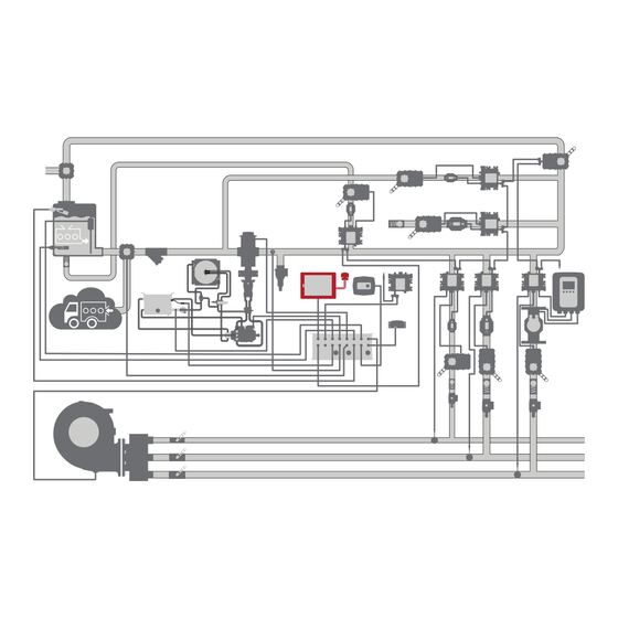
Safety Introduction Overview Installation Operation Maintenance Control Panel and Components A comprehensive application of the UltraFlow system consists of multiple subsystems, including up to 19 DLAs to perform various functions, an on-board and auxiliary concentrate supply, equipment to circulate water and concentrate, and components to monitor and control the system. - Page 11 Safety Introduction Overview Installation Operation Maintenance Control Panel and Components Subsystem Subsystem Description Description Control panel The control panel allows the operator to interface with the control system and displays system information during operation. The components in this subsystem include: •...
-
Page 12: 15-Inch Tellurus Control Panel
Safety Introduction Overview Installation Operation Maintenance 15-Inch Tellurus Control Panel The control panel displays current operations and provides the operator control of the system. - Page 13 Safety Introduction Overview Installation Operation Maintenance 15-Inch Tellurus Control Panel Feature Feature Description Description Reset button This indicates system status and allows the operator to reset the control panel. Touchscreen This displays operations and system controls. Mounting knob These secure the control panel to the apparatus. Mounting bracket These secure the control panel to the apparatus.
-
Page 14: 8-Inch Tellurus Control Panel
Safety Introduction Overview Installation Operation Maintenance 8-Inch Tellurus Control Panel The control panel displays current operations and provides the operator control of the system. - Page 15 Safety Introduction Overview Installation Operation Maintenance 8-Inch Tellurus Control Panel Feature Feature Description Description Reset button This indicates system status and allows the operator to reset the control panel. Touchscreen This displays operations and system controls. Mounting knobs These secure the control panel to the apparatus. Mounting brackets These secure the control panel to the apparatus.
-
Page 16: Wifi And Gps Antenna
Safety Introduction Overview Installation Operation Maintenance WiFi and GPS Antenna The antenna receives WiFi and GPS signals. - Page 17 Safety Introduction Overview Installation Operation Maintenance WiFi and GPS Antenna Feature Feature Description Description Antenna This receives the WiFi and GPS signals. Nut cover This secures the antenna to the apparatus. GPS connector This connects the GPS connector to the control panel. WiFi connector This connects the WiFi connector to the control panel.
-
Page 18: Tellurus Hmi Cable
Safety Introduction Overview Installation Operation Maintenance Tellurus HMI Cable This cable connects the control panel to the control box and system power. The power connector, associated connector components, and wiring are provided by the installer. Use the table to determine pin location. Feature Feature Description... -
Page 19: Tellurus Can Cable
Safety Introduction Overview Installation Operation Maintenance Tellurus CAN Cable 11.81 in 300 mm Feature Feature Description Description M12 connector This connects to the Tellurus HMI CANbus connector on the control box or a CAN cable connected to the control box. Cable This is a violet cable jacket. -
Page 20: 2.0 Meter Can Cable
Safety Introduction Overview Installation Operation Maintenance 2.0 Meter CAN Cable The CAN cable communicates data between the CAN connections. It is typically violet. The CAN cable is not interchangeable with the sensor cable. You can connect 2 or more cables together to achieve a desired length. 6.56 ft Feature Feature... -
Page 21: 0.5 Meter Can Cable
Safety Introduction Overview Installation Operation Maintenance 0.5 Meter CAN Cable The CAN cable communicates data between the CAN connections. It is typically violet. The CAN cable is not interchangeable with the sensor cable. You can connect 2 or more cables together to achieve a desired length. 19.68 in 500 mm Feature... -
Page 22: Installation Overview
This equipment is intended to be installed by a person or persons with the basic This equipment is intended to operate as designed. Do not remove, modify, or knowledge of installing similar equipment. Contact Waterous with questions change the components in the system. Doing so will void the warranty. Contact about installing the equipment. -
Page 23: Determining Panel And Plate Locations
Safety Introduction Overview Installation Operation Maintenance Determining Panel and Plate Locations Determining Cable and Wire Routing Use the following guidelines to determine a location to mount the control panel Use the Wiring Best Practices document, available at www.waterousco.com, as and instruction plate: a guide to select and route wiring for your application. -
Page 24: Control Panel Cables And Connections
Safety Introduction Overview Installation Operation Maintenance Control Panel Cables and Connections... - Page 25 Safety Introduction Overview Installation Operation Maintenance Control Panel Cables and Connections Feature Feature Description Description Control panel This displays system operation and provides the operator control of the system. Antenna This transmits and/or receives WiFi and GPS signals. Tellurus HMI cable This connects the control panel to power and to the Tellurus CAN cable.
-
Page 26: Connecting The Control Panel
Safety Introduction Overview Installation Operation Maintenance Connecting the Control Panel Use the illustration and instructions to connect the control panel to the control box. 1 Connect the Tellurus HMI cable to the control panel connector. 2 Connect the Tellurus HMI cable to the Tellurus CAN cable 3 Connect the Tellurus CAN cable to the control box—Tellurus HMI CANbus connector. - Page 27 Safety Introduction Overview Installation Operation Maintenance Connecting the Keyboard and USB Drive Use the illustrations and instructions to connect an external keyboard and USB drive to the control panel. The USB drive can be used to download and save the current configuration file, upload a new configuration, or restore a previous configuration.
-
Page 28: Operation
Safety Introduction Overview Installation Operation Maintenance Configuring and Operating the System The UltraFlow system is composed of elements that are configured to your specific application, including DLAs, flowmeters, valves, switches, sensors, and more. The system is configured using the UltraFlow configuration wizard, a software assistant that guides you through the configuration steps on the control panel touchscreen. -
Page 29: Maintenance
Safety Introduction Overview Installation Operation Maintenance Maintenance Schedule No scheduled maintenance is required for the control system. However, it is recommended that you periodically inspect the system to reveal excess debris buildup, worn components, or any developing leaks. Consider environmental conditions, hours of operation, and other factors specific to your application to develop a suitable inspection schedule. - Page 30 Waterous Company 125 Hardman Avenue South South Saint Paul, MN 55075 (651) 450-5000 www.waterousco.com...
Need help?
Do you have a question about the AQUIS ULTRAFLOW 500 and is the answer not in the manual?
Questions and answers