
Subscribe to Our Youtube Channel
Related Manuals for Littelfuse SE-701

Summary of Contents for Littelfuse SE-701
- Page 1 Tel: +1-800-832-3873 E-mail: relays@littelfuse.com www.littelfuse.com/SE-701 SE-701 MANUAL GROUND-FAULT MONITOR Revision 11-E-032924 Copyright © 2024 by Littelfuse All rights reserved. Document Number: PM-1040-EN...
- Page 2 SE-701 Ground-Fault Monitor Rev.11-E-032924 Page i This page intentionally left blank.
- Page 3 ONTENTS IST OF IGURES ECTION IGURE Introduction ............1 SE-701 Outline and Mounting Details ....5 1.1 General ..............1 Typical Connection Diagrams ......6 1.2 Current-Sensor Selection ........1 Typical Three-Phase-Starter Connection .... 6 Operation ............. 2 EFCT-1 Outline and Mounting Details ....8 2.1 Configuration-Switch Settings ......
- Page 4 SE-701 Ground-Fault Monitor Rev.11-E-032924 Page iii This page intentionally left blank.
- Page 5 1% increments from 1 to 99% of the CT rating. 1.2 C URRENT- ENSOR ELECTION An SE-701 has inputs for 1-, 5-A, and 50- mA-secondary CTs. Choose a CT that provides the required ground-fault-trip range. For ground-fault detection, the ground-fault trip level must be substantially below the prospective ground-fault current.
- Page 6 CT- In the fail-safe mode, non-volatile memory retains primary rating. the trip status of the SE-701. If tripped, and the supply voltage is cycled, the SE-701 will remain tripped, with In tripping systems, a ground-fault trip level of 10 to...
- Page 7 SE-701 Ground-Fault Monitor Rev.11-D-032824 Page 3 2.2.4 T The TEST button is used to test the ground- fault circuit, the indication, and the output relay. When the TEST button is pressed for one second, a test signal is applied to the ground-fault-detection circuit, the circuit will trip, the TRIP LED will light, and the output relay will operate.
- Page 8 OTE: wiring must conform to applicable local electrical codes. Check all applicable codes prior to installation. An SE-701 can be surface or DIN-rail-mounted. See Fig. 1. Panel mounting requires a PMA-55 or PMA-60 Panel-Mount Adapter. See Figs. 8 and 9.
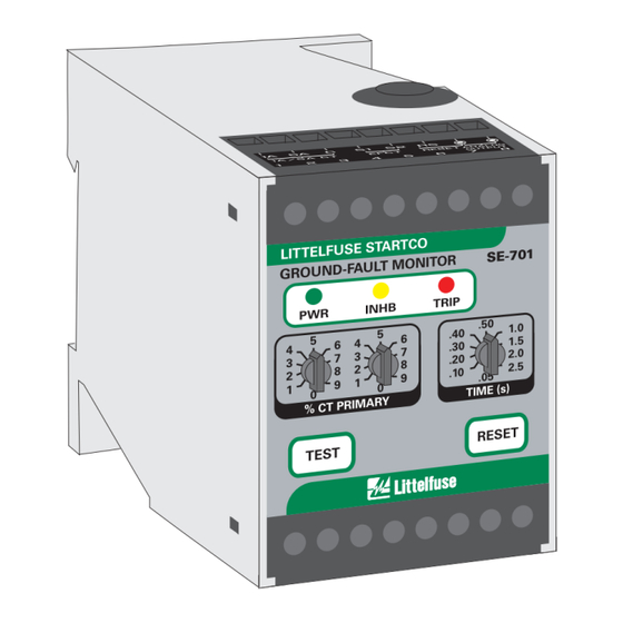
- Page 9 SE-701 Ground-Fault Monitor Rev.11-E-032924 Page 5 FIGURE 1. SE-701 Outline and Mounting Details.
- Page 10 SE-701 Ground-Fault Monitor Rev.11-E-032924 Page 6 FIGURE 2. Typical Connection Diagrams. FIGURE 3. Typical Three-Phase-Starter Connection.
- Page 11 Rev.11-E-032924 Page 7 4. SE-701 C OMPATIBILITY The SE-701 has been enhanced with the addition of The SE-701 was previously available with SE-701-01 non-volatile trip memory for the fail-safe relay 120-Vac and SE-701-02 240-Vac supply-voltage operating mode. Prior to hardware revision 07, a options.
- Page 12 SE-701 Ground-Fault Monitor Rev.11-E-032924 Page 8 FIGURE 4. ELCT5-88 and ELCT30-88 Outline and Mounting Details. FIGURE 5. ELCT5-31 and ELCT30-31 Outline and Mounting Details.
- Page 13 SE-701 Ground-Fault Monitor Rev.11-E-032924 Page 9 FIGURE 6. EFCT-2 Outline and Mounting Details.
- Page 14 SE-701 Ground-Fault Monitor Rev.11-E-032924 Page 10 FIGURE 7. SE-CS30-4, -5, and -8 Current Sensors.
- Page 15 SE-701 Ground-Fault Monitor Rev.11-E-032924 Page 11 FIGURE 8. PMA-55 Panel-Mount Adapter.
- Page 16 SE-701 Ground-Fault Monitor Rev.11-E-032924 Page 12 FIGURE 9. PMA-60 Panel-Mount Adapter.
- Page 17 SE-701 Ground-Fault Monitor Rev.11-E-032924 Page 13 FIGURE 10. PGA-0500 Analog Percent Current Meter.
- Page 18 SE-701 Ground-Fault Monitor Rev.11-E-032924 Page 14 5. TECHNICAL SPECIFICATIONS Input: Algorithms ......DFT or Peak Supply: DFT 3 dB Frequency Resp ... 32 to 86 Hz 0U Option ......5 VA, 120 to 240 Vac, Peak 3 dB Frequency Resp .. 20 to 420 Hz CT .........
- Page 19 SE-701 Ground-Fault Monitor Rev.11-E-032924 Page 15 Terminals ........Wire-clamping, Surge Immunity ....IEC 61000-4-5 24 to 12 AWG Zone B (0.2 to 2.5 mm ± 1 kV differential mode conductors ± 2 kV common mode Dimensions: Surge Withstand ....IEEE C37.90.1:2012 Height ........
- Page 20 SE-701 Ground-Fault Monitor Rev.11-E-032924 Page 16 5SHT-101-E ......Current Sensor, 6. O RDERING NFORMATION 100-A-primary rating, 40 mm (1.6 in.) window 5SHT-151-E ......Current Sensor, 150-A-primary rating, 40 mm (1.6 in.) window 5SHT-500-E ......Current Sensor, 50-A-primary rating, 40 mm (1.6 in.) window 7SHT-301-E ......
- Page 21 Littelfuse will (at Littelfuse’s option) repair, replace, or refund the original purchase price of an SE-701 that is determined by Littelfuse to be defective if it is returned to the factory, freight prepaid, within the warranty period.
- Page 22 SE-400 Ground-Fault-Relay Test Unit. The SE-400 has a programmable output of 0.5 to 9.9 A for a FIGURE 11. Ground-Fault-Test Circuits. duration of 0.1 to 9.9 seconds. Set the test current to 120% of the SE-701 setting. Fig. 11 (b) shows test circuit using an SE-100T Ground-Fault-Relay Tester.
- Page 23 SE-701 Ground-Fault Monitor Rev.11-E-032924 Page 19 TABLE 2. G ROUND- AULT- ECORD ESULTS Retain this record for the authority having jurisdiction.
- Page 24 SE-701 Ground-Fault Monitor Rev.11-E-032924 Page 20 APPENDIX A SE-701 REVISION HISTORY MANUAL MANUAL PRODUCT REVISION RELEASE DATE REVISION (REVISION NUMBER ON PRODUCT LABEL) March 28, 2024 11-E-032924 July 24, 2014 10-C-072414 October 21, 2013 10-B-102113 April 12, 2013 10-A-041213 ANUAL...
Need help?
Do you have a question about the SE-701 and is the answer not in the manual?
Questions and answers