Table of Contents
Advertisement
Quick Links
Advertisement
Table of Contents

Summary of Contents for Green Energy MB51400-300A-HWB
- Page 1 51.2V400AH (300 A BMS) USER MANUAL SOLAR ENERGY STORAGE SYSTEM...
- Page 2 Features ● Using LiFePO4 cote technology, higher safety, 80% DOD charging and discharging under standard conditions, more than 6000 cycles. ● High integrated analog front end, isolated power circuit. Integrated serial port lC, highvoltage accuracy(≤ 20mV), high current accuracy(≤2% @ FS) ●...
-
Page 3: Table Of Contents
Contents 1. Safety tips ............4 1.1 Preface ................4 1.2 Safety disclaimer ............4 1.3 Description of safety matters ........4 2. Product description ......... 5 2.1 Product dimension ............5 2.2 Product details ..............6 2.3 Electrical schematic diagram ........7 3. Technical specifications ........7 4. -
Page 4: Safety Tips
1. Safety tips 1.1 Preface Thanks for choosing our New Energy power wall battery. In order to make you better use and maintain this product, please read the user manual carefully before use. The features of this product are as follows: Adopt brand new lithium iron phosphate cell;... -
Page 5: Product Description
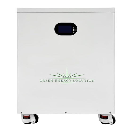
2. Product description 2.1 Product dimension Model Size(L*W*H) MB51400-300A-HWB 500*560*730mm... -
Page 6: Product Details
2.2 Product details Display Air switch Positive and negative poles Power Switch Communication Board... -
Page 7: Electrical Schematic Diagram
2.3 Electrical schematic diagram 3. Technical specifications Project Model MB51400-300A-HWB Nominal capacity 400AH Nominal voltage 51.2V Charging voltage 56.8-57.6V Operating voltage 43.2V~58.4V Charging current At a temperature of 25°C, charge to 58.4V with a constant current of 0.2C 5A, and then change continuously with a Standard charging mode constant voltage of 58.4V until the current is not greater... -
Page 8: Bms Characteristics
Storage temperature -20°C to 60°C (-4°F to 140°F) @60±25% relative humidity Line joint 350A Self-Locking Fitting Quick Release Connector Net Weight 175.5kg Approx. Communication protocol RS485、RS232、CAN Growatt、Deye、Goodwe、Voltronic power、Sofar、 Support inverter brand VICTRON、Solis、Megarevo、SRNE 4. BMS characteristics 4.1 Instructions for LED lights Four green capacity indicators, a red alarm indicator, a green running indicator and a switch indicator. - Page 9 4.1.2 Status indicator Table 3 Status indicator status table ON/OFF Alert LED Battery Level Indicator explain Warning/Normal/ Status Protection ● ● ● ● ● ● ● Shut Sleep mode Light off down Flash standby normal mode According to the electricity Standby indication Flash...
-
Page 10: Boot And Sleep Mode
4.2 Boot and sleep mode Sleep mode: the battery will be in sleep mode if any of the following conditions are met The battery or battery pack over discharge protection lasts for 30 seconds and is not released. Press the power on / off button for 3 seconds and release. The minimum voltage of the battery is lower than the "sleep voltage"... -
Page 11: Communication Area
4.3 Communication area RS232: BMS can communicate with upper computer through RS232 interface, so as to monitor various information of battery, including battery voltage, current,temperature, status and battery production information, etc. the default baud rate is 9600bps. RS485: with dual RS485 interface, you can view the information of pack. The default baud rate is 9600bps.If it is necessary to communicate with the monitoring equipment through RS485, the monitoring equipment is used as the host, polling data according to the address, and the address setting range is 1 ~ 15. - Page 12 Definition of electrical interface RS232 -- 6P6C vertical RJ11 plug RJ11 pin Definition Description TX(Single board) RX(Single board) Table 5 RS485 and CAN Interface RS485 - 8P8C vertical RJ45 socket CAN - 8P8C vertical RJ45 socket RJ45 pin Definition Description RJ45 pin Definition Description 1、8...
-
Page 13: Description Of Parallel Connection
5. Description of parallel connection 5.1 Parallel Connection Diagram If parallel batteries are required, connect the wires according to the diagram,maximum support for 15 batteries in parallel 5.2 Communication line parallel diagram The signal line connected to the inverter should use RS485 communication line or CAN communication line. - Page 14 Table 4 The Dial Switch Setting Table Address Dial switch position Communication line parallel diagram...
-
Page 15: Operating Instructions
6. Operating instructions 6.1 Operating instructions of the display screen 6.1.1 Introduction of LCD Display Button Description: MENU: enter the management system. ENTER: enter the submenu. DOWN: moves the cursor down or to the next page. ESC: returns to the previous one 6.1.2 Boot screen Battery protection status: Overvoltage: OV... - Page 16 Move the cursor to "temperature" and press "enter" to check the battery temperature information, then press "down" to turn the page XX℃ XX℃ XX℃ XX℃ PCB-T XX℃ ENV-T XX℃ Move the cursor to "cell voltage" and press "enter" to check the battery voltage information, then press "down"...
- Page 17 page Status Record 》 BMS Status 》 Move the cursor to "Record", then press "Enter" to check the battery alarm information, then press "DOWN" to turn the page. 0/UTP Move the cursor to "BMS Status", then press "Enter" to check the battery protection information, and then press "DOWN"...
-
Page 18: Product List And Tools
Move the cursor to "Sys Setting", then press Enter to check the version information, and then press "▼" to turn the page. Hibernation and activation functions After 1 minute of button-free operation in normal operation, the display will turn off (backlight only), and pressing any button while the screen is off will allow the screen to light up and function normally. -
Page 19: Instruction Manual
8. Instruction manual Place the battery in an appropriate position, plug the positive/negative connector into the positive/negative socket. Connect the other end of the positive and negative lead to the inverter. Turn on the Rocker switch and the Air Switch.
Need help?
Do you have a question about the MB51400-300A-HWB and is the answer not in the manual?
Questions and answers