
Summary of Contents for nVent SCHROFF FCM3
- Page 1 SCHROFF Fan Control Module FCM3 User Manual Release 1.0 03.02.2024 Doc-No.: 63972-448...
- Page 2 Schroff GmbH Langenalber Str. 96-100 75334 Straubenhardt/Germany schroff.nVent.com This document is furnished under license and may be used or copied only in accordance with the terms of such license. The content of this manual is subject to change without notice. nVent assumes no responsibility or liability for any errors or inaccuracies that may appear in this book.
-
Page 3: Table Of Contents
Table of contents Safety Intended Use Safety instructions of the manufacturer Disclaimer Safety symbols used in this manual Safety Information for the Operator FCM3 Overview Overview Connectors Operation Fan Curve and Alarms Fan curve Alarms Over temperature alarm Fan fail alarm... -
Page 4: Safety
1 Safety Intended Use The Fan Control Module 3 (FCM3) is a stand-alone fan controller to control and monitor up to 6 fans. Intended use includes compliance with the terms and conditions for assembly, disassembly, commissioning and operation specified by the manufacturer. -
Page 5: Safety Symbols Used In This Manual
Safety symbols used in this manual In these original operating instructions, warning notices point out residual risks that cannot be avoided by constructive means when installing or operating the fan tray. The warning notices are classified according to the severity of the damage occurring and the probability of its occurrence. ⚠... -
Page 6: Safety Information For The Operator
This equipment is not suitable for use in locations where children are likely to be present. Read manual The nVent SCHROFF Fan Control Module FCM3 intended to be installed and maintained by qualified and trained personnel in compliance with local and national electrical codes... -
Page 7: Fcm3 Overview
2 FCM3 Overview Features: • Monitors and controls up to 6 fans • PWM Control • Monitors the signals from up to 6 temperature sensors • Can monitor the presence of a 3.3 V, 5 V, 12/24 V and -12 V voltage •... -
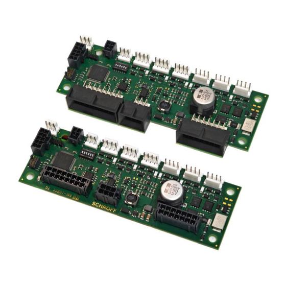
Page 8: Overview
Overview... -
Page 9: Connectors
3 Connectors Part No. Mating Connector Manufacturer Manuf. Part No 23207172 X116 Molex 43025-1600 23207172 X103 Molex 43025-0600 23207172 X115 Molex 43025-1400 23207170 X105 Molex 44133-1600 23207170 X117 Molex 44133-0600 23207170 X107 Molex 44133-1400 23207170 /172 X104 Molex 105308-1210 23207170 /172 X100 Molex 105308-1204... -
Page 10: Operation
5 °C , the output for the temperature fail LED and a digital output are activated. The FCM3 can monitor up to 6 fan tacho signals and can control the fans as a group by a PWM signal. The FCM3 performs every minute a fan behavior test. -
Page 11: Fan Curve And Alarms
5 Fan Curve and Alarms Fan curve The speed of the fans is controlled via a curve depending on the temperature of the NTC sensors. The reading of the NTC sensor with the highest temperature is used as a reference. The temperature curve can be selected via the DIP switch SW100 or SMBus. -
Page 12: Alarms
Alarms The FCM3 has overtemperature and fan fail alarms. The alarms are signaled via an optional display, open collector outputs (max. 50 mA) or SMBus. Display Example Fan Fail optocoupler Over temperature alarm If a NTC sensor temperature exceeds the maximum temperature of the selected fan curve by 5 °C , the red temperature TEMP LED and an open collector output are activated and the resp. -
Page 13: Display
There are 2 different displays available. The legacy display Part No.: 23204-883 with 6 LEDs and labeling: The legacy display can only be connected to the FCM3 with an adapter board Part No.: 23207-167. The current display Part No.: 23207-168 with 6 SMD LEDs For the current display light pipes must be installed in the system. -
Page 14: Using The Voltage Status Leds
Using the voltage status LEDs The displays provide 4 LEDs for the status of 4 voltages (3.3 V, 5 V, 12 V, -12 V). To use this functionality, the corresponding voltages must be connected to connector X115/X107. The 12 V input or the 12 V LED can also monitor a voltage of 24 V. To monitor 24 V, bit 5 on the DIP switch SW100 must be set. -
Page 15: Control And Monitoring Via Smbus
The fan controller can hold down the clock to reduce the bus speed and supports SMBus standard mode up to 100 kbit/s. See the following table which parameters can be read or set via SMBus. FCM3 SMBus Register Description SMBus Transaction Type: Command Name... -
Page 16: Configuration Status
Bit 5 == '0': Temperature NTC 6 ok … Bit 0 == '0': Temperature NTC 1 ok Bit 5 == '1': Temperature NTC 6 failed … Bit 0 == '1': Temperature NTC 1 TEMP_FAIL READ Byte failed 28h - RESERVED Fans FAN_TACHO_1 Read Word... - Page 17 CHANGE_ENABLE is set SERIAL_NUMBER Write Byte Read Byte EEPROM to "42" FIRMWARE_NUMBER Read Byte Firmware number of the FCM3 9Eh - RESERVED Value = 42: PRODUCT_NUMBER, SERIAL_NUMBER and FIRMWARE NUMBER can be changed Value != 42: PRODUCT_NUMBER, SERIAL_NUMBER and...
-
Page 18: Mounting
6 Mounting To mount the FCM3 inside a system, Schroff recommends to use locking supports, as example ETTINGER Part No.: 006.27.086... -
Page 19: Initial Operation
The current at one fan connector (X108-X113) must not exceed 3 A. The FCM3 has 2 connectors, each with 2 pins for the fan power supply. If the current consumption of the fans is <10 A, 2 pins must be connected to at least one connector; if the current consumption of the fans is >... - Page 20 Initial operation: • Mount the FCM3 inside your system • Connect the power supply but don’t switch the power on • Connect all fans and temperature sensors. • Connect the display with the LEDs • Set the jumper X106 to learning mode (position 1-2).
-
Page 21: Technical Data
0 °C ..+70 °C -40 °C … +85 °C Ambient Temperature Storage 20 – 80 % RH non-condensing Humidity Part Numbers FCM3, Connector X105, X107, X117 90° 23207-170 FCM3, Connector X103, X115, X116 180° 23207-172 NTC Sensor with 400 mm cable and 23204-882...
Need help?
Do you have a question about the FCM3 and is the answer not in the manual?
Questions and answers