Advertisement
Available languages
Available languages
Quick Links
Advertisement

Summary of Contents for MALTEC MasterMultimeter
- Page 1 Miernik Prądu MasterMultimeter + Przewody Instrukcja obsługi...
- Page 2 Przed użyciem przyrządu należy uważnie przeczytać niniejszą instrukcję i zachować ją do wykorzystania w przyszłości. 1. Przegląd Ten produkt to multimetr cyfrowy o liczniku 4000 i automatycznym zakresie, z maksymalnym zatrzymaniem MAX, zatrzymaniem danych HOLD, pomiarem temperatury, automatycznym wyłączaniem, podświetleniem, pełnozakresowym zabezpieczeniem przed przeciążeniem i wskaźnikiem zbyt niskiego napięcia akumulatora.
- Page 3 Uziemienie Bezpiecznik Zgodność ze standardami Wspólnoty Europejskiej (UE) Odnosi się do poziomu ochrony przed napięciem impulsowym wytrzymywanym przez przepięcie (instalacyjny) poziom III i stopień zanieczyszczenia 2 zgodnie z normą IEC-61010. Konserwacja Nieprofesjonalnemu personelowi zajmującemu się konserwacją nie wolno otwierać dolnej części obudowy w celu regulacji lub naprawy instrumentu.
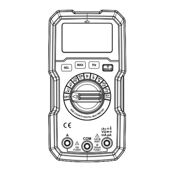
- Page 4 3. Wprowadzenie do instrumentu Schematyczny diagram wyglądu 1. Bezdotykowa sonda do wykrywania napięcia AC NCV 2. wyświetlacz LCD 3. Klawisze funkcyjne 4. Pokrętło zakresu 5. Koniec wejściowy Opis końca wejściowego Koniec Opis wejściowy Wspólny koniec wejściowy (połączony z czarną sondą) Napięcie, rezystancja, pojemność, temperatura, dioda, test włączenia- wyłączenia, identyfikacja przewodu pod napięciem i prąd wejściowy uA mA (połączony z czerwoną...
- Page 5 10 A Koniec wejściowy prądu 10A (połączony z czerwoną sondą) Opis symbolu wyświetlacza Symbol Opis Wskaźnik zbyt niskiego napięcia akumulatora Funkcja automatycznego wyłączania Elektroda ujemna Napięcie prądu przemiennego Napięcie stałe Próba włączania i wyłączania Dioda ° C/ ° F ° C/ ° F TRZYMAĆ...
- Page 6 Kluczowy opis Klucz Opis TRZYMAĆ Zatrzymanie danych MAKS Maksymalne trzymanie Podświetlenie Klawisz wyboru funkcji 4. Przewodnik po operacjach Zatrzymanie danych Klawisz HOLD: krótkie naciśnięcie może zablokować dane pomiarowe, a krótkie naciśnięcie klawisza HOLD ponownie, aby je odblokować. Maksymalne trzymanie MAX MAX Maksimum: Można go używać...
- Page 7 zjawiskiem, gdy końcówka wejściowa „V” i końcówka „COM” znajdują się pod zwarciem przez sondę. Pomiar napięcia stałego (1) Obróć pokrętło zakresu do pozycji ( ) napięcia stałego. (2) Włóż czarną sondę do końca COM i czerwoną sondę do wejścia V. (3) Przesuń...
- Page 8 Podczas pomiaru normalnej diody przyrząd wyświetla wartość spadku napięcia przewodzenia badanej diody wynoszącą około 0,5 V ~ 0,8 V, ale nie przewodzi ona w kierunku odwrotnym. Pomiar pojemności (1) Obróć pokrętło zakresu do pozycji ( ) pojemności. (2) Włóż czarną sondę do końca COM, a czerwoną sondę do wejścia ( ).
- Page 9 Podczas pomiaru prądu ekran nie wyświetla zmierzonej wartości. Sprawdź, czy rurka bezpiecznikowa nie jest przepalona. Jeśli rurka bezpiecznikowa jest uszkodzona, należy ją wymienić na odpowiednią specyfikację, zanim będzie można jej używać w sposób ciągły. Pomiar prądu stałego Gdy napięcie w obwodzie otwartym wynosi 250 V, nie mierz prądu w obwodzie.
- Page 10 (3) Włóż pojedynczą czerwoną sondę do końca wejściowego (pod napięciem), odłącz czarną sondę i włóż czerwoną końcówkę sondy do gniazda zasilania. Jeśli na ekranie pojawi się -H, brzęczyk włączy alarm i zostanie zidentyfikowany jako przewód pod napięciem, przewód zerowy lub przewód uziemiający. Notatka ...
- Page 11 7. Wskaźniki techniczne Napięcie stałe Zakres Rezolucja Dokładność 400mV 0,1 mV 0,001 V ± (0,5% odczytu +5 cyfr) 40 V 0,01 V 400 V 0,1 V ± (0,8% odczytu +5 cyfr) 600 V Impedancja wejściowa: 10M Ω Maksymalne napięcie wejściowe: 600 V Napięcie prądu przemiennego Zakres Rezolucja...
- Page 12 przewodzenia: około 2 V; prąd: około 1mA. Zabezpieczenie przed przeciążeniem: 250V Próba włączania i wyłączania Funkcjonow Zakres Rezolucja Opis Stan testowy ać Jeśli rezystancja jest Napięcie obwodu mniejsza niż 50 Ω , otwartego: około 2 V; 600 omów 0,1 oma rozlegnie się...
- Page 13 4000uA ± (1,0% odczytu +3 cyfry) 400mA 0,1 mA ± (1,2% odczytu +5 cyfr) 10,00A 0,01A Zabezpieczenie przed przeciążeniem: bezpiecznik zakresowy mA (FF600mA/250V): bezpiecznik zakresowy 10A (FF10A/250V). Pasmo przenoszenia: 40 Hz! 1 kHz. 8. Wymiana baterii Aby uniknąć porażenia prądem elektrycznym lub obrażeń ciała na skutek błędnego odczytu, baterię...
- Page 14 Deklaracja CE Malis B. Machoński sp. k. Oświadcza, że urządzenie Maltec MasterMultimeter Current Meter + Cables spełnia wszystkie wymagania dyrektywy EMC 2014/30/EU oraz spełnia następujące normy:...
- Page 15 MasterMultimeter Current Meter + Cables Instruction Manual...
- Page 16 Before using the instrument, please read this manual carefully, and save it well for future using. 1. Overview This product is a 4000-count and auto range digital multimeter with MAX maximum hold, HOLD data hold, temperature measurement, automatic shutdown, backlight, full range overload protection and battery under-voltage indication.
- Page 17 Comply with the standards of the European Community (EU) Refers to the level of pulse withstand voltage protection provided by overvoltage (installation) level III and pollution degree 2 according to IEC-61010 standard. Maintenance Non-professional maintenance personnel are forbidden to open the bottom case to adjust or repair the instrument.
- Page 18 2. LCD display 3. Function keys 4. Range knob 5. Input end Description of input end Input end Description Common input end (connected with black probe) Voltage, resistance, capacitance, temperature, diode, on-off test, live wire identification, and input end of current uA mA (connected with red probe) Input end of current 10A (connected with red probe) Description of display symbol...
- Page 19 Key Description Description HOLD Data hold Maximum hold Backlight Function selection key 4. Operation guide Data hold HOLD key: short press can lock the measurement data, and short press the HOLD key again to unlock it. MAX maximum hold MAX Maximum: It can be used at AC/DC voltage position, AC/DC current position and resistance position to hold the maximum value of measured data, and short press to turn this function on or off.
- Page 20 DC voltage measurement (1) Turn the range knob to ( ) DC voltage position. (2) Insert the black probe into the COM end and the red probe into the V input end. (3) Move the red and black probes to the tested line, and the instrument screen displays the measured value.
- Page 21 Capacitance measurement (1) Turn range knob to ( ) capacitance position. (2) Insert the black probe into the COM end, and the red probe into the ( ) input end. (3) Connect the red and black probes to the measured capacitance, and the instrument displays the measured capacitance value.
- Page 22 When the open circuit voltage is 250V, do not measure the current on the circuit. (1) Turn the range knob to uA/maA/A position. (2) Press the SEL key to DC current function. (3) Insert the black probe into the COM input. Measured value Range Input end connected by the red probe...
- Page 23 6. Technical Parameters Operating height Max 2000m Manual range Display Full range overload protection 250V Maximum display 3999 Over-range indication 0L or – 0L Sampling time About 3 times/sec Automatic shutdown About 20 minutes Backlight About 2 minutes to shut down Power 2 x 1.5V AAA battery Low battery...
- Page 24 AC voltage Range Resolution Accuracy 400mV 0.1mV 0.001V ±(1.0% reading +5 digits) 0.01V 400V 0.1V ±(1.2% reading +5 digits) 600V Input impedance: 10MΩ Maximum input voltage: 600V Frequency response: 40Hz~1kHz Resistance Range Resolution ratio Accuracy 400Ω 0.1Ω 4kΩ 0.001KΩ ±(1.2% reading +5 digits) 40kΩ...
- Page 25 Capacitance Range Resolution Accuracy 400nF 0.1nF 0.001uF ±(3.5% reading +15 digits) 40uF 0.01uF 400uF 0.1uF ±(4.0% reading +20 digits) 0.001mF Overload protection: 250V Temperature Range Resolution Accuracy -20~1000°C 1°C ±(2.0% reading +2 digits) -4~1832°F 1°F ±(2.0% reading +4 digits) Overload protection: 250V DC current Range Resolution...
- Page 26 8. Battery replacement In order to avoid electric shock or personal injury caused by wrong reading, the battery should be replaced immediately when the „ ” symbol appears on the instrument display. Before opening the battery cover to replace the battery, turn the power off and check if the test probe has been disconnected from the measuring circuit.
- Page 27 CE declaration Malis B. Machoński sp. k. Declares that the Maltec device MasterMultimeter Current Meter + Cables meets all the requirements of the EMC 2014/30/EU and meets the following standards:...
- Page 28 MasterMultimeter Strommessgerät + Kabel Bedienungsanleitung...
- Page 29 Lesen Sie dieses Handbuch vor der Verwendung des Instruments sorgfältig durch und bewahren Sie es für die zukünftige Verwendung gut auf. 1. Überblick Bei diesem Produkt handelt es sich um ein digitales Multimeter mit 4000 Zählern und automatischer Bereichswahl, mit MAX-Maximum-Hold, HOLD-Datenhold, Temperaturmessung, automatischer Abschaltung, Hintergrundbeleuchtung, Überlastschutz im gesamten Bereich und Batterie-Unterspannungsanzeige.
- Page 30 Erde Sicherung Entspricht den Standards der Europäischen Gemeinschaft (EU) Bezieht sich auf den Grad des Impulsspannungsschutzes durch Überspannungs-(Installations-)Stufe III und Verschmutzungsgrad 2 gemäß der Norm IEC-61010. Wartung Nicht professionellem Wartungspersonal ist es untersagt, das untere Gehäuse zu öffnen, um Einstellungen oder Reparaturen am Instrument vorzunehmen. ...
- Page 31 3. Geräteeinführung Schematische Darstellung des Aussehens 1. NCV berührungslose Wechselspannungs- Erkennungssonde 2. LCD Bildschirm 3. Funktionstasten 4. Bereichsregler 5. Eingangsende Beschreibung des Eingabeendes Eingangsende Beschreibung Gemeinsames Eingangsende (mit schwarzer Sonde verbunden) Spannung, Widerstand, Kapazität, Temperatur, Diode, Ein-Aus-Test, Stromführende Leitungsidentifikation und Eingangsstromende uA mA (verbunden mit roter Sonde) 31/ 41...
- Page 32 10 A Eingangsstromseite 10 A (mit roter Sonde verbunden) Beschreibung der Anzeigesymbole Symbol Beschreibung Batterie-Unterspannungsanzeige Automatische Abschaltfunktion Negative Elektrode Wechselstrom Spannung Gleichspannung Ein-Aus-Test Diode ° C/ ° F ° C/ ° F HALTEN Datenaufnahme Maximaler Halt Berührungslose Wechselspannungserkennung Live Identifizierung stromführender Leitungen Frequenz mV/V Stromspannung...
- Page 33 Schlüsselbeschreibung Schlüssel Beschreibung HALTEN Datenaufnahme Maximaler Halt Hintergrundbeleuchtung Funktionsauswahltaste 4. Bedienerführung Datenaufnahme HOLD-Taste: Durch kurzes Drücken können die Messdaten gesperrt werden, durch erneutes kurzes Drücken der HOLD-Taste werden sie freigegeben. MAX maximaler Halt MAX Maximum: Kann in den Positionen AC/DC-Spannung, AC/DC-Strom und Widerstand verwendet werden, um den Maximalwert der Messdaten festzuhalten.
- Page 34 Im mV-Bereich der Wechselspannung verfügt das Gerät aufgrund der Interferenzen des elektromagnetischen Felds der Umgebung auch dann über eine numerische Anzeige, wenn kein Eingang vorhanden ist oder keine Sonde eingesetzt ist. Es ist normal, Null anzuzeigen, wenn das „V“-Eingangsende und das „COM“-Ende durch eine Sonde kurzgeschlossen sind.
- Page 35 Diodenmessung (1) Drehen Sie den Bereichswähler auf die Diodenposition ( ). (2) Die Taste SEL kurz drücken, um die Diodenposition ( ) anzuzeigen. (3) Stecken Sie die schwarze Sonde in das COM-Ende und die rote Sonde in das ( Eingangsende. (4) Schließen Sie die rote und die schwarze Sonde an die Diode an.
- Page 36 Wert 0 uA bis 4000 uA uA uA/mA 4000 uA bis 400 mA 400 mA bis 10 A 10 A 10 A Notiz Wenn der Strom unbekannt ist, drehen Sie zuerst die Position auf den maximalen Bereich und passen Sie den entsprechenden Bereich entsprechend dem gemessenen Wert an.
- Page 37 (3) Wenn auf dem Bildschirm das NCV-Symbol angezeigt wird, schließen Sie die NCV- Sonde an den Leiter. Wenn die induzierte Spannung niedrig ist, zeigt der Bildschirm -L an, und wenn die induzierte Spannung hoch ist, zeigt der Bildschirm -H an und der Summer gibt Alarme mit unterschiedlichen Frequenzen aus.
- Page 38 Luftfeuchtigkeit bei Lagerung 0 bis 80 % relative Luftfeuchtigkeit Größe 144x73x32mm Gewicht Etwa 146 g (ohne Akku) 7. Technische Indikatoren Gleichspannung Reichweite Auflösung Genauigkeit 400 mV 0,1 mV 0,001 V ± (0,5 % vom Messwert +5 Ziffern) 40 V 0,01 V 400 V 0,1 V ±...
- Page 39 Diode Funktion Reichweite Auflösungsverhält Testbedingung Durchlassspannung im Leerlauf: ca. Diodentest 0,1 V bis 2 V 0,001 V 2 V; Strom: ca. 1 mA. Überlastschutz: 250V Ein-Aus-Test Funktion Reichweite Auflösung Beschreibung Testbedingung Wenn der Widerstand Leerlaufspannung: ca. 2 weniger als 50 Ω V;...
- Page 40 Reichweite Auflösung Genauigkeit 4000 uA 1 uA ± (1,0 % vom Messwert +3 Ziffern) 400 mA 0,1 mA ± (1,2 % vom Messwert +5 Ziffern) 10,00 Uhr 0,01 A Überlastschutz: mA-Bereichssicherung (FF600mA/250V): 10A-Bereichssicherung (FF10A/250V). Frequenzgang: 40 Hz! 1 kHz. 8. Batterieersatz Um einen Stromschlag oder Verletzungen durch falsche Messwerte zu vermeiden, sollte die Batterie sofort ausgetauscht werden, wenn Symbol „...
- Page 41 Verunreinigung, tragen zur Schonung der natürlichen Ressourcen bei und senken die Produktionskosten neuer Geräte. CE-Erklärung Malis B. Machoński sp. k. Erklärt, dass das Maltec-Gerät MasterMultimeter Current Meter + Cables alle Anforderungen der EMV 2014/30/EU erfüllt und die folgenden Normen erfüllt:...
Need help?
Do you have a question about the MasterMultimeter and is the answer not in the manual?
Questions and answers