Advertisement
Advertisement
Table of Contents

Summary of Contents for Verkada ACC-CEL-LTE-2
- Page 1 Install Guide ACC-CEL-LTE-2 Cellular Backup Communicator...
-
Page 2: Product Models
Verkada product is granted under this document. This document may not be sold, resold, licensed or sublicensed and may not be transferred without Verkada’s prior written consent. No part of this document may be reproduced in whole or in part without the express written consent of Verkada. -
Page 3: Introduction What's In The Box
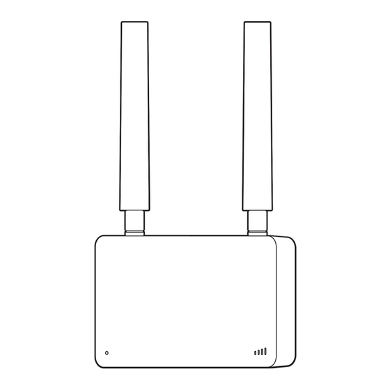
(Pre-installed) What you’ll need Connect Please note: ACC-CEL-LTE needs to be ● #2 Phillips driver (screwdriver or power drill) connected to another Verkada product to ● 7/32 inch (5.5mm) drill bit if using wall function. Please see verkada.com/support anchors compatible products. - Page 4 Introduction Overview Signal Strength Status LED SD Card Slot USB Port Status LED Behaviors Signal Strength LED Behaviors Solid Orange If all LEDs are lit, the connection is optimal. Cellular Backup Communicator is on and booting up. Solid Blue Cellular Backup Communicator is Fewer lights indicate a weaker signal.
-
Page 5: Introduction Technical Specifications
Introduction Technical Specifications Power Consumption .15W standby, 2.5W maximum. (30mA - 500mA current draw) Input Voltage 5VDC Input USB3.0 x 1 I/O Ports Nano SIM holder x 1 LTE: Band 1, 2, 3, 4, 5, 7, 8, 12, 13, 14, 17, 18, 19, 20, 25, 26, 28, 29, 30, 38, 39, 40, 41, 42, 43, 48(CRBS), Bands 66, 71 WCDMA: Band 1, 2, 4, 5, 8, 9... - Page 6 Installation Assembly 1/2 Loosen the security screw, using the T10 Security Torx Screwdriver. Firmly grip the mount plate and pull the blue tab on the Cellular Module to separate.
-
Page 7: Installation & Assembly
Installation Assembly 2/2 Remove the clear protective caps and blue pull tab. To attach the antennas, twist the base. Orient the antenna to desired direction. - Page 8 Installation Mounting 1/2 Thread the USB-A cable through the mount plates square hole and use the appropriate screw holes: A Wall / Ceiling Mount / Single Gang Junction Box B Accessory Mount / EU Junction Box For a solid material like wood or metal, drill ⅛...
-
Page 9: Installation Mounting
Installation Mounting 2/2 Insert the Cellular Module into the mount plate starting with the bottom edge, and snapping the top edge in last. Tighten the security screw, using the T10 Security Torx Screwdriver. Reference the LED status page for the appropriate behaviors after installation. - Page 10 Appendix Compliance This device complies with part 15 of the FCC Rules. Operation is subject to the following two conditions: (1) This device may not cause harmful interference, and (2) this device must accept any interference Compliance received, including interference that may cause undesired operation. NOTE: This equipment has been tested and found to comply with the limits for a Class A digital device, pursuant to part 15 of the FCC Rules.
- Page 11 Appendix Support Thank you for purchasing this Verkada product. If for any reason you're experiencing issues or need assistance, please contact our 24/7 Technical Support Team immediately. Sincerely, The Verkada Team verkada.com/support...
Need help?
Do you have a question about the ACC-CEL-LTE-2 and is the answer not in the manual?
Questions and answers