Advertisement
Quick Links
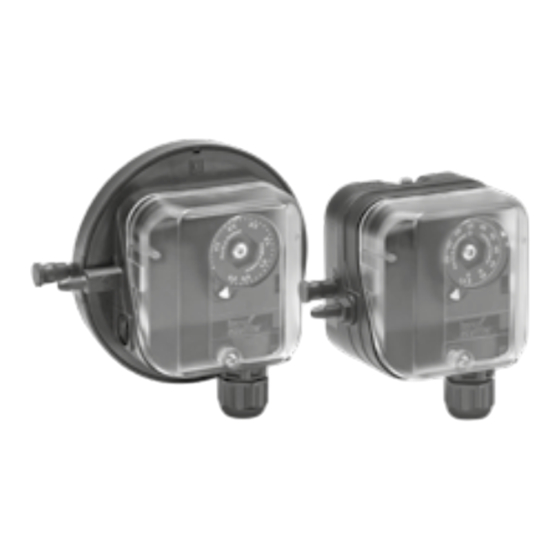
Pressure switches for air DL..A, DL..K
Contents
1 Safety . . . . . . . . . . . . . . . . . . . . . . . . . . . . . . . . 1
2 Checking the usage . . . . . . . . . . . . . . . . . . . . . 2
3 Installation . . . . . . . . . . . . . . . . . . . . . . . . . . . . 2
4 Wiring . . . . . . . . . . . . . . . . . . . . . . . . . . . . . . . . 4
5 Adjustment. . . . . . . . . . . . . . . . . . . . . . . . . . . . 5
6 Function check. . . . . . . . . . . . . . . . . . . . . . . . . 6
7 Accessories . . . . . . . . . . . . . . . . . . . . . . . . . . . 6
8 Technical data . . . . . . . . . . . . . . . . . . . . . . . . . 6
9 Designed lifetime . . . . . . . . . . . . . . . . . . . . . . . 7
10 Certification . . . . . . . . . . . . . . . . . . . . . . . . . . 7
11 Logistics . . . . . . . . . . . . . . . . . . . . . . . . . . . . . 8
12 Disposal . . . . . . . . . . . . . . . . . . . . . . . . . . . . . 8
oPeRAtInG InstRUCtIons
Cert. Version 04.24 · Edition 12.24 · EN · 34425501
1 sAFetY
1.1 Please read and keep in a safe place
Please read through these instructions
carefully before installing or operating. Following the
installation, pass the instructions on to the operator.
This unit must be installed and commissioned in
accordance with the regulations and standards in
force. These instructions can also be found at www.
docuthek.com.
1.2 explanation of symbols
1 , 2 , 3 , a , b , c = Action
➔ = Instruction
1.3 Liability
We will not be held liable for damage resulting from
non-observance of the instructions and non-com-
pliant use.
1.4 safety instructions
Information that is relevant for safety is indicated in
the instructions as follows:
DAnGeR
Indicates potentially fatal situations.
WARnInG
Indicates possible danger to life and limb.
CAUtIon
Indicates possible material damage.
All interventions may only be carried out by qualified
gas technicians. Electrical interventions may only be
carried out by qualified electricians.
1.5 Conversion, spare parts
All technical changes are prohibited. Only use OEM
spare parts.
Advertisement

Related Manuals for krom schroeder DL A Series


Summary of Contents for krom schroeder DL A Series
- Page 1 Pressure switches for air DL..A, DL..K oPeRAtInG InstRUCtIons Cert. Version 04.24 · Edition 12.24 · EN · 34425501 1 sAFetY 1.1 Please read and keep in a safe place Please read through these instructions carefully before installing or operating. Following the installation, pass the instructions on to the operator.
- Page 2 2.3 type label 2 CHeCKInG tHe UsAGe DL 1,5–3A, DL 3K, DL 5–150A, DL 5–150K D-49018 Osnabrück, Germany For monitoring positive, negative or differential pres- sures of air, flue gas or other non-aggressive gases. This function is only guaranteed when used within the specified limits – see page 6 (8 Technical data).
- Page 3 3.1 Installation position 49,5 (1.9") ø 2,7 x 8 ø 3,5 x 8 (ø 0.11" x 0.3") (ø 0.14" x 0.3") ➔ Installation in the vertical or horizontal position, or DL..A: Rp ¼ sometimes upside down, preferably with vertical (DL..AT: ¼" NPT) diaphragm.
- Page 4 DL 5–150K CAUtIon – To ensure that the DL..A, DL..K is not damaged during operation, note the switching capacity, 2 = ø 4,75 x 1 mm (+) see page 6 (8 Technical data). 3 = ø 4,75 x 1 mm (-) In the case of low switching capacities, such as (5 = ø...
- Page 5 Max. inlet Mean Adjusting pres- switching range sure differential Pa (mbar) NC 1 Pa (mbar) (mbar) NO 2 DL 5A, 40–600 20–30 DL 5K (0.4–6) (300) (0.2–0.3) In the positive adjusting range, remove the template DL 5AT, 50–500 20–30 and wire the unit as shown in the engraved connec- DL 5KT (0.5–5) (300)
- Page 6 6 FUnCtIon CHeCK NO 2 We recommend a function check once a year. 1 Press the test key during operation – the pressure switch switches. TEST 2 In case of differential pressure, press both keys simultaneously. – TEST 7.2 Red/green LeD for 24 V DC/AC or 110– TEST 230 V AC 24 V DC, I = 16 mA;...
- Page 7 The set switching point may noticeably change in media and ambient temperatures below -30°C (cos φ = 1) (cos φ = 0.6) (-22°F). Check product suitability. < 30 V AC/ DL..TG 0.1 A 0.05 A Storage and transport temperatures: -20 to +40°C (-4 to +104°F). Contact gap < 3 mm (μ). Micro switch to EN 61058-1.
- Page 8 10.3 UKCA certified than this, the overall service life will be reduced by the corresponding amount of extra storage time. 12 DIsPosAL Gas Appliances (Product Safety and Metrology etc. Devices with electronic components: (Amendment etc.) (EU Exit) Regulations 2019) Weee Directive 2012/19/eU – Waste electrical BS EN 1854:2010 and electronic equipment Directive 10.4 FM and AGA approval, UL listing, eurasian...
Need help?
Do you have a question about the DL A Series and is the answer not in the manual?
Questions and answers