Table of Contents
Advertisement
Quick Links
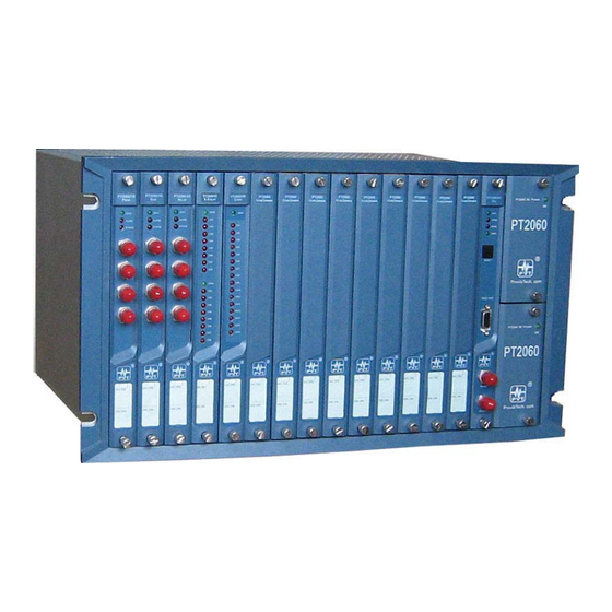
PT2060 Monitor
PT2060/10 PROX Proximity Module
User Manual
Installation, Operation, Maintenance
ProvibTech, Inc.
11011 Brooklet Drive, Suite 300, Houston, Texas 77099, USA
Phone: +1-713-830-7601, Fax: +1-281-754-4972, Email:
pvt@provibtech.com
, Web:
www.provibtech.com
PT2060-10-USR-A-11
COPY RIGHT PROVIBTECH 2007
Advertisement
Table of Contents

Summary of Contents for Provib Tech PT2060
- Page 1 PT2060 Monitor PT2060/10 PROX Proximity Module User Manual Installation, Operation, Maintenance ProvibTech, Inc. 11011 Brooklet Drive, Suite 300, Houston, Texas 77099, USA Phone: +1-713-830-7601, Fax: +1-281-754-4972, Email: pvt@provibtech.com , Web: www.provibtech.com PT2060-10-USR-A-11 COPY RIGHT PROVIBTECH 2007...
-
Page 2: Table Of Contents
PT2060/10 PROX Proxinity Module Contents Receiving Inspection and Handling Guide......................3 Inspection ..............................3 Handling and Storing Considerations......................3 PT2060/10 Module Introduction ........................4 General Information............................ 4 Module Description............................. 7 Hardware............................. 7 Software .............................. 8 Specification ............................... 8 Electrical.............................. 8 Environmental ........................... -
Page 3: Receiving Inspection And Handling Guide
Handling and Storing Considerations PT2060 should be handled with care during unpacking and installation. Damage to PT2060 is typically caused by rough handling, shock, or electrostatic discharge (ESD). Be aware of the following precautions when unpacking and handling PT2060 rack or any module. -
Page 4: Pt2060/10 Module Introduction
ProvibTech’s PT2060/10 PROX proximity module is a four channel proximity signal conditioner, and processing unit. This module should be assembled in the PT2060 rack to fulfill its function. The PT2060 System Configuration software is used to configure the module’s type, and set its parameters and display information including active value. - Page 5 Many machines require a turning gear be used to prevent rotor bow while the machine is off-line. It is essential that the rotor speed of operation has dropped to a specified value, which is zero speed. PT2060/10 PROX proximity module continuously measures shaft speed, and zero speed indication.
- Page 6 A standard 19″ PT2060 rack can contain maximum three sub-systems. Each system has to be on slot 1-4, slot 5-8 and slot 9-12. PT2060/43 R-RELAY module can be mounted in slot 4, 8 and 12 only. Three PT2060/10 PROX modules must be assembled in three adjacent slots, slot 1-3 for example, together with a PT2060/43 R-RELAY module assembled in slot 4 to constitute a TMR system.
-
Page 7: Module Description
One PT2060/10-Front and one PT2060/10-Back constitute a PT2060/10 PROX proximity module. The module has on board status indication. There are three LEDs on PT2060/10-Front panel that display different status of the monitoring channels. There are four buffered output BNCs that corresponding to its four channels. -
Page 8: Software
PT2060/10 PROX modules. PT2060/10 can be configured to different mode. Full scales, alarms set points, alarm delay etc. can also be field configured. In addition, 4-20mA output can be calibrated. Real-time signal acquired and processed by the PT2060/10 PROX module can be displayed in the software. - Page 9 Speed / Zero speed Signal Conditioning: Frequency Response: The PT2060/10 module will support 1 - 255 events per revolution with a maximum full scale range of 60000 RPM, and a maximum input frequency of 10 kHz. Minimum input frequency for proximity transducers is 0.0167 Hz (1 RPM for 1 event/revolution) and for magnetic pickups (Speed signal...
- Page 10 4-20mA will not affect system performance. Maximum load: 300Ω Resolution: Less than 0.33% FS Buffered Output: On PT2060/10-Front panel, each channel has one BNC connector. The output is the unfiltered raw signal. Output impedance: 550Ω Maximum distance: 300m (1000ft) Transducer Power: -24VDC, current limited.
-
Page 11: Environmental
℃ ℃ Humidity: 95% non-condensing Physical Each module comes with two components, the PT2060/10-Front assembly and the PT2060/10-Back assembly. Dimension: 241mm (9.5in)×24.5mm(0.96in) For 19″ rack, they can be mounted in any slot from 1 to 12. For 12″ rack, they can be mounted in any slot from 1 to 6. -
Page 12: Module Configuration And Channel Set-Up
This communication is normally setup via. PT2060/91, the system interface module. As Figure 4 shows, Computer will connects PT2060/91, the System Interface Module via the RS232 on the front panel or RS485 or RS232 on the back panel. Please consult PT2060/91 SIM user manual for more details. -
Page 13: Module Type And Channel Configuration Setting
Module Type and Channel Configuration Setting Configuration Software General Operation PT2060 System Configure software is an important part of test and maintenance of PT2060. Via the software, PT2060 parameters are configured and the running status is displayed. For more detailed information, please refer to PT2060 System Configure software user manual. - Page 14 Figure 7 Figure 8 Menu item Rack relates to rack operations. Its sub items are listed below. Rack Clock Setup Configure system clock of the PT2060 rack. Rack Reset Setup Reset all alarms of the PT2060 rack. Factory Information Operations related to factory information.
- Page 15 Its sub item Real-time Value and Status is used to display the messages of all channels. Sub item Modbus Range Setup is used to set a coefficient to PT2060 in order to make it compatible with other devices based on the standard Modbus.
-
Page 16: Module Function Description
Alert can be configured to one of the two alarm types, Alert and Gap, if the chosen type is Alert, in Real-time value and Status window of PT2060 System Configuration software, the column Alert indicates whether it is in alert status, and the column Danger indicates whether it is in danger status. If the chosen type is GAP, in the software window, the column Alert indicates whether the GAP voltage exceeds the assigned value and the column Danger indicates whether it is in danger status. -
Page 17: Parameter Configuration
The function of trip-multiply is fulfilled through software under the hardware control i.e. the software multiply function takes effect only after a multiply terminal has been plugged in the socket on the PT2060/91 SIM System Interface module. When alert alarm type is Alert, this function is valid for both alarm levels alert and danger. - Page 18 Download or upload the configuration information according to the need. It needs configuration password when first download or upload. The default configuration password is 1234. Warning PT2060 is unable to alarm and protect in configuration status!!! Application Advisory ProvibTech recommends strongly that the original configuration setting must be uploaded and saved before performing any modifications to PT2060 parameters.
- Page 19 PT2060/10 PROX proximity module supports proximity probe input, shaft vibration output. The proximity probe is mounted along the radial direction, i.e. the probe is perpendicular to the shaft. A PT2060/10 PROX proximity module can support 4 shaft vibration measuring channels. Typical full scale can be 100, 125, 200, 250, 500, 1000μm or 5, 10, 20, 40mil for 8mm probe.
- Page 20 The latching mode allows you to know if an alarm set-point has been exceeded since the last rack reset. Press the reset button on the rack SIM module will reset all latched alarms in the PT2060 rack if the current proportional value is less than the set-point value.
- Page 21 Gap alarm has two levels too. Default factory setting of GAP high is -19V, GAP low -1V. When the alarm condition is satisfied, PT2060 goes in alarm status. The figure below is an example of PT2060/10 PROX proximity module shaft vibration configuration setting. Figure 16 Shaft Position Mode Type Setting and Parameter Configuration PT2060/10 PROX proximity module supports proximity probe input, shaft position output mode.
- Page 22 PT2060/10 PROX Proxinity Module TM0180/9m TM0105/5m TM0105/9m TM0110/5m TM0110/9m 3300/8mm/5m, 5mm/5m 3300/8mm/9m, 5mm/9m 7200/8mm/5m, 5mm/5m 7200/8mm /9m, 5mm/9m 3300/11mm/5m 3300/11mm/9m 7200/11mm/5m 7200/11mm/9m Other 8mm Proximity probe transducer Other 5mm Proximity probe transducer Other 11mm Proximity probe transducer Users could choose different probes according to their concrete applications. TM0180/5m is the default transducer.
- Page 23 "away". The default direction is “Toward Probe” for shaft position measuring mode. User could modify it if necessary. The figure below is an example of PT2060/10 PROX proximity module shaft position configuration setting. Figure 17 Differential Expansion Mode Type and Parameter Configuration PT2060/10 PROX modules support proximity probe input, differential expansion output mode.
- Page 24 PT2060/10 PROX Proxinity Module transducer. Transducer Sensitivity When TM0120 is the default transducer, the default value is 0.8mv/um. Alert Time Delay, Danger Time Delay The default value for Alert Time Delay is 3 seconds, and for Danger Time Delay is 1 second. User can modify them from 1s to 60s as need.
- Page 25 Eccentricity Mode Type and Parameter Configuration PT2060/10 PROX modules support proximity probe input, eccentricity output mode. To work in this mode, two channels must be grouped. Channel 1, 2 form a group and channel 3, 4 form another. The first channel of the group need connect to transducer.
- Page 26 PT2060/10 PROX Proxinity Module Proximity probe input, eccentricity output. Transducer Type There are many models of transducers can be connected such as: TM0180/5m TM0180/9m TM0105/5m TM0105/9m TM0110/5m TM0110/9m 3300/8mm/5m, 5mm/5m 3300/8mm/9m, 5mm/9m 7200/8mm/5m, 5mm/5m 7200/8mm /9m, 5mm/9m 3300/11mm/5m 3300/11mm/9m 7200/11mm/5m...
- Page 27 PR can constitute redundant phase reference in which Primary PR is used as the main phase reference signal and is firstly considered by PT2060/10, while Backup PR is used as the secondary phase signal to replace the Primary PR when it is not OK or lost. For example, when user selects with Phase Reference 1 for Primary PR, with Phase Reference 2 for Backup PR, phase reference 1 is used as the phase signal firstly and is checked by PT2060.
- Page 28 PT2060/10 PROX Proxinity Module Figure 19 Figure 20 ProvibTech Phone: +1-713-830-7601 Fax: +1-281-754-4972 sales@provibtech.com , www.provibtech.com...
- Page 29 PT2060/10 PROX Proxinity Module Low Frequency Vibration Mode Type and Parameter Configuration PT2060/10 PROX modules support proximity probe input, low frequency vibration output mode. It is used to monitor low frequent machines, such as hydraulic turbines. Measuring range is 0.5Hz~100Hz. A PT2060/10 PROX proximity module can support up to four low frequency vibration measuring channels.
- Page 30 Speed Mode Type and Parameter Configuration PT2060/10 PROX modules support speed output mode and can be used to monitor shaft rotational speed. Working in this mode, channel 1 and 3 are enabled. This means that only channel 1 and 3 have transducers connected to them.
- Page 31 PT2060/10 PROX Proxinity Module Proximity probe input, Speed output Transducer Type PT2060/10 PROX proximity module can adapt it to many transducer models, including: TM0180/5m TM0180/9m TM0105/5m TM0105/9m TM0110/5m TM0110/9m 3300/8mm/5m, 5mm/5m 3300/8mm/9m, 5mm/9m 7200/8mm/5m, 5mm/5m 7200/8mm /9m, 5mm/9m 3300/11mm/5m 3300/11mm/9m...
- Page 32 Peak Value The maximum speed recorded by the PT2060/10 since the last peak value reset occurred. Click the drop down list Peak Value Setup of menu status/Event to open Peak value window where peak value is present, ProvibTech Phone: +1-713-830-7601 Fax: +1-281-754-4972 sales@provibtech.com , www.provibtech.com...
- Page 33 22 and 23. Figure 22 PT2060/10 retains the peak value even after loss of module power. Click the Reset button in configuration software as the figure 23 shows, the Peak value will be reset to the present speed. Clicking the Reset button can reset the peak values of the current corresponding slots and channels, while Reset All can reset the peak values of all the speed type channels.
- Page 34 PT2060/10 PROX Proxinity Module Zero Speed Mode Type and Parameter Configurations PT2060/10 PROX modules support Zero Speed output mode and can also be used to monitor shaft rotational speed. Working in this mode, channel 1 and 2 are combined together in a group. And channel 3 and 4 are tied together to form another group.
- Page 35 Default factory setting of Danger High or High is 4500 RPM, Alert High or Low is 3000PRM. GAP high is -24V, GAP low is -1V. For any other configuration setting, please refer to Speed. The following figures is an example of PT2060/10 PROX proximity module zero speed configuration setting. Figure 25 ProvibTech Phone: +1-713-830-7601 Fax: +1-281-754-4972 sales@provibtech.com , www.provibtech.com...
- Page 36 Reverse Rotational Speed Mode Type and Parameter Configuration PT2060/10 modules support Reverse rotational speed output measuring mode. In this mode, it is divided into two groups. Channel 1, 2 constitute one group and channel 3, 4 constitute another group. Channel 1 and 3 are normal speed channel.
- Page 37 Real-time Value and Status window of the software. The Alert value turns true, that means it is in reverse rotation state. Accordingly, the Alarm LED on PT2060/10-Front panel is on. When the Alert value in the software window turns False, it means that the signals are in forward rotation state.
- Page 38 PT2060/10 PROX Proxinity Module Teeth Per Cycle Teeth number on the gear. The number of input pulses per shaft revolution when observing an integral multi-event signal source, such as a gear. The Events per Revolution may be specified as a number between 1 and 255 with four decimals .
- Page 39 PT2060/10 PROX Proxinity Module Figure 27 Channel 2/4 Channel Type Reverse rotational speed output Transducer Type Refer to Channel 1/3. User should choose it according to actual need. Transducer Sensitivity Refer to Channel 1/3. Teeth Per Cycle The same as channel 1/3.
- Page 40 PT2060/10 PROX Proxinity Module It always is Alert type. Channel Enabled The same as channel 1/3 Alarm Latching The default status is checked. User can modify it. Set Point The alarm thresholds are set here. This type does not support one high alarm, one low alarm mode. There is only one alarm level, Danger High.
-
Page 41: Transducer List
PT2060/10 PROX Proxinity Module Transducer List These are the transducers that can be connected to PT2060/10 PROX proximity module. For transducers not listed on this table, please consult ProvibTech before use. Transducer input Module output TM0180/5m TM0180/9m TM0105/5m TM0105/9m TM0110/5m... -
Page 42: Module Control And Real-Time Monitoring
From the PT2060 System Configuration software the above signals can be monitored. The description in this chapter is based on PT2060 System Configuration. For more details, please refer to PT2060 System Configuration software user manual. - Page 43 PT2060/10 PROX Proxinity Module frequency vibration) and self-test functions. Alarm bypass has two types, software bypass and hardware bypass. The multiply alarm is implemented through the software with a multiply terminal plugged. Self-test is fulfilled under the software control. ProvibTech...
-
Page 44: Hardware Module Operation
Besides software, PT2060/10 PROX modules can also provide messages of the monitored equipments. There are four BUF ports on PT2060/10-Front panel and four current output ports on PT2060/10-Back panel corresponding to its four channels. This figure greatly enhanced PT2060/10 PROX proximity module versatility. -
Page 45: Pt2060/10-Back
PT2060/10 PROX Proxinity Module 1. OK / IO LED 2. Alarm LED 3. Bypass LED 4. Buffered output The four BNC connectors are corresponding to the output of the 1, 2, 3 and 4 channels. The buffered output will output the raw unfiltered sensor signal to portable data collector. - Page 46 PT2060/10 PROX Proxinity Module 1. The terminal for sensor input of channel 1 and channel 2 Figure 33 The screw on top and bottom are used to mount the connector. You may loose the screws, remove the connector, connect the cable and re-mount the connector.
-
Page 47: Field-Wiring Diagram
PT2060/10 PROX Proxinity Module Field-wiring Diagram Field-wiring Diagram for all 5mm, 8mm and 11mm Probe Systems T M 0 1 8 2 POW(-24V) 5mm/8mm Driver SENSITIVITY: 8mV/um 200mV/mil ProvibTech T M 0 1 8 2 POW(-24V) 5mm/8mm Driver SENSITIVITY: 8mV/um... - Page 48 PT2060/10 PROX Proxinity Module Field-wiring Diagram for 25mm Probe System Black White Blue Black White Blue Black White Blue Black White Blue OUT1 OUT2 OUT3 OUT4 SHIELD Figure 36 ProvibTech Phone: +1-713-830-7601 Fax: +1-281-754-4972 sales@provibtech.com , www.provibtech.com...
- Page 49 PT2060/10 PROX Proxinity Module Field-wiring Diagram for Magnetic Pickup Systems White Shield White Shield OUT1 OUT2 OUT3 OUT4 SHIELD Figure 37 ProvibTech Phone: +1-713-830-7601 Fax: +1-281-754-4972 sales@provibtech.com , www.provibtech.com...
- Page 50 PT2060/10 PROX Proxinity Module Field-wiring Diagram for Hazardous Area Application TM0412 used as the barrier. For other barriers, please consult ProvibTech for tech support. T M 0 1 8 2 POW(-24V) 5mm/8mm Driver SENSITIVITY: 8mV/um 200mV/mil ProvibTech OUT1 OUT2 OUT3...
- Page 51 After installing the two probes and connecting to PT2060/10 PROX proximity module, Power on the system. Choose which one is used as the criterion to estimate lead or lag of the signals via the software PT2060 system configuration. Refer to the relevant part of Configuration Setting and Application for operations.
-
Page 52: Module Maintenance
It also covers the linearity verification. But if the module behaves abnormal, user has to replace it by a new one. This part describes how to check PT2060/10 PROX proximity module work status and calibrate output current in the following sections. -
Page 53: Software Preparation
5. Connect PC serial port to PT2060 with a standard communication cable. 6. Power up. Upload all the modules’ information. Save PT2060 configuration setting to a file, Power off the PT2060, demount it from the equipment and transfer it to a workbench. -
Page 54: Module Test
Figure 41 Module Test A PT2060/10 PROX proximity module can accept signal from proximity probes only, no matter what type it works in (Shaft Radial Vibration, Axial Thrust Position, Differential Expansion, Eccentricity, Low Frequency Oscillation, Speed, Zero Speed, reverse rotation). The maintenance steps are all alike, except a bit difference in details. - Page 55 If alarm latch is not set, the alarm will be reset as soon as the input signal is removed. Otherwise, it will be latched and can be reset only by pressing RESET button located on PT2060/91-Front panel (or clicking the menu item Rack->Rack Reset Setup of the software).
- Page 56 Feed a signal higher than alert or danger set-point to a channel. Plug the prepared bypass terminal in the socket located on the back panel of communication module. Bypass LED of the PT2060/10 PROX proximity module should light up and the Alarm LED should go off. Meanwhile, the alarm mark in the Real-time Value and Status window of the software vanishes.
- Page 57 PT2060/10 PROX Proxinity Module Figure 43 13. Test of redundant power Feed channel 1 with a signal corresponding to 50% of Full-Scale. At this time, the output current of this channel is about 12.00±0.16mA. Pull out the lower power module and the output current should keep in this range.
- Page 58 Like linearity test, provide a signal to channel 1. Adjust the magnitude of the signal. If channel 1 or channel 2 alarms, the alarm LED on the PT2060/10-Front should come on. The alarm status could be seen in Real-time Value and Status window.
- Page 59 If transducer type is anyone of proximity probes, take one proximity terminal. Plug the terminal into the PT2060/10-Back panel. Connect the red pen of an ampere meter to OUT pin of the current output port and connect the black pen to GND pin on that port. Set the ampere meter to measure direct current. Feed a signal to the channel through the positive pin of the electrolytic capacitor (220μF/50V) of the terminal.
- Page 60 7. Test of alarm Like the linearity test, feed channel 1 with a signal generator. If a channel becomes alarm status, the alarm LED on the PT2060/10-Front panel should come on. The alarm status could be seen in Real-time Value and Status window.
- Page 61 PT2060/10 PROX Proxinity Module Supply signal through the positive pole of electrolytic capacitor 220μF/50V on the terminal(measure tool). Connect oscillograph to BUF terminal. 2. Test of system power on Refer to speed part. 3. Test of communication Refer to speed part.
-
Page 62: 4-20Ma Output Calibration
Refer to speed part. 4-20mA Output Calibration User should not repair the components inside PT2060/10 PROX modules. However, if the linearity of some channels does not satisfy the requirement according to the test result conducted as described above, user could re-calibrate these channels. - Page 63 PT2060/10 PROX Proxinity Module Figure 45 3. The whole procedure is implemented in the 4-20mA Calibration. Click the button Full-scale low(Zero) Calibration to open the zero calibration window(figure 46). Follow the steps showed in the window to implement calibration. First, click the button Start Calibration in step1. Then read the output current value from multimeter after it settled down.
-
Page 64: Exceptional Module Treatment
In case of finding some exceptions after the test, except the linearity problem which can be solved by calibrating, users should not repaire it by themselves. Users could substitute it with a spare PT2060/10 PROX proximity module and contact with a ProvibTech local office. -
Page 65: Troubleshooting
LED, System event list, Alarm event list are described in this chapter. LED located on the PT2060/10-Front panel are OK / IO LED, Alarm LED, and Bypass LED. They directly indicate the PT2060/10 PROX proximity module working status. If something abnormal, user could analyze it and solve some problems. -
Page 66: Real-Time Value And Status
Figure 50 System Event List The System event list of PT2060/10 PROX proximity module could be seen in the PT2060 System Configuration software. This list contains the recent 500 events. Click menu item Status/Event->System Event of the software to open a new window like the figure below. -
Page 67: Alarm Event List
Click the button Upload at left-bottom corner of the window to obtain the new System events. In the left area, there is a list of upload time which is the time you perform an upload from PT2060 rack. Click one of these items to get its detail event list in the right field. -
Page 68: Exceptional Module Treatment
Click the button Upload at left-bottom corner of the window to obtain the new Alarm events. In the left field, there is a list of upload time which is the time you perform an upload from PT2060 rack. Click one of these items to get its detail event list in the right field. -
Page 69: Additional Information
PT2060-001001: PT2060/10 Back panel Examination The encapsulation of PT2060 can protect modules from all kinds of damage. As soon as the reception, user should examine the conducts whether it is damaged and whether it is caused by transportation. Please contact the carrier, if it happened. - Page 70 PT2060/10 PROX Proxinity Module Proximity Probe Input, Shaft Position Output Channel Type: Proximity probe input, shaft position output Transducer Type: TM0180/5m Channel Enabled: checked Transducer Sensitivity: 8.0mv/μm Alarm Latching: checked Alert Time Delay: Danger High: 700μm Danger Time Delay: Alert High: 500μm...
- Page 71 PT2060/10 PROX Proxinity Module Transducer Type: TM0180/5mm Alarm Latching: checked Transducer Sensitivity: 8.0mv/μm Alert Time Delay: Danger High: 175μm Danger Time Delay: Alert High: 125μm Zero Position (GAP): -10v Alert Low: -125μm Full Scale High: 250μm Danger Low: -175μm Full Scale Low: -250μm...
- Page 72 PT2060/10 PROX Proxinity Module Teeth Per Cycle: Alert Low: 66RPM Hysteresis Voltage: Danger Low: 33RPM Full Scale High: 100RPM GAP High: -24v Full Scale Low: 0RPM GAP Low: Measurement Unit: Threshold Type: Auto Alert Type: Alert Rotative Speed Alarm Type: Two Levels...
- Page 73 PT2060/10 PROX Proxinity Module Warning If measurement type is not specified, PT2060/10 module’s channels are configured in Proximity probe input, shaft vibration output by default. ProvibTech Phone: +1-713-830-7601 Fax: +1-281-754-4972 sales@provibtech.com , www.provibtech.com...
-
Page 74: Appendix
PT2060/10 PROX Proxinity Module Appendix There is some information about making Test Terminals. Terminal for Proximity Probe If the channel is to connect with a proximity probe, the terminal should be made following these steps. Take an 8 pin plug (centre distance 3.8mm) as shown in the figure below. Solder the movable pin of a potentialmeter of 10kΩ... - Page 75 PT2060/10 PROX Proxinity Module Bypass Terminal Take a six pin plug (pin distance 3.8mm), and short RST_BY and GND pins according to the label on PT2060/91-Back. Multiply Terminal Take a six-pin plug (pin distance 3.8mm), and short ALM_MU and GND pins according to the label on PT2060/91-Back.
Need help?
Do you have a question about the PT2060 and is the answer not in the manual?
Questions and answers