
Related Manuals for sielco STL Series

Summary of Contents for sielco STL Series
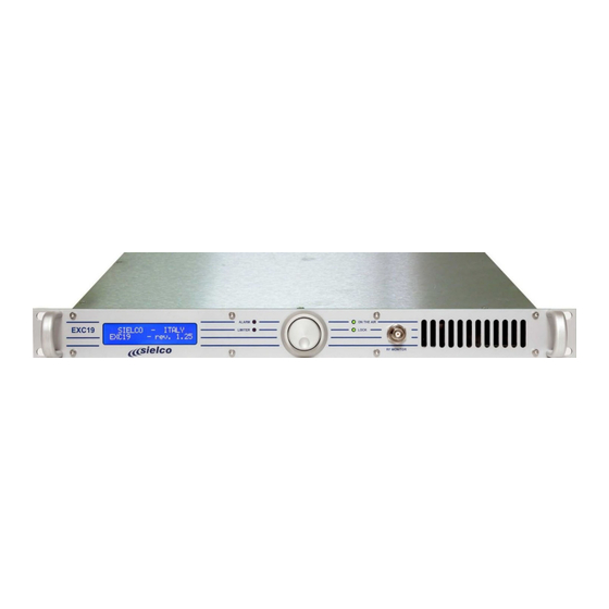
- Page 1 EXC/RTX19 – UHF STL EXC/RTX19 STL family in the upper UHF range 1300 ÷ 2.500 MHz User and Service Manual EXC_RTX19 User Manual eng_v2.10.docx User and service Manual Page 1 of 108...
-
Page 2: Table Of Contents
EXC/RTX19 – UHF STL Summary RELIMINARY NOTES AND LIMITATION OF USE ......................... EU D C) ..................... 5 ECLARATION OF ONFORMITY NTRODUCTION ....................................General ................................6 Project design ..............................6 … S ! ..........................7 IRST OF ALL AFETY Symbols used ..............................7 General warnings .............................. - Page 3 EXC/RTX19 – UHF STL 15.1 Menu flow chart ............................... 48 15.2 Receiver setup menu ............................50 16 M AINTENANCE AND SERVICE ..............................16.1 Basic information ............................. 53 16.2 Warranty ................................53 17 S ERVICE ANUAL ..................................18 I NTERNAL DESCRIPTION OF THE TRANSMITTTER ........................18.1 SEXC26CON, E1244 electric diagram –...
-
Page 4: Preliminary Notes And Limitation Of Use
In the preparation of this manual every effort has been made to provide complete, accurate and up-to-date information, however the information here contained does not represent any commitment on the part of the company. Sielco, in its commitment to constantly improve the quality of its products, reserves the right to change their characteristics without notice. -
Page 5: Eu Declaration Of Conformity (D O C)
EXC/RTX19 – UHF STL EU D ECLARAT ION OF ONFORMITY User and service Manual Page 5 of 108... -
Page 6: Introduction
NT RODUCT ION General The EXC/RTX19 STL series is the result of Sielco's many years of experience and even more of Siel in the production of FM equipment, transmitters, radio links and stereo encoders. These devices have been specifically designed to comply with the most recent international standards as well as with the requirements of the most demanding broadcasters, in order to meet more restrictive specifications than is usually required, while maintaining a reasonable cost. -
Page 7: First Of All ... S Afety
IMPORTANT: Improper use and installation of this equipment could cause even serious damage to things and people. It is therefore necessary that the installer has been authorized by Sielco or its local representative and that both the installer and the user have read the entire manual before carrying out any operation. - Page 8 This manual describes in detail the menus that appear on the LCD display: since the software is continuously updated, some of the screens illustrated in the above chapters may be different from those displayed by the device. If in doubt, contact Sielco.
- Page 9 EXC/RTX19 – UHF STL 4.2.a General safety recommendations When connecting the equipment to the power supply, it is recommended to follow the following rules: This product generally supports a "universal" mains voltage, ie between 100 and 250V~, with a frequency of 50/60Hz. These conditions are met in any EU country and in USA.
- Page 10 EXC/RTX19 – UHF STL 4.2.d Emergency resuscitation technique Step 1 Check the victim for responsiveness. If there is no response, immediately call for medical assistance, and then return to the person. Step 2 Position the person flat on their back. Kneel by their side and place one hand on the forehead and the other under the chin.
-
Page 11: Warnings
If it is really necessary, and after authorization of Sielco srl, very qualified technical staff only can work on or with live parts. In this special case special safety precautions must be taken. Sielco srl declines any responsibility if any safety rule is not respected. The replacement of the accessible fuse must be made with the transmitters turned off and using a fuse with the identical characteristics only as specified by the manufacturer. -
Page 12: Equipment Description , Controls And I/O
EXC/RTX19 – UHF STL QUIPMENT DESCRI PT ION CONTROLS AND The transmitter and receiver devices are housed in the same type of cabinet and are very similar when viewed from the front, differing only in the presence of a ventilation grid on the transmitter. The simple and intuitive functionality of the front panel user interface allows complete control of the device via a single multifunction knob. - Page 13 [20] MPX input - unbalanced BNC input socket of the externally processed stereo composite signal (MPX) (see note). [21] Remote control parallel socket - this Sub-D9 male connector allows you to control the device from a remote location or to perform other functions through appropriate interfacing. The connection standard guarantees compatibility with Sielco devices of previous generations.
- Page 14 EXC/RTX19 – UHF STL Transmitter block diagram User and service Manual Page 14 of 108...
-
Page 15: Receiver
EXC/RTX19 – UHF STL Receiver Correct operation is displayed when the two LOCK and FIELD LEDs turn green. 5.2.a Front LCD display - shows operating parameters and selected functions. In the event of an alarm, the display flashes indicating the type of alarm. - Page 16 [22] Remote control parallel socket - this Sub-D9 male connector allows you to control the device from a remote location or to perform other functions through appropriate interfacing. The connection standard guarantees compatibility with Sielco devices of previous generations.
-
Page 17: Technical Specifications
EXC/RTX19 – UHF STL ECHNICAL SPECIFICAT IONS System Parametro Valore Standard available frequency preset ranges on factory 1350 ÷ 1375 MHz 1370 ÷ 1390 MHz 1429 ÷ 1433 MHz 1510 ÷ 1530 MHz 1660 ÷ 1670 MHz 2367.5 ÷ 2372.5 MHz 2440 ÷... -
Page 18: Rtx19 Receiver Only
EXC/RTX19 – UHF STL Parameter Value Pre-emphasis time constant 0/50/75 µs ±2% S/N (30--20000Hz RMS) >77 dB, 82 typ. mono >74 dB, 77 typ. stereo Modulation distortion, 30--15000 Hz <0.02% @ 75kHz dev. Stereo separation >50 dB (100 ÷ 5000 Hz) >45 dB (30 ÷... -
Page 19: Remote Control Functionality
EXC/RTX19 – UHF STL EMOTE CONTROL FUNCT IONALIT Y Both the devices that make up the radio link are fully controllable in the transmission and reception parameters through the keyboard and the front panel display. The same functions are remotely accessible through the RS232 serial port on the back of the devices. For door control, however, special software is required, which is not included among the standard options, except for simple demonstration programs. -
Page 20: Remote Control Via Lan With Web-Server Or In Snmp
EXC/RTX19 – UHF STL RECEIVER: Pins 1 e 5, ground Pin 2, “modulation presence” signal: The circuit is always of the "open collector" type: a low logic state indicates the presence of modulation on the received signal; on the contrary, a high logic state, + 12V with 10kΩ, signals its absence. As an alternative function it is possible to select from the software the status signaling "blocked on remote control". -
Page 21: Operation Preset
This study must be performed by trained personnel with the necessary experience in this field and is beyond the scope of this manual. Sielco remembers its availability for any clarifications or to analyse and address specific problems that may arise. Installation 8.2.a... -
Page 22: Transmission Of The Rds Or Sca Service From An External Generator
EXC/RTX19 – UHF STL 8.3.b Mono transmission from stereo audio source via internal encoder (optional) Connect both the right (RIGHT) and left (LEFT) input connectors of the STL Tx to the corresponding audio signals as described above. The applied audio signals will pass through the internal channel processor, will be filtered at 15 kHz and pre-emphasized in both channels. - Page 23 EXC/RTX19 – UHF STL Reconnect the previously disconnected signals. 8.4.c Transmission at low power level The radio link transmitter is generally not programmable for output powers lower than 0.5 Watt. In some cases this level can however be lower. 8.4.d Connecting the radio link receiver to the next transmitter In practice, the only connection between the two devices is that of the MPX signal output of the receiver to the corresponding input of the next transmitter, which must be positioned in the "External MPX"...
-
Page 24: Optional Boards
EXC/RTX19 – UHF STL PTIONAL BOARDS The following table summarizes the options available for both the EXC19 transmitter and the RTX19 receiver. Option EXC19 RTX19 Ethernet card for remote control SEXC30REMC SEXC30REMC Stereo encoder SEXC23COD2 EBU/AES digital input card SEXC19DAC RDS Encoder SEX30RDS Stereo decoder with integrated N + 1 management... -
Page 25: Sexc19Dac - Aes Ebu Input Card
EXC/RTX19 – UHF STL SEXC19DAC – AES EBU input card This card allows you to enable the AES EBU input of the EXC19 transmitter. SEXC30RDS – RDS Encoder Optional internal RDS encoder interface card that allows to locally generate the RDS signal in the EXC19 transmitter if not already present in a composite signal coming from the MPX input [19]. -
Page 26: Srtx19Dec2 - Stereo Decoder With Aes Ebu Function
EXC/RTX19 – UHF STL from each other and between that of the receiver's main BF outputs [17] - [20]. On this board there is also the N+1 CONTROL [14] female sub-D9 connector which can be used for the management of channels set up differently for N + 1 systems, by means of a "parallel"... -
Page 27: Srtx19Fi25 - Digital If
IF filters of adequate quality for the performances required in the broadcast field. Those still available are not of adequate quality and would heavily penalize the stereo performance for which Sielco has been known around the world for many years. -
Page 28: Nominal Frequency Deviation , Digital If Filters And Dynamic Selectivity
100 or 125kHz in the second. With Sielco STL transmitters it is immediate to transmit with a modulation lower than the standard 75kHz, since it is easy to check the deviation in kHz on the precise front deviation indicator: however the value expressed in dB is generally still referred to 75kHz where it is equal to 0dB. -
Page 29: Reference Deviation Preset
/ output dynamic range may be limited and / or varied to extremes. This is generally not a problem as long as the value adopted is included in the range +4 ÷ + 9dBm. The default standard for SIELCO is + 6dBm. -
Page 30: Dynamic Selectivity And Digital Signal Processing
LF filters and becomes non-linear. Beyond that point, no IF and LF filters will improve selectivity anymore. Sielco has always designed its radio link Receivers for the best possible selectivity, compatibly with good signal reproduction characteristics in monophony and above all in stereo for repetition with an FM transmitter or further transport in radio link. Until 2015 this was done only with analog circuits and with reasonable compromises between complexity, cost and availability of the components used. -
Page 31: Measurement And Performance Of Dynamic Selectivity
S/N to less than 54dB. The following table compares the typical performances of Dynamic Selectivity on a Sielco STL Receiver fitted with an analog IF card with respect to one fitted with the new digital version. The improvement in selectivity at ± 200kHz (about 30dB) and at ± 300kHz (on average 16dB) is quite evident. - Page 32 +250 +300 Sielco Rx, digital IF Dynamic selectivity in stereo referred to 50kHz deviation, with IF filters designed for 50kHz It is possible to further decrease the deviation, e.g., t0 40kHz while maintaining acceptable characteristics in stereo and still gaining about ten dB with ±...
-
Page 33: Battery Or Dc Voltage Power Supply
ATTERY OR DC VOLTAGE POWER SUPPLY The EXC/RTX19 pair, like all SIELCO radio links, includes external DC power supply terminals with battery for a possible primary or back-up supply in the absence of mains. As standard there is also the automatic charger function when powered from mains. These terminals, nominally for 24Vdc with negative to ground, accept variable input voltages in the range of 22-28Vdc, in the absence of mains voltage. -
Page 34: Sustainable Back-Up And Recharge Time
EXC/RTX19 – UHF STL 11.3 Sustainable back-up and recharge time An estimate of the sustainable back-up time can be easily made assuming that: Manufacturers generally specify the nominal capacity of the battery, when discharged at constant current in 20 hours, rarely in ... -
Page 35: Operative Management Firmware - T X /Rxrev
12.1 introduction The Sielco EXC / RTX19 radio link family is managed in its internal functions by a modern microcontroller (µCU) which controls the various functions based on the user programming, supervises the apparatus, manages the measurement functions. and remote control. -
Page 36: Default Passwords
EXC/RTX19 – UHF STL Also, in this case the factory default setting is "OFF. 12.2.c Level 3 – Higher level of security and factory settings. In this case the password is always “ON” by default, and, for security reasons, it always resets to “ON” after the display time-out, even when disabled. -
Page 37: Description Of Menu And Commands
EXC/RTX19 – UHF STL 13 D ESCRIPTION OF MENU AND COMMANDS To view the operating parameters of the appliance, and to set the latter according to your needs, simply navigate the commands menu indicated by the LCD display. The menu is arranged in a tree, with two main branches arranged vertically. Navigation is simple and intuitive through the single control knob: its rotation allows you to scroll vertically all the menus within the two measurement / control and setup branches. - Page 38 EXC/RTX19 – UHF STL A local time-out will be launched automatically during the “insertion” mode, canceling the inserted data if they are not confirmed within 60 seconds from the last modification. Similarly, 3 minutes after the last modification, the setup branch will automatically exit and the operating modulation control panel will be positioned.
-
Page 39: Exc19 Transmitter Menu
EXC/RTX19 – UHF STL 14 EXC19 TRANSMITTER MENU 14.1 Menu flow chart User and service Manual Page 39 of 108... - Page 40 EXC/RTX19 – UHF STL 14.1.a Start screen The starting screen of the menu is the unnumbered one at the top of the scheme. It is displayed only when the device is turned on, in order to show the firmware version during initialization. In this phase all the LEDs and the display will be switched on and off for testing.
- Page 41 EXC/RTX19 – UHF STL 14.1.e Screen # 02: Direct and reflected power This screen shows the direct power actually delivered and the consequent reflected power. On upper UHF radio links, those in the 1300-2500 MHz range, reflected power is generally not detected. 14.1.f Screen # 03: Multiplex signal level (Output modulation) This picture shows the current modulation peak in dB compared to 75kHz and the actual deviation in kHz.
-
Page 42: Transmitter Setup Menu
EXC/RTX19 – UHF STL The voltages Vs + and Vs- are the same for the whole family of radio link transmitters and are equal to: Vs+ = +12.5±0.3V, Vs – = -12.4V (+1/-2V). The battery voltage is instead: Vbat = +27.4 ± 0.5V with a fully charged battery. In case of battery power, the device works as long as the voltage is between about 22 and 28V. - Page 43 EXC/RTX19 – UHF STL 14.2.b Screen # 22: setup of the transmission frequency In this screen it is possible to vary the operating frequency by editing it in two successive steps, first the part on the left of the comma, the MHz.
- Page 44 EXC/RTX19 – UHF STL If the limiter is on, it is wise not to often exceed the limiter threshold with the audio signal to avoid modulation distortion. 14.2.g Screen # 27: transmission mode and pre-emphasis setup From here you can set the transmission modes (MONO R, STEREO, MONOL + R, EXT MPX) and the preemphasis (0, 25, 50 and 75µs).
- Page 45 EXC/RTX19 – UHF STL password. In this case, the passwords of a lower level must be changed and confirmed: there is however no possibility of knowing what the previous passwords were. From this it follows that it is still possible to change the password and status for example of the 2nd level, even if the relative password is not known, if the 3rd level password is correctly entered, when requested.
- Page 46 EXC/RTX19 – UHF STL TEMPERATURE ALARM! UNLOCK ALARM! HIGH VSWR ALARM! LOW POWER ALARM! NO MODULATION ALARM! OVERMODULATION ALARM 14.2.n Screen # 34: functions and logic levels of the remote I / O pins setup As described in the related section, there are 3 I/O lines that can be assigned to corresponding pins on the parallel remote control connector on the rear panel.
-
Page 47: Factory Menu
The ID is the administrator's login name on the LAN: admin is the factory default. The password is also required for access. The default password assigned by SIELCO for its “admin” is “sielco1”. Both the ID and the password can be freely changed with alphanumeric characters up to a total length of 10. -
Page 48: Rtx19 Receiver Menu
EXC/RTX19 – UHF STL 15 RTX19 RECEIVER MENU 15.1 Menu flow chart The receiver menu is similar to that of the transmitter and is organized in the same way. Many screens are identical and the discussion of these is omitted. Only those that are new or that show some significant variations are described below. User and service Manual Page 48 of 108... - Page 49 EXC/RTX19 – UHF STL 15.1.a Quadro #02: Frequenza e sintonia di ricezione This is the first control screen and shows the working frequency, the tuning of the received signal (T) in kHz with respect to the nominal frequency within just over ± 100kHz and the field strength (F) in dB. In the absence of received signal (Sin <-90dBm) the tuning indication is random.
-
Page 50: Receiver Setup Menu
EXC/RTX19 – UHF STL 15.1.f Screen # 08: Stereo pilot frequency level This screen too is displayed only in case of internal presence of the optional Stereo Decoder board. From here it is possible to control the deviation of the stereo pilot tone at any time with excellent precision without any special maneuvers and without interrupting the modulation. - Page 51 EXC/RTX19 – UHF STL On the first of these two screens it is possible to vary the de-emphasis time constant between 0, 25, 50 and 75µs. On the second screen, on the other hand, the deemphasis function can be activated separately on the monophonic output and on those of the stereo channels, if present.
- Page 52 EXC/RTX19 – UHF STL Outputs: Also in this case the default functions associated with each pin are those present on the first corresponding line. Note that the "FIELD GOOD" function can be indifferently associated with two pins. As for the transmitter, when the device is locked to remote control operation, it is not possible to alter any settings before unlocking this control: in this case, input pin 6 can be associated with a function that allows an external controller to lock remote control operation in addition to the corresponding function on the menu.
-
Page 53: Maintenance And Service
30/35 ° C, that the power supply is carefully examined and possibly replaced after 40-50,000 hours. 16.2 Warranty Like all Sielco-branded solid-state devices, the radio link is guaranteed for one year in all its parts, with the exception of the final power transistor, which could be damaged by an improper output connection. -
Page 54: Service Manual
EXC/RTX19 – UHF STL 17 S ERVICE ANUAL WARNING! THIS SECTION IS ONLY AIMED TO GENERAL EXPLANATION, REFERENCE, AND SERVICE PURPOSE BY SKILLED PERSONNEL. AS EXPLAINED IN THE PREVIOUS SECTIONS, INTERNAL ADJUSTMENTS ARE NOT REQUIRED DURING NORMAL OPERATION. TAMPERING WITH INTERNAL SETTINGS VOIDS THE WARRANTY, MAY HARM THE APPARATUS AND JEOPARDIZE THE GUARANTEED PERFORMAN¬CE. -
Page 55: Internal Description Of The Transmittter
EXC/RTX19 – UHF STL 18 I NTERNAL DESCRIPTION OF THE T RANSMI TTT ER The transmitter EXC19, further referred as “Tx”, includes from 8 to 12 internal modules without counting the display, as can be seen in the "Overall view" drawings and in the "General wiring diagram" drawings, in an appendix to this manual. Some of these modules vary according to the frequency ranges and may not be present on the models for the 1300 ÷... -
Page 56: Sexc18Mb (Or Sexc25Mb), E0837 Diagram - Lf And Rf Control Mainboard
EXC/RTX19 – UHF STL IC1 supplies power to the entire CPU and the logical part of the display. Since this regulator is highly accurate (0.5% error), it is also used as a reference for ADC/DAC/PWM conversions. All components involved in the measurements are at 1% and no adjustment trimmer, except for the fine adjustment of the clock frequency (CT1), is present on the board. -
Page 57: Sexc19Dac, E1245 Diagram - Aes/Ebu Digital Audio Input Interface
EXC/RTX19 – UHF STL Preset the machine to its nominal power at the operating frequency or on the band centre Enable the output power and adjust RT1 to obtain the same power indicated on the display on the external meter. When the Tx works correctly and the control loop is closed, the same reference voltage will be found on TP1 as on TP3. -
Page 58: Sexc19Os13-25, E1226 Diagram - Oscillator In The Bands Between 1300 And 2600Mhz
EXC/RTX19 – UHF STL IC10 is the reference quartz oscillator, while IC11 derives various submultiple frequencies, necessary for the operation of multistep pseudo-digital modulators. IC8 is the main modulator that generates the stereo-multiplex (or mpx) signal with an 8-step synthesis that greatly attenuates the harmonic frequencies generated in the switching process. -
Page 59: Sexc18Al, E1057 Electric Diagram - Auxiliary Power Supply
EXC/RTX19 – UHF STL module with 24Vdc nominal output, 75W rated. Although the nominal voltage is 24V, the regulator is adjusted to + 27.3V in order to function also as battery-charger to any external 24V nominal backup battery, for simple management of them. Be careful to restore this voltage in case of replacement of the power supplies in case of failure or external batteries, if present, will be always engaged and not properly recharged. -
Page 60: Sremcintrf - E1492 Diagram - Cpu And Network Card Interface
EXC/RTX19 – UHF STL 18.12 SREMCINTRF – E1492 diagram - CPU and network card interface This simple, small card allows the direct connection of the SEXC30REMC network card on the transmitter control bus. It contains only two circuits and connects only 3 lines of the network card control connector to the bus. The first one is the +5V power supply, derived from the +12V bus line, via a small, high efficiency switching regulator. -
Page 61: Internal Description Of The Receiver
EXC/RTX19 – UHF STL 19 I NTERNAL DESCRIPTION OF THE RECEIVER The STL receiver (Rx) includes at least 6, often more internal modules, depending on frequency range and options, as can be seen in the "Overall view" drawings and in the "General wiring diagram" attached to this manual. In this case too some modules vary according to the frequency of operation. -
Page 62: Srtx18Mb, E1006 Diagram - Interconnection And I/O Mainboard
EXC/RTX19 – UHF STL the IF filters to conform it to narrower channels and reduced deviation modulation. Filters are implemented for best performance with ± 75kHz (default position), ± 50kHz (mostly used on the American market) and ± 40kHz. In all cases the output voltage is correspondingly amplified to correspond to the same level when the modulation is equal to 100% (0dB) of the chosen nominal value. - Page 63 EXC/RTX19 – UHF STL them. A fourth and a fifth modulator generate a direct current output signal proportional to the level of the pilot frequency and the control signal of the internal oscillator. The time base oscillator is in fact based on a microcontroller (IC18) with a precision 15808kHz quartz oscillator, locked in PLL with the pilot frequency of the MPX signal.
-
Page 64: Operation And Setup At Different Frequency
Unfortunately, the need to adopt a filter as narrow as possible, which is one of the major strengths of Sielco Receivers on these frequencies, does not reconcile with the agility of variation of the reception frequency. In fact, although the receiver may in some cases be programmable over a relatively wide band (20-50MHz, depending on the sub-range of use), the filter is generally only 8- 10MHz wide, or ±... - Page 65 Network Analyzer. Absolutely avoid altering the calibration if you do not have the necessary equipment and training and contact SIELCO assistance if it is necessary to change frequency. The FIL220H08A filter 20.2.a Ref.
- Page 66 EXC/RTX19 – UHF STL Required equipment and tools 20.2.b Spectrum Analyzer with Tracking Generator in band 1300 ÷ 2500 Pair of short cables (~ 20cm) with N connector on one side and SMA on the other. Recommended cable RG223 (50 ohm) SMA female / female feedthrough connector 8mm hex and star key 3mm L-shaped hex key (Allen key) or corresponding...
- Page 67 EXC/RTX19 – UHF STL Adjustment 20.2.d The procedure described does not involve the variation of the intercavity coupling (the 3 upper rods) which must not be altered, nor the adjustment of the input/output matching (the two trimmers close to the connectors) because it does not change for such small tuning.
- Page 68 EXC/RTX19 – UHF STL Adjust the second innermost cavity to resonate close to the first. Second cavity tuning Repeat the tuning with the 2 remaining outermost cavities. Slightly retouch all the 4 rods to obtain a symmetrical function, as flat as possible in the passband, with minimal loss in the centre.
- Page 69 EXC/RTX19 – UHF STL Increase the screen resolution for the final calibration: in the figure the span has been brought to 20MHz (2MHz/div) and the vertical resolution to 5dB/div. Make the final touches to minimize the loss of the filter (in the figure about 1.5dB), make it flat and symmetrical. Tighten the nuts well with the Phillips wrench, while keeping the tuning rods still with the Allen key and check that the tuning does not shift during the operation.
-
Page 70: Exc19 Transmitter - Electrical Diagrams And Component Layout
If in doubt, ask the manufacturer for information. Many SMT technology signal boards cannot be repaired but only replaced with other similar spare parts tested in the factory. Sielco reserves the right at any time to vary the components and their value as required for production and for improving specifications. - Page 71 EXC/RTX19 – UHF STL EXC19 transmitter, 1300-2500 MHz – Assembly view ALARM ON THE AIR EXC19 LIMITER LOCK RF MONITOR User and service Manual Page 71 of 108...
- Page 72 EXC/RTX19 – UHF STL EXC19 transmitter, 1300-2500 MHz – E1243 General electrical diagram User and service Manual Page 72 of 108...
- Page 73 EXC/RTX19 – UHF STL SEXC26CON – System & display CPU board – E1244 electrical diagram User and service Manual Page 73 of 108...
- Page 74 EXC/RTX19 – UHF STL SEXC26CON – System & display CPU board – Component layout User and service Manual Page 74 of 108...
- Page 75 EXC/RTX19 – UHF STL SEXC25MB – Mainboard, I/O and RF control section - E0837M1 electrical diagram (1 of 2) User and service Manual Page 75 of 108...
- Page 76 EXC/RTX19 – UHF STL SEXC25MB – Mainboard, LF process section - E0837M1 electrical diagram (2 of 2) User and service Manual Page 76 of 108...
- Page 77 EXC/RTX19 – UHF STL SEXC25MB – Mainboard - Component layout User and service Manual Page 77 of 108...
- Page 78 EXC/RTX19 – UHF STL SEXC18OS25 – Synthesized oscillator 1300-2600MHz – E1226 electrical diagram Mechanical layout User and service Manual Page 78 of 108...
- Page 79 EXC/RTX19 – UHF STL ASEXC18A20 – 2GHz RF Power Amplifier – E1045 electrical diagram User and service Manual Page 79 of 108...
- Page 80 EXC/RTX19 – UHF STL ASEXC18A20 – 2GHz RF Power Amplifier – Component layout User and service Manual Page 80 of 108...
- Page 81 EXC/RTX19 – UHF STL SEXC23COD2 – Stereo encoder board – E0868 electrical diagram User and service Manual Page 81 of 108...
- Page 82 EXC/RTX19 – UHF STL SEXC23COD2 – Stereo encoder board – Component layout User and service Manual Page 82 of 108...
- Page 83 EXC/RTX19 – UHF STL MODRLS7524 – Switch Mode Power supply Specifications: Input: 90-260Vac 47/60Hz Output: 27,3Vcc / 3.0A User and service Manual Page 83 of 108...
- Page 84 EXC/RTX19 – UHF STL SEXC18AL – Auxiliary ±12.5V regulator and battery manager E1057 electrical diagram and component layout User and service Manual Page 84 of 108...
- Page 85 EXC/RTX19 – UHF STL SEXC19DAC – Digital AES/EBU and analogic LF input board E1245M electrical diagram and component layout User and service Manual Page 85 of 108...
- Page 86 EXC/RTX19 – UHF STL SREMCINTRF – Ethernet interface board – E1492 electrical diagram and component layout Upper side Bottom side User and service Manual Page 86 of 108...
- Page 87 EXC/RTX19 – UHF STL SEXC30REMC – 10/100T Ethernet adapter card – E1388 electrical diagram (1 of 3) User and service Manual Page 87 of 108...
- Page 88 EXC/RTX19 – UHF STL SEXC30REMC – 10/100T Ethernet adapter card – E1388 electrical diagram (2 of 3) User and service Manual Page 88 of 108...
- Page 89 EXC/RTX19 – UHF STL SEXC30REMC – 10/100T Ethernet adapter card – E1388 electrical diagram (3 of 3) User and service Manual Page 89 of 108...
- Page 90 EXC/RTX19 – UHF STL SEXC30REMC – 10/100T Ethernet adapter card – CS43011A, layout User and service Manual Page 90 of 108...
-
Page 91: Rtx19 Receiver - Electrical Diagrams And Component Layout
If in doubt, ask the manufacturer for information. Many SMT technology signal boards cannot be repaired but only replaced with other similar spare parts tested in the factory. Sielco reserves the right at any time to vary the components and their value as required for production and for improving specifications. - Page 92 EXC/RTX19 – UHF STL RTX19 receiver, 1300-2500 MHz – Assembly view ALARM FIELD RTX19 MODULATION LOCK RF MONITOR HEADPHONE User and service Manual Page 92 of 108...
- Page 93 EXC/RTX19 – UHF STL RTX19 receiver, 1300-2500 MHz – E1241_1 General electrical diagram User and service Manual Page 93 of 108...
- Page 94 EXC/RTX19 – UHF STL RTX18FI25 – LNA / Mixer / Analog IF / Demodulator – E1004 Electrical diagram User and service Manual Page 94 of 108...
- Page 95 EXC/RTX19 – UHF STL RTX18FI25 – LNA / Mixer / Analog IF / Demodulator – Component layout RTX19FI25 – LNA / Mixer / Digital IF / Demodulator board User and service Manual Page 95 of 108...
- Page 96 EXC/RTX19 – UHF STL RTX19FI25 – LNA / Mixer / Digital IF / Demodulator board – Component layout User and service Manual Page 96 of 108...
- Page 97 EXC/RTX19 – UHF STL SRTX18MB – Mainboard, LF and I/O interface – E1006 electrical diagram User and service Manual Page 97 of 108...
- Page 98 EXC/RTX19 – UHF STL SRTX18MB – Mainboard, LF and I/O interface – Component layout User and service Manual Page 98 of 108...
- Page 99 EXC/RTX19 – UHF STL SRTX19DEC – Stereo decoder, headphone driver, N+1 and SEXC30REMC interface board E1477M electrical diagram User and service Manual Page 99 of 108...
- Page 100 EXC/RTX19 – UHF STL SRTX19DEC – Stereo decoder, headphone driver, N+1 and SEXC30REMC interface board Component layout User and service Manual Page 100 of 108...
- Page 101 EXC/RTX19 – UHF STL SRTX19DEC2 – Stereo decoder, headphone driver, AES/EBU and SEXC30REMC interface board E1556M electrical diagram User and service Manual Page 101 of 108...
- Page 102 EXC/RTX19 – UHF STL SRTX19DEC2 – Stereo decoder, headphone driver, AES/EBU and SEXC30REMC interface board Component layout User and service Manual Page 102 of 108...
-
Page 103: Appendix - Stl Hop & System Calculation
EXC/RTX19 – UHF STL 23 A A – STL H & S PPENDIX YSTEM CALCULATION Each receiver is characterized by a signal strength received in the antenna input below which its operation is no longer adequate. This limit is equal to the sensitivity of the receiver itself and depends on the acceptable value of the output signal/noise ratio for correct operation which is typically set at 60dB. -
Page 104: Cable Losses
EXC/RTX19 – UHF STL 23.2 Cable losses Cable losses ( ) between transmitter and antenna and between receiver and antenna depend primarily on the nature and length of the cable. They are also strongly linked to frequency and increase with it. Manufacturers normally provide attenuation for a length of 100m at some frequency. -
Page 105: Effect Of The Earth's Curvature On The Minimum Height Of The Antennas
EXC/RTX19 – UHF STL Distance [km] Attenuation (As) [dB] Frequency [GHz] 23.5 Effect of the Earth's curvature on the minimum height of the antennas The previous attenuation calculations are entirely theoretical and are satisfied in practice only if there is a perfect optical view between the two antennas and if there are no obstacles, including the Earth's curvature, in the first area of the Fresnel ellipsoid (see below). -
Page 106: Fresnel Ellipsoid
EXC/RTX19 – UHF STL 23.6 Fresnel ellipsoid To ensure that the received signal approximates that theoretically expected, it is not enough that the receiving and transmitting antenna are in perfect optical visibility. Indeed, it is necessary that a portion of space around the direct beam between the antennas is not obscured by obstacles capable of interrupting or reflecting part of its energy. -
Page 107: Practical Examples
SIELCO can supply suitable amplifiers in particular cases and has in production a line of preamplifiers / filter / splitter specific for reception which allows to improve the sensitivity of the receiver by 3-4dB and to attenuate the noise on frequencies close to the reception one. - Page 108 EXC/RTX19 – UHF STL confidence rates can use 1.5 or even 2m dishes in this case. 3m dishes are used for 70-80km. Also in this case the minimum height of the antennas from the ground should be at least 49m, as previously at 450MHz, or at a height of about 200m higher for the receiving antenna than the transmitting one if this is placed close to the ground.
Need help?
Do you have a question about the STL Series and is the answer not in the manual?
Questions and answers