
Related Manuals for RTA 460PSAZR-NNA4


Summary of Contents for RTA 460PSAZR-NNA4
- Page 1 460PSAZR-NNA4 Protocol Gateway Product User Guide Firmware Version 8.8.37 Real Time Automation, Inc. 1-800-249-1612...
- Page 2 Trademarks CompactLogix, ControlLogix, & PLC-5 are registered trademarks of Rockwell Automation, Inc. EtherNet/IP is a trademark of the ODVA. MicroLogix, RSLogix 500, and SLC are trademarks of Rockwell Automation, Inc. Microsoft, Windows, and Internet Explorer are registered ® trademarks of Microsoft Corporation. BACnet is a registered trademark of American Society of Heating, Refrigerating and Air-Conditioning Engineers (ASHRAE).
- Page 3 Testing Microsoft Azure Communication ....................49 Send data from Microsoft Azure to RTA gateway................51 Send data from RTA gateway to Microsoft Azure (Publish Topics) ..........53 QT Publish Trigger ........................... 55 Mapping - Transferring Data Between Devices ..................56 Display Mapping and Values ........................
- Page 4 Display Data ............................57 Display String ............................60 Display String use case..........................62 Data and String Mapping – Auto-Configure ..................... 63 Data Mapping – Explanation ........................64 Data Mapping – Adding Diagnostic Information ..................65 String Mapping – Explanation ........................70 Mapping –...
- Page 5 Intelligent Reset Button ........................... 94 Utilities ..............................95 Real Time Automation, Inc. 1-800-249-1612...
- Page 6 Revision History Version Date Notes 8.4.5 11/18/2019 Features Added Released OPC UA Server (US) Protocol Ability to now Import/Export Template Files with out an FTP session Bug Fixes Updated Profinet Server (PS) on N34 hardware Platform Updated Wi-Fi software 8.6.0 2/28/20 Bug Fixes Omron Plc Communication fixes for EtherNet/IP...
- Page 7 Version Date Notes 8.9.22 2/5/24 Features Added: Added priority-based reads for client protocols Added improved diagnostic timers for client protocols Reduced minimum delay between messages to zero ms on client protocols Added support for USB serial connections Added support for multiple connections on EtherNet/IP Adapter Added 100ms and 1000ms heartbeat values for diagnostic use Added configurable data size to EtherNet/IP adapter and DeviceNet Slave Added support for TTL communications on N34, NNA1, NNA4, N2E, and N2EW...
- Page 8 Overview The 460PSAZR-NNA4 gateway Easily and securely connect a PROFINET controller to cloud applications . By following this guide, you will be able to configure the 460PSAZR-NNA4 gateway. Number of ASCII devices is dependent on the Hardware and Product number of the 460 gateway.
- Page 9 Hardware Platforms The 460 Product Line supports a number of different hardware platforms. There are differences in how they are powered, what serial settings are supported, and some diagnostic features supported (such as LEDs). For these sections, be sure to identify the hardware platform you are using. To find which hardware platform you are using: 1) Look on the front or back label of the unit for the part number.
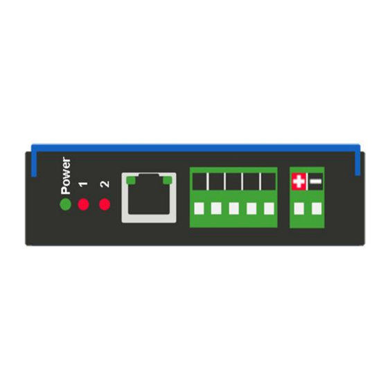
- Page 10 Hardware – NNA4 Powering the Gateway 1) Connect a 12-24 VDC power source to the gateway, Red Wire = (+) Black Wire = (-). a) The unit draws 175mA @ 12 V. Real Time Automation, Inc. 1-800-249-1612...
- Page 11 1) Mount your DIN Rail. 2) Hook the bottom mounting flange under the DIN Rail. 3) While pressing the 460PSAZR-NNA4 against the rail, press up to engage the spring loaded lower clip and rotate the unit parallel to the DIN Rail.
- Page 12 Accessing the Main Page The following steps will help you access the browser based configuration of the gateway. By default, DHCP is enabled. If the gateway fails to obtain an IP address over DHCP it will Auto IP with 169.254.X.Y. For more information on your Operating system network setting refer to the Accessing Browser Configuration...
- Page 13 Error: Main Page Does Not Launch If the Main Page does not launch, please verify the following: 1) Check that the PC is set for a valid IP Address a. Open a MS-DOS Command Prompt b. Type “ipconfig” and press enter c.
- Page 14 Committing Changes to the Settings All changes made to the settings of the gateway in Configuration Mode will not take effect until the gateway is restarted via the webpage. Changes will not be stored if the gateway’s power is removed prior to a reboot.
- Page 15 Main Page The main page is where important information about your gateway and its connections are displayed. Mode (orange box below): Running Mode: • Protocol communications are enabled • Configuration cannot be changed during Running Mode. If changes are needed, click the Configuration Mode button shown in the green box below...
- Page 16 Device Configuration The device configuration area is where you assign the device description parameter. Changes can only be made when the gateway is in Configuration Mode. Once you are done configuring the Description, click the Save Parameters button. Real Time Automation, Inc. 1-800-249-1612...
- Page 17 Network Configuration The network configuration area is where you assign the IP address and other network parameters. Changes can only be made when the gateway is in Configuration Mode. Once you are done configuring the Network Settings, click the Save Parameters button. If you are changing the IP Address of the gateway, the change will not take effect until the unit has been rebooted.
- Page 18 PROFINET IO Server Configuration Click the PROFINET IO Server button to display the configuration page. 1) Select which Network Interface to use for this PROFINET IO connection. If using single port hardware, the Network Interface will default to Ethernet Port only. 2) Device Name: This is the PROFINET name that is assigned by TIA Portal or Classic STEP 7.
- Page 19 Note: To properly set communication to the PROFINET controller, you will need to install the GSD file that is downloadable on the configuration web page or on the CD that was shipped with the unit. For instructions on how to do this, please see the Setting up the PLC- Example Using Simatic Step 7 software Setting up the PLC- Example Using TIA Portal sections.
- Page 20 PROFINET IO Server Slot Configuration The bottom area of the PROFINET IO Server Configuration page lets you configure multiple input and output slots. 1) Profinet server supports 1248 Input bytes and 1248 Output bytes. 2) Data Size is configurable. Options include: 8, 16, 32, 64, and 128 Bytes. 3) Data Format sets the formatting of the data.
- Page 21 PROFINET IO Server Slot Configuration: Auto-Configure While in either of the two Auto-Configure Modes, the data slots themselves cannot be edited. Auto- Configure Mode looks at the other protocol and then configures the data slots to match. The Data formats will be defined after the other protocol is configured. The data will be configured according to the following rules: 1) Any 8 Bit Signed/Unsigned data will be mapped as 8 Bit Int or 8 Bit Uint, matching signs whenever possible.
- Page 22 Auto-Configure Group by Device vs. Auto-Configure Group by Data Type There are two different methods for Auto-Configure: Group by Device or Group by Data Type. There are a couple of rules to keep in mind when using Auto-Configure Mode: 1) If the other protocol inside the gateway is a server, slave, or adapter protocol, then there are no differences between the Auto-Configure Modes.
- Page 23 PROFINET IO Server Slot Configuration: Manual Mode 1) To transition from either of the two Auto-Configure Modes to Manual Configure Mode, click the dropdown at the top of the PROFINET IO Server Configuration page and select Manual Configure. 2) When prompted, click OK to confirm mode change or Cancel to remain in Auto-Configure Mode. 3) Once OK is clicked, there are two options for how to proceed.
- Page 24 Setting up the PLC- Example Using Simatic Classic Step 7 This is how you would set up the following example in your controller. 1) In your project, click the CPU and you should see the hardware option in the right pane. Double click on the Hardware icon.
- Page 25 7) Click OK acknowledging that the install was successful. 8) If you navigate to the right-hand side, you will see the RTA profile under: PROFINET IO->Additional Field Devices->Gateway->460PSxx 9) IF YOU HAVE ALREADY CONFIGURED THE PROFINET I/O CONTROLLER, SKIP TO STEP 11.
- Page 26 11) Find the RTA device in the I/O tree. It will be under PROFINET IO->Additional Field Devices-> Gateway->460PSxx->460PSxx 1-port. 12) Once found, drag the Standard icon into the network line. Real Time Automation, Inc. 1-800-249-1612...
- Page 27 13) Double-click the gateway icon to open the properties window. If not already done, uncheck the Assign IP Address via IO controller option (some versions already do this) and press OK. Real Time Automation, Inc. 1-800-249-1612...
- Page 28 14) To Assign the RTA gateway a Device Name click on the RTA device, click on the PLC tab, select Ethernet, then Assign Device Name. 15) Click the Assign name button to give the RTA gateway a name. This name will appear on the RTA PROFINET configuration page.
- Page 29 16) Expand the Standard node on the right panel to show the available modules to insert (Refer to the picture in Step 11). To match the above configuration in the 460 gateway, add one 128-byte input module to slot 1, and one 128-byte output module to slot 11.
- Page 30 Setting up the PLC- Example Using TIA Portal This is how you would set up the following example in your controller. 1) In your project, click the Device View tab and select your PLC. 2) IF YOU HAVE ALREADY INSTALLED THE GSD FILE, SKIP TO STEP 9. OTHERWISE - Under Options, select Manage general station description file (GSD).
- Page 31 3) On the RTA PROFINET IO Server configuration page, download the zip file 4) Browse to folder containing the GSD file. 5) Check the box to the left of the imported path and click Install. 6) Click Close when it was installed successfully.
- Page 32 PLC to connect to. 10) Once the RTA device is in the network click the Device view tab. 11) From the dropdown menu select rta-460ps. Right click on the RTA device to select Properties. 12) Go down to the Ethernet addresses.
- Page 33 *The PROFINET Device Name field is the name to assign to the RTA gateway b. *Make sure the PROFINET device and the gateway are on the same network. 14) Right click on the RTA device and select the Assign device name.
- Page 34 15) Select the RTA device and click the Assign name button to give the RTA a valid name on the network. Once the RTA gateway is in run mode this name will appear on the PROFINET web page. 16) To match the above configuration in the 460 gateway, add one 8-byte input module to slot 1, one 128-byte input module to slot 2, and one 32-byte output module to slot 11.
- Page 35 17) Expand the Module list under the catalog on the right panel to show the available modules to insert into the device overview slots. To insert a module, double click to add it to the next available slot. Terminology Note and Example: I addresses refer to input, Q addresses refer to output, %B refers to bytes and %W refers to words.
- Page 36 Click the MQTT button to continue configuration. Microsoft Azure (AZR) Configuration You can only configure one Microsoft Azure connection with your RTA product. 1) To add an ARZ connection, click the -Select- dropdown menu under MQTT Client Connection List and select Add Generic AZR Connection option.
- Page 37 7) Keep Alive: Enter in the amount of time that the gateway should attempt to ping the broker to keep the MQTT connection alive, 0 disables this feature. 8) Client ID: The MQTT client ID to be used when connecting to the Broker. a.
- Page 38 a) NOTE: Subscribe paths on Microsoft Azure are limited to 1 and are not user configurable. This is due to Microsoft Azure not utilizing a typical pub/sub broker and is instead using Cloud-to- Device messaging and expecting a pre-defined endpoint for these messages. The subscribe path may not populate immediately when generated, to resolve this, click view subscribe paths and then hit save parameters with the subscribe paths selected.
- Page 39 Microsoft Azure Service Setup Please note this section outlines the bare minimum configuration to get the RTA gateway connected to Azure and is not necessarily a recommended configuration in a production environment. 1. Create a Microsoft Azure subscription if you do not have one already 2.
- Page 40 d. Hit Review + Create in the bottom left corner. e. In the review window, hit create in the bottom left corner to create the resource group. You should be re-directed back to the resource groups window where you can see the newly created resource group is listed.
- Page 41 b. Select the resource group created previously, enter a name for the hub, and select a region. c. Hit Next at the bottom of the page to proceed to the networking tab. d. In the networking tab under connectivity configuration, ensure public access is selected. e.
- Page 42 g. One the deployment is completed click on “Go to Resource” to be re-directed to the newly created IoT Hubs overview page. If go to resource is not an option, navigate to the IoT hub and select your newly created IoT hub to access the overview page. h.
- Page 43 Copy the Primary connection string for the device, this will be used when connecting the RTA gateway to Azure. Real Time Automation, Inc. 1-800-249-1612...
- Page 44 4. Create an Event Hub a. In the search bar at the top type in “Event Hubs” and select the Event Hubs under services to navigate to the Event Hubs page. b. Hit Add in the top left corner, there may also be a create Event Hub button in the middle if no Event Hubs Namespaces exist.
- Page 45 Once the namespace has finished initializing click on go to resource to navigate to the namespaces main panel. If go to resource in not an option navigate to Event Hubs and select the newly created namespace to open the main panel. g.
- Page 46 You should be returned to the namespace overview, scroll down and you should see the newly created event hub at the bottom of the overview section. 5. Create an Event Grid System Topic a. In the search bar at the top type in “Event Grid System Topics” and select the event grid system topics option under services to navigate to the even grid system topics page..
- Page 47 d. Click Review + create in the bottom left corner. e. On the review + create page click create the create the Event Grid System Topic. Once the event grid system topic is initialized click go to resource to navigate to the Event Grid System Topic Panel.
- Page 48 ii. Under event types, ensure that Device Created, Device Deleted, Device Connect, Device Disconnect, and Device Telemetry are all selected. iii. Under Endpoint Select Event Hub as the endpoint type. iv. Under endpoint details click “Configure an Endpoint” v. In the newly opened Select Event Hub window, select your azure subscription, resource group, namespace, and event hub and click confirm selection.
- Page 49 Testing Microsoft Azure Communication Once you have the Azure configured, you can use their Azure IoT Explorer utility to test the connection is working. To set up Azure IoT Explorer: 1. open the utility and select the IoT Hubs tab on the left 2.
- Page 50 Selecting a device within the hub will provide device specific information such as its Primary Connection string. It also provides useful tools for seeing data being from the device to Azure as well as send test messages from Azure to the device. Real Time Automation, Inc.
- Page 51 Cloud-to-device message tab on the left. In the Cloud-to-device message tab, enter the message to be sent to the RTA in the message body section and click Send message to device at the top of the page. An example payload for the configuration above can be seen in the image below.
- Page 52 Navigate to the RTA display data page, view data from MQTT, refresh the page, and the value should be visible as shown below. Real Time Automation, Inc. 1-800-249-1612...
- Page 53 Send data from RTA gateway to Microsoft Azure (Publish Topics) This example shows a PLC writing data to the RTA gateway and presenting that data to the Publish topic on Microsoft Azure Real Time Automation, Inc. 1-800-249-1612...
- Page 54 In Azure IoT Explorer, navigate to the device you would like to publish data to and select the telemetry tab on the left. In the telemetry window click Start in the top left corner. Any messages published to the selected device will now be shown in the telemetry window. Real Time Automation, Inc.
- Page 55 QT Publish Trigger By default, the RTA gateway will publish to the broker based on change of state. This means a new publish to the broker will occur any time a value changes. In an application where the client is being charged per publish, such as with Azure, this is not ideal.
- Page 56 Mapping - Transferring Data Between Devices There are 5 ways to move data from one protocol to the other. You can combine any of the following options to customize your gateway as needed. Option 1 – Data Auto-Configure Mappings: The gateway will automatically take the data type (excluding strings) from one protocol and look for the same data type defined in the other protocol.
- Page 57 Display Mapping and Values The Display Data and Display String pages are where you can view the actual data for each mapping that is set up. Display Data Click the Display Data button to view how the data is mapped and what the values of each mapping are. Here you will see how each data point (excluding strings) is mapped.
- Page 58 This page is very useful when verifying that all data is mapped somehow from one protocol to another. If a data point is not mapped, it will display on this page in a yellow highlighted box. The Display Data page will display up to 200 mappings per page, simply navigate to the next page for the additional mapping to display.
- Page 59 To view the actual data mappings, click the Edit Mapping button. For more details, see the Data Mapping-Explanation section. To view the data mappings purely as text, click the View as Text button. For more details, see the View Data Mapping as Text section. Real Time Automation, Inc.
- Page 60 Display String Click the Display String button to view what the values of each Parsing and/or Concatenating strings are, you can also click on the Edit Mapping to view the mapping of each string. To view the source or destination groups from a string, click the dropdown menu to generate the information regarding that device.
- Page 61 If there are values of “Data Not Valid “on this page, it indicates that the source has not been validated yet and no data is being sent to the destination. NOTE: You can view the whole string data by clicking on Diagnostics Info drop down and navigating to ASCII Diagnostics page.
- Page 62 Display String use case Sending a message of “RTA,Support,Rocks” from an ASCII device to the RTA unit. The ASCII Parsing Configuration would look like my example below. There are more detailed examples of what all the fields represent in the ASCII Parsing section.
- Page 63 Data and String Mapping – Auto-Configure The Auto-Configure function looks at both protocols and will map the data between the two protocols as best as it can so that all data is mapped. Inputs of like data types will map to outputs of the other protocols like data types first.
- Page 64 Data Mapping – Explanation Below are the different parts that can be modified to make up a data mapping. 1) Enable (red box above): Check to enable mapping. If not checked, this mapping is skipped. 2) Source Field (yellow box above): a) Group - Select the data group you set up in the protocol config to use for this mapping.
- Page 65 The gateway operates at 200 ticks per second. This equates to one tick every 5ms. Thus, mapping this to a destination will give easy confirmation of data flow without involving one of the two protocols. If data stops on the destination end, then the RTA is offline. Real Time Automation, Inc.
- Page 66 4) Heartbeat 100ms Update a) The Heartbeat 100ms Update variable can be used as a heartbeat that updates once every 100ms. The variable starts at 0 on gateway startup and increments by 1 every 100ms. This can be mapped into a destination on one of the available protocols to monitor the gateways connection status.
- Page 67 c) There are multiple ways to map the NetBmpStat. Option 1: Map the whole 32bit value to a destination. Example below shows the NetBmpStat is going to an Analog BACnet object. Using a connection of 5 Modbus Slave devices AI1 will show a value of 31.0000. Open a calculator with programmer mode and type in 31, this will represent bits 0 –...
- Page 68 7) Status_XY a) There are two Statuses provided, one for each protocol. This gives access to the overall status of that Protocol. Each Bit has its own meaning as follows: Common Status: 0x000000FF (bit 0-7)1 byte Hex: Bit Position: Decimal: Explanation: 0x00 if we are a Slave/Server...
- Page 69 Non-Recoverable Faults 0xFF000000 (bit 24-31)4 byte Hex: Bit Position: Decimal: Explanation: 0x01 16,777,216 nonrecoverable fault – task fatal err 0x02 33,554,432 nonrecoverable fault – config missing 0x04 67,108,864 nonrecoverable fault – bad hardware port 0x08 134,217,728 nonrecoverable fault – config err 0x10 268,435,456 Configuration Mode...
- Page 70 String Mapping – Explanation Below are the different parts that can be modified to make up a string mapping. String data types can only be mapped to other string data types. There is no manipulation that can be done on the string. 1) Enable (red box above): Check to enable mapping.
- Page 71 Mapping – Auto-Configure Mode to Manual Configure Mode To transition from Auto-Configure Mapping Mode to Manual Configure Mode, click the dropdown at the top of the Mapping Configuration page and select Manual Configure. After you click this button, you will be prompted to confirm if this is really what you want to do. Click OK to proceed to Manual Configure Mode or click Cancel to remain in Auto-Configure Mappings Mode.
- Page 72 Mapping – Manual Configure Mode to Auto-Configure Mode To transition from Manual Configure Mode to Auto-Configure Mapping Mode, click the dropdown menu at the top of the Mapping Configuration page and select Auto-Configure Mappings. Click OK to proceed to delete all current mappings and go back to Auto-Configure Mappings Mode. Click Cancel to keep all mappings and remain in Manual Configure Mode.
- Page 73 View as Text Data Mapping The View as Text page displays the point to point mapping(s) you set up in the Data Mapping section. This will also display any manipulation(s) that are configured. Each line on this page will read as follows: ->...
- Page 74 Note: # is an internal reference to the Server/Slave number you are settings up. ex. RTA Server/Slave products can only be Trigger 1 and Handshake 1 since we are only 1 device. If RTA is a Master/Client, then you can have a Trigger# for each server/slave connected too.
- Page 75 3) Within the Data Mapping page manually add 2 additional mappings. 4) The first mapping is going to be the Data Validation Triggering. AO21 will write to the RTA, MC Trigger 1 will mark data invalid. 5) The second mapping, the MC Handshake will increment that all data is validated and write to AI21 “all data is validated”.
- Page 76 Security Configuration To setup security on the 460 gateway, navigate to Other->Security Configuration. You can configure Security for 3 administrators, 5 users, and 1 guest. THIS IS A TOTAL SECURITY FEATURE The security feature offers a way to password protect access to diagnostics and configuration on the network.
- Page 77 Security Configuration-Security Levels Each webpage in the gateway can have a separate security level associated with it for each user. Security Levels: 1) Full Access: Capability to view and configure a web page. 2) View Access: Capability to view a web page, but cannot configure parameters. 3) No Access: No capability of viewing the web page and page will be removed from Navigation.
- Page 78 Security - Log In Username: Name of the user to login. Password: Password of the user to login. Log In: If login is successful, the user will be redirected to the Main Page. Send Password to Email: Sends the specified User’s Password to the email configured for that user. Display Hint: Displays the hint specified for the User if one was set up.
- Page 79 Email Configuration To setup e-mails on the 460 gateway, navigate to Other->Email Configuration. You can configure up to 10 email addresses. 1) SMTP Mail Username: The email address that the SMTP server has set up to use. 2) SMTP Mail Password: If authentication is required, enter the SMTP Server’s password (Optional). 3) SMTP Server: Enter the Name of the SMTP Server or the IP Address of the Server.
- Page 80 Alarm Configuration To setup alarms on the 460 gateway, navigate to Other->Alarm Configuration. 1) Alarm Delay upon Powerup: At Powerup, the gateway will have values of ‘0’ stored for all data. This may cause alarms to trigger before these values are updated by the mating protocols. Set this field to provide needed time to update fields before considering values for alarms.
- Page 81 5) In the Clear Error Section: a. Select the Clear Error Operation. Available options are <, >, <=, >=, !=, ==, and Change of State (COS). This is the operation that will be used to compare the Data Point value against the Error Value to determine if the alarm needs to be cleared.
- Page 82 Diagnostics – Alarm Status Alarm Status will only display under the Diagnostic menu tab if at least 1 Alarm is enabled. 1) # Alarms Enabled: This is a count of enabled alarms. 2) # Alarms Active: This is how many alarms are presently active (set). 3) Last Active Alarm: This is the last alarm that the gateway detected.
- Page 83 Alarms – Clear When an alarm is cleared, the following will occur: 1) A one-time notification will be sent to the email associated with the alarm. a. For duplicate emails to occur, the alarm must become active and then be cleared again. 2) Total # Alarms Active will decrement.
- Page 84 Change of State (COS) Configuration To access the configuration files in the 460 gateway, navigate to dropdown Other->COS Configuration. The gateway, by default only writes when data has changed. The gateway also waits to write any data to the destination until the source protocol is successfully connected. Default values should fit most applications.
- Page 85 Diagnostics Info The Diagnostics page is where you can view both protocols’ diagnostics information, # of Data Mappings, # of String Mapping and # Alarm Mappings. For protocol specific diagnostic information, refer to the next few pages. Diagnostics Mapping This section displays the number of mappings that are enabled, Data Mapping and String Mapping will show the # of Errors and First Errors.
- Page 86 Diagnostics – PROFINET IO Server Select the PROFINET IO Server in the dropdown menu on the Diagnostics Page to view a breakdown of the diagnostics and common strings that are displayed on the page. Additional diagnostic information can be found by clicking the Help button. NOTE: This page will auto-refresh every five seconds with the latest data.
- Page 87 Variables: 1) Application Ready Rcvd: a) The Application Ready Command has been received b) The gateway has completed the PROFINET setup sequence and will start cyclic communication 2) Release AR: a) A Release Application Relationship command has been received b) PROFINET communication have been disconnected from the gateway 3) Parameters Written: a) Rollover counter for the number of parameters written by the IO controller.
- Page 88 Diagnostic – MQTT Client Select the MQTT Client in the dropdown menu on the Diagnostic page to view the breakdown of the diagnostics and common strings that are display on the page. You may also view the individual MQTT device counters by selecting the device in the All Devices drop down and clicking View. NOTE: This page will auto-refresh every five seconds.
- Page 89 LED Status Solid Green (Connected): • The gateway is connected to all the MQTT devices that are configured and enabled Flashing Green (Not Connected): • No MQTT devices are configured / enabled. Go to the MQTT Client Device Configuration to configure a device Flashing Red (Not Connected): •...
- Page 90 LED Configuration To modify the behavior of the LEDs on the 460 gateway, navigate to Other->Setup LEDs. Each LED may be set to Disabled, Protocol 1, or Protocol 2. If either protocol is a master/client, you may set the LED to represent either all slaves/servers configured in the gateway or a slave/server device. To select a slave/server device: 1) Select the protocol in the left dropdown menu.
- Page 91 Configuration Files To access the configuration file in the 460 gateway, select the dropdown Other->Export/Import Config. Export Configuration The Export Configuration allows you to save your configuration file for backup or to be imported into another gateway. This file is named rta_cfg.rtax by default. Upon clicking the Save Configuration to File button, you will be prompted to select a location to save the file.
- Page 92 If it encountered an error while trying to load the saved configuration, the gateway will indicate the first error it found and a brief description about it under the Load Configuration button. Contact RTA Support with a screenshot of this error to further troubleshoot.
- Page 93 Save and Replace Configuration Using SD Card Saving Configuration Using SD Card This function saves the gateway’s configuration automatically to an SD Card each time the gateway is rebooted via the Restart Now button on the web page. If this unit should fail in the future, the last configuration stored on the SD card and can be used for a new gateway to get the application back up and running quickly.
- Page 94 Intelligent Reset Button If the IP Address of the gateway is forgotten or is unknown, there is an easy way to recover the IP Address using a reset button on the hardware. 1) On the side of the gateway with the SD card slot, there is a small pinhole. Using a paperclip, press the button through this pinhole and hold the button for at least 5 seconds.
- Page 95 Utilities To access the Utilities page in the 460 gateway, navigate to Other->Utilities. The Utilities screen displays information about the gateway including Operation Time, File System Usage, Memory Usage, and Memory Block Usage. Here you can also: • View the full revision of the software. •...
Need help?
Do you have a question about the 460PSAZR-NNA4 and is the answer not in the manual?
Questions and answers